High availability scenarios
This section describes architecture scenarios for the Core High Availability (HA) solution. Each scenario focuses on key components. These scenarios are typical, but not inclusive, and illustrate examples of different network and data center configurations. There could be different redundant combination of Core servers across multiple data centers with many different routing network connections. The diagrams outline the important components and port connectivity required to ensure proper operation.
Two Core servers across two data centers
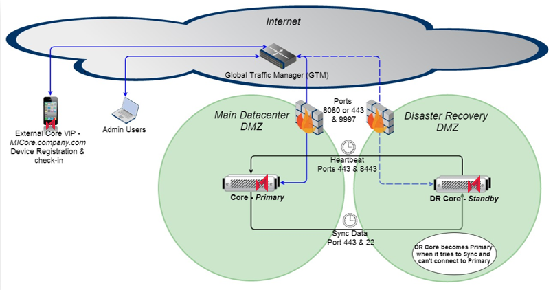
This example shows the simplest Core High Availability (HA) Architecture with its related components.
Disable SSH protection on the Firewall when connecting between two Cores
Figure 1. Two Core servers across two data centers

The components in the diagram are:
-
One data center hosts the Primary Core.
-
A second, Disaster Recovery (DR), data center hosts the Secondary Core.
-
A Global Traffic Manager (GTM) or DNS or load balancer controls traffic to the Primary. This “traffic controller” monitors the health of the Primary and Secondary servers. When it detects the Primary has become unresponsive, it routes traffic to the Secondary.
-
The Secondary Core checks the status of the Primary through a process called “heartbeat”. This process is configured during HA Standby setup. This process detects if the Primary becomes unresponsive. When this happens it initiates the failover process. When a failover occurs, the Secondary attempts to become Primary, depending on what settings have been configured; it might stay as a Secondary or become Primary.
-
The Secondary periodically synchronizes with the Primary ensuring it has the latest changes as the Primary. The synchronization process frequency is configurable and is automated.
-
The ports used to communicate between Cores are ports 8443, 443 and 22 as outlined in the diagram. This intra-Core communication is essential for proper Core HA operation.
Three Core servers across two data centers
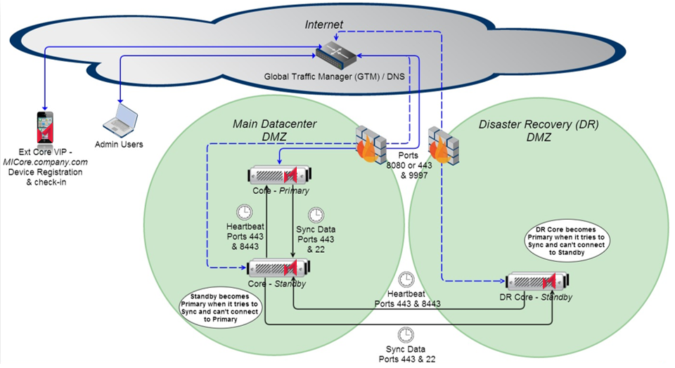
The example in this section shows high availability in the Main data center using a disaster recovery approach.
Figure 2. Two Core servers across two data centers

This approach is typically used in environments where a main data center is expected to be always available and a Disaster Recovery data center is exclusively used as part of business continuity approach and typically requires manual intervention to bring online.
The key components in this architecture include:
-
A main data center hosting a pair of Cores. This pair of Cores is set up as Primary and Secondary. These two Cores served as the main Core High Availability solution. The third Core serves as part of the Disaster Recovery (DR) configuration and it resides in the DR data center.
-
Another data center (Disaster recovery) hosting a third Core in Secondary mode.
-
A Global Traffic Manager (GTM) or DNS or load balancer that controls the traffic to the Primary Core. This “traffic controller” monitors the health of the other Cores and detects when the Primary becomes unresponsive and begins routing traffic to the Secondary in the Main data center or DR data center in case of Main data center failure. This is how external traffic is controlled and routed to the Primary Cores.
-
The Secondary Core checks the status of the Primary through a process called “heartbeat”. This process is configured during HA Standby setup. This process detects if the Primary becomes unresponsive. When this happens it initiates the failover process. When a failover occurs, the Secondary attempts to become Primary, depending on what settings have been configured; it might stay as a Secondary or become Primary. In the case of the Core located in the DR data center, it sees the Secondary in the Main data center as its Primary Core and the failover process takes place between these two Cores.
-
The Secondary Cores periodically synchronizes with its paired Primary Core, ensuring it has the latest changes as the Primary. The synchronization process frequency is configurable and is automated.
-
The ports used to communicate between Cores are ports 8443, 443 and 22 as outlined in the diagram. This intra-Core communication is essential for proper Core HA operation.
Two Core servers and two Sentry servers on one data center
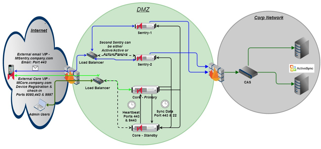
The example in this section describes a typical Core and Sentry High Availability Solution.
Figure 3. Two Core servers and two Sentry servers on one data center

While the Sentry HA details are outside the scope of this document, it is used here to show a typical Core complete HA solution architecture. For details about Sentry, please refer to the latest Standalone Sentry Installation Guide.
The key components in this architecture include:
-
One data center hosting a pair of Cores. This pair of Cores is set up as Primary and Secondary. These two Cores serve as the Core High Availability solution. The Sentry setup serves the same purpose, but unlike the Cores, they can be configured in Active/Active or Active/Standby configuration.
-
A DNS or load balancer that controls the traffic to the Primary Core and Sentry. This “traffic controller” monitors the health of the other Core and detects when the Primary becomes unresponsive and begins routing traffic to the Secondary Core. This is how external traffic is controlled and routed to the Primary Core.
-
The Secondary Core checks the status of the Primary through a process called “heartbeat”. This process is configured during HA Standby setup. This process detects if the Primary becomes unresponsive. When this happens it initiates the failover process. When a failover occurs, the Secondary attempts to become Primary, depending on what settings have been configured; it might stay as a Secondary or become Primary.
-
The Secondary Cores periodically synchronizes with its Primary Core ensuring it has the latest changes as the Primary. The synchronization process frequency is configurable and it is automated.
-
The ports used to communicate between Cores are ports 8443, 443 and 22 as outlined in the diagram. This intra-Core communication is essential for proper Core HA operation.
Three Core servers and two Sentry servers on two data centers
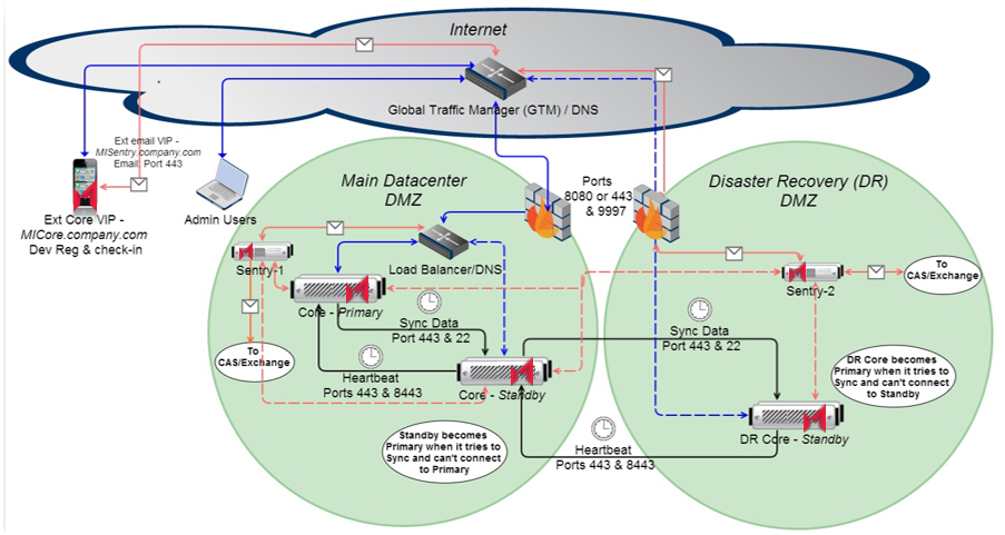
The example in this section describes one of the most complete and complex Core/Sentry HA Architectures with all related components.
Figure 4. Three Core servers and two Sentry servers on two data centers

The key components in this architecture include:
-
A main data center hosting a pair of Cores. This pair of Cores is set up as Primary and Secondary. These two Cores serve as the main Core High Availability solution.
-
Another data center for Disaster Recovery (DR), hosting a third Core in Secondary mode. The third Core serves as part of the DR configuration and it resides in the DR data center. This data center also hosts a Sentry to provide High Availability to the Primary Sentry.
-
A Global Traffic Manager (GTM) or DNS that controls the external traffic to the Main data center or the DR data center. This “traffic controller” monitors the health of the Primary Cores and detects when the Primary becomes unresponsive and begins routing traffic to the Secondary in the Main data center or DR data center in case of a Main data center failure. Within the data center, there is a load balancer, which takes care of monitoring the state of the Cores and routing the traffic accordingly. The same concept applies to the Sentry and a second Sentry can be installed in the Main data center to allow for redundancy within the same data center.
-
The Secondary Core checks the status of the Primary through a process called “heartbeat”. This process is configured during HA Standby setup. This process detects if the Primary becomes unresponsive. When this happens it initiates the failover process. When a failover occurs, the Secondary attempts to become Primary, depending on what settings have been configured; it might stay as a Secondary or become Primary. In the case of the Core located in the DR data center, it sees the Secondary in the Main data center as its Primary Core and the failover process takes place between these two Cores.
-
The Secondary Cores periodically synchronizes with its “Primary Core” ensuring it has the latest changes as the Primary. The synchronization process frequency is configurable and is automated.
-
The ports used to communicate between Cores are ports 8443, 443 and 22 as outlined in the diagram. This intra-Core communication is essential for proper Core HA operation.