Deploying an Active/Passive Cluster
This example describes the tasks involved in deploying an active/passive cluster.
Overview
Active/passive clustering is supported only if the members of the cluster pair are in the same subnet because the VIP address must be shared by both the members. An active/passive cluster configuration provides high availability. Active/passive configurations allows seamless failover without the need to set up any external equipment, which is achieved by state synchronization between the two devices for all the configurations so that the devices are virtually identical. The Ivanti access control service uses a virtual IP (VIP) address to address the cluster pair in addition to addressing each device. The IP address takeover (IPAT) approach is used for the VIP address. If the active node fails, the passive node takes over the VIP address and sends a gratuitous Address Resolution Protocol (ARP) message notifying other networking devices that it now owns the VIP address. You should check that other devices in your network, especially the next-hop gateways, will honor the gratuitous ARP messages.
Topology
The following figure shows active/passive clustering.
This feature does not provide increased throughput or capacity but does create redundancy in the case of a failure.
Requirements
We recommend that you deploy a cluster in a staging environment first and then move to a production environment after testing the authentication realm, user role, and resource policy configurations, as well as any applications your end users might access.
You must follow these considerations when deploying a cluster:
•Cluster members must run the same software version.
•Cluster members must use the same hardware platform.
•State synchronization must occur only through the internal Network Interface Card (NIC).
•Ensure the cluster communication and resource access must take place over an internal network.
When choosing and configuring a load balancer for your cluster, we recommend that you ensure the load balancer:
•Supports IPsec
•Listens for traffic on multiple ports
•Can be configured to manage traffic using assigned source and destination IP addresses (not destination port)
Guidelines and Limitations
•A virtual IP address (VIP) address is shared by all the devices in the cluster. In an active/passive configuration, you configure the VIP address.
•You can deploy active/passive clustering only within the same IP subnet.
Configuring an Active/Passive Cluster
You use the primary node admin GUI to create the cluster and add members. The primary node is added as part of the cluster creation operation. When you add members, you are prompted for settings unique to the member, such as the name and IP address configuration for the internal and external interfaces. A few additional settings are also unique, namely the management port and VLAN port settings, so you add these manually after the add node procedure that follows, but before the join cluster operation.
If IPv6 is required, then configure both the nodes with IPv6 settings before creating the cluster.
To create a cluster and add members:
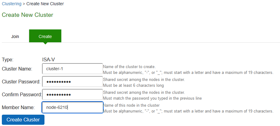
1.Select System > Clustering > Create Cluster and enter a name for the cluster, a cluster password, and a name for this node, such as Node-X.
You need to enter the password again when specifying additional nodes to join the cluster. All nodes in the cluster use this password to communicate.
The following figure shows the Create New Cluster page.
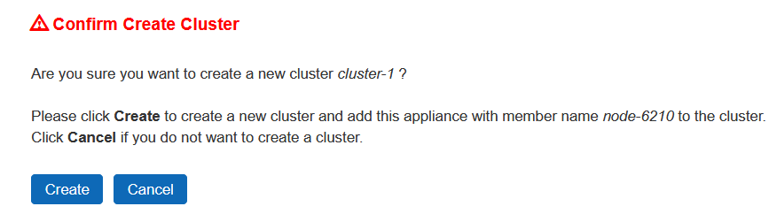
2.Click Create Cluster. When prompted to confirm the cluster creation, click Create. After the device initializes the cluster, the Clustering page displays the Status and Properties tabs.
3.Click Properties and select Active/Passive configuration.
The following figure shows the Clustering page for Connect Secure.
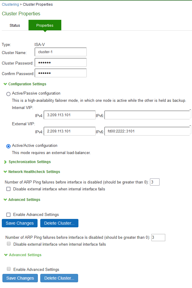
4.Complete the configuration as described in the following table.
Settings | Guidelines |
Specifies a name to identify the cluster. | |
Configuration Settings | |
Active/Passive configuration | Select this option to run a cluster pair in active/passive mode. Then, specify an internal VIP (virtual IP address) and an external VIP if the external port is enabled. |
Active/Active configuration | Select this option to run a cluster pair in active/active mode. Active/Active runs a cluster of two or more nodes in active/active mode using an external load balancer. To change a two-unit active/passive cluster to an active/active cluster with more than two nodes, first change the configuration of the two-unit cluster to active/active and then add the additional nodes. |
Synchronization Settings | |
Synchronize log messages | Select this option to propagate all log messages among the devices in the cluster. |
User/Session Synchronization | |
Configuration only cluster | Select this option to disable synchronization of session data and to replicate only configuration data and user records (for example, web bookmarks, NFS and windows shared files, terminal servers, telnet sessions, SAM, preferences, and passwords). Enabling this option limits data transfers between the cluster nodes. User and Session specific limits are only enforced on the node and not across the cluster. |
Synchronize user sessions | Select this option to synchronize all user session information (for example, instances of access to intranet services) among all the devices in the cluster. |
Synchronize last access time for user sessions | Select this option to propagate the latest user access information across the cluster. |
If you configure your cluster as active/passive, the Synchronize user sessions and Synchronize last access time for user sessions options are automatically selected. If you select both Synchronize log messages and Synchronize user sessions check boxes, everything is replicated on the cluster nodes, including networking information. Even though networking information, including syslog and SNMP settings, can be configured per node or per cluster, all of the networking information is synchronized between nodes when these two options are set. If your cluster node configurations diverge because of changes made to one node while another is disabled or unavailable, the system manages the remerging of the configurations automatically, for up to 16 updates. Beyond the maximum number of allowable updates, you might need to intervene and remerge the configurations manually. In some instances, the system might be unable to remerge the configurations if there is not enough overlapping configuration information between two nodes to manage the internode communication. For example, for a two-node cluster in which the two nodes are partitioned from each other because of a network outage, if the internal network IP address of one of the nodes changes in one of the partitions, the two partitions are unable to rejoin, even when the network is repaired. In such a case, you must remerge the configurations manually. | |
Network Healthcheck Settings | |
Number of ARP Ping Failures | Specify the number of ARP ping failures allowed before the internal interface is disabled. |
Disable external interface when internal interface fails | Select this option to disable the external interface of the device if the internal interface fails. |
Advanced Settings | |
Enable Advanced Settings | Select the Advanced Settings check box to specify the timeouts for the underlying cluster system. Do not change any values under this setting unless instructed to do so by Ivanti Technical Support. |
Network Type | Select the appropriate network type. Network type selection controls the timeouts used by the underlying cluster system. Change this value only when you observe repeated cluster partitions that may be related to long network delays or significant load in any of the cluster nodes. A non-default network type cannot be used in conjunction with non-default timeout multipliers. If a non-default network type is picked, the timeout multiplier will silently get reset to the default value. |
Timeout Multiplier | Default cluster timeouts have been picked to be optimal for typical cluster installations. Administrators have the ability to adjust the cluster timeouts over a linear scale of 1-20. Smaller timeouts result in faster failure detection. Larger timeouts minimize the risk of cluster splits during transient network glitches. The system can be instructed to pick a reasonable default for the current cluster configuration by specifying a value of 0. A non-default timeout multiplier can only be used in conjunction with the default network type. If a non-default network type is picked, the timeout multiplier will silently get reset to the default value. |
5.Click Save Changes. After Connect Secure initializes the active/passive cluster, the Clustering page displays the Status and Properties tabs.
6.Click Add Members to specify additional cluster nodes.
The following figure shows the page for Connect Secure.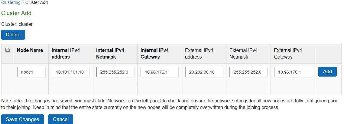
7.Click Save Changes.
8.Select System > Network > Management Port > Settings and configure the management port IPv4 and IPv6 (if configured) of node-2. The following figure depicts Configuring Management Port
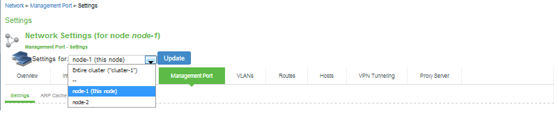 s
s
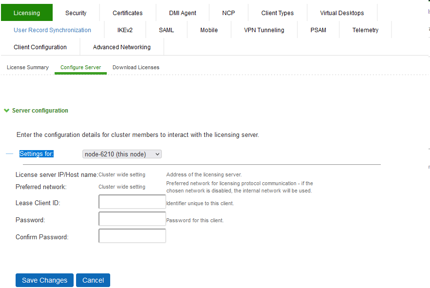
9.If a license server needs to be configured on both the nodes of a cluster, then perform the following steps:
•Navigate to Configuration >Licensing > Configure Server.
•Select the setting for Entire cluster.
•Configure the License server IP and preferred network.
•Click Save Changes.Configuring License Server for Entire Cluster
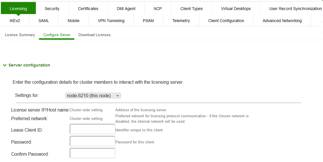
•Now, select the settings for node-wise and provide Lease Client ID, Password and Çonfirm Password for each node.
The following figure depicts Node-wise Server Configuration
Joining Nodes to the Cluster
The primary node joins the cluster as part of the creation process.
To join additional nodes to the cluster:
1.From an existing cluster member, select the System > Clustering > Cluster Status tab and specify the node you want to add to the cluster.
2.From the admin console of the node you want to add to a cluster:
•Select the System > Clustering > Join tab and enter:
•The name of the cluster to join
•The cluster password you specified when defining the cluster
•The IP address of an active cluster member
•Click Join Cluster. When prompted to confirm joining the cluster, click Join.
While the new node synchronizes its state with the existing cluster member, each node's status indicates Enabled, Enabled, Transitioning, or Enabled, Unreachable.
When the node finishes joining the cluster, its Clustering page shows the Status and Properties tabs. After the node joins the cluster, you might need to sign in again.
Verifying
|
Purpose |
Verifying the configuration on System > Clustering > Cluster Status page. |
|
Action |
Select System > Clustering > Cluster Status. |
The following figure hows the status on the Clustering page for Connect Secure.
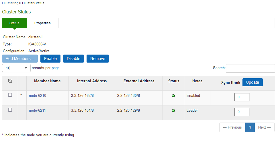
Table describes the information displayed on the Status tab and the various management tasks you can perform, including disabling, enabling, and removing a node from a cluster.
|
GUI Element |
Description |
|
Displays the cluster name, type, configuration, internal VIP, and external VIP for an active/passive cluster. |
|
|
Add Members button |
Click this button to specify a node you intend to add to the cluster. You can add multiple nodes at the same time. |
|
Enable button |
Click this button to add a node that was previously disabled. When you add a node, all state information is synchronized on the node. |
|
Disable button |
Click this button to disable a node within the cluster. The node retains awareness of the cluster but does not participate in state synchronizations or receive user requests unless members sign in to the node, directly. |
|
Remove button |
Click this button to remove the selected node or nodes from the cluster. After removal, the node runs in standalone mode. |
|
Fail-Over VIP |
Click this button to failover the VIP to the other node in the active/passive cluster. Only available if cluster is configured as active/passive. |
|
Member Name column |
Lists all nodes belonging to the cluster. You can click on a node's name to modify its name and network settings. |
|
Internal Address column |
Shows the internal IP address of the cluster member using Classless Interdomain Routing (CIDR) notation. |
|
External Address column |
Shows the external IP address of the cluster member using CIDR notation. Note that this column shows only the external IP address of the cluster leader unless you specify a different address for the node on its individual network settings page, which is accessible by clicking its name in the Member Name column. If you change the external IP address on the Network > Network Settings page, the change affects all cluster nodes. |
|
Status column |
Shows the current state of the node: •Green light, Leader - The node is the active member of an active/active cluster and is handling user requests. •Green light/enabled - The node is handling user requests and participating in cluster synchronization. •Yellow light/transitioning - The node is joining the cluster. •Red light/disabled - The node is not handling user requests or participating in cluster synchronization. •Red light/enabled, unreachable - The node is enabled but because of a network issue, it cannot be reached. A node's state is considered standalone when it is deployed outside of a cluster or after being removed from a cluster. |
|
Notes column |
Shows the status of the node's connection to the cluster: •OK - The node is actively participating in the cluster. •Transitioning - The node is switching from the standalone state to the enabled state. •Unreachable - The node is not aware of the cluster. A cluster member might be unreachable even when it's online and can be pinged. Possible reasons include: its password is incorrect, it doesn't have information about all cluster nodes, it's configured with a different group communication mode, it is running a different service package version, or the machine is turned off. |
|
Sync Rank column |
Specifies the synchronization order for nodes when a node rejoins a cluster. Accepts sync ranks from 0 (lowest rank) to 255 (highest rank). The highest rank takes precedence. If two nodes have identical sync ranks, the alphanumeric rank of the member name is used to determine precedence. |
|
Update button |
Updates the sync rank after you change the precedence of the nodes in the Sync Rank column |