Deploying ICS Active-Active Cluster using Virtual Traffic Manager in Microsoft Azure
This section describes deploying ICS A-A cluster with vTM load balancer in Microsoft Azure.
Deploying ICS A-A Cluster Topology Diagram
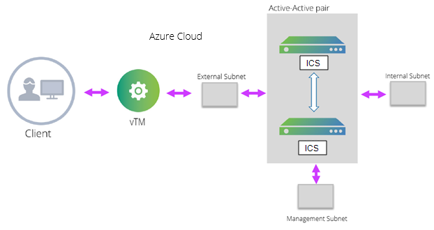
The deployment process involves the following steps:
•Deploying Two ICS EC2 instances Using ARM Template
•Forming the Active-Active Cluster
Deploying Two ICS EC2 instances Using ARM Template
ICS can be deployed in Azure using ARM template in a 3-armed model. Based on the need, deploy two ICS instances using the json template from one of the following zip files:
•ics-3-nics.zip
•ics-3-nics-existing-vnet.zip
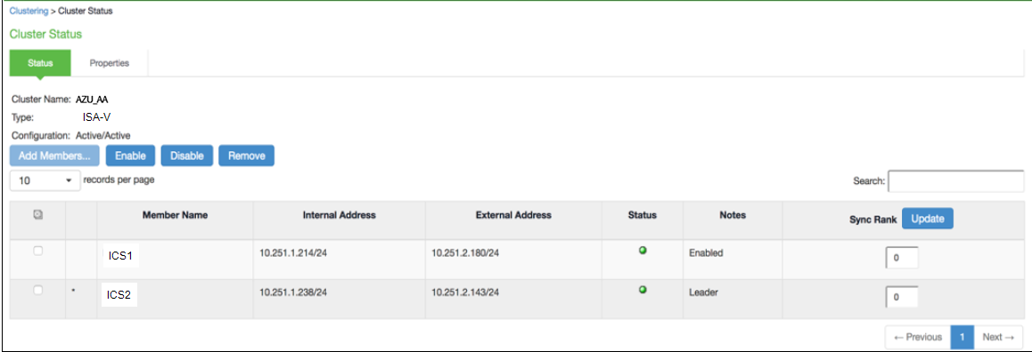
Forming the Active-Active Cluster
Once the two ICS instances are initialized, form the Active-Active cluster between them. For details about creating ICS clusters, refer to ICS Administration Guide.
ICS A-A Cluster Status
Clustering Support with Cloud
Only A/A clustering is supported.
Adding Load Balancing and Inbound Network Security Rules
To manage an additional service in your Traffic Manager cluster, or if the existing service uses multiple ports or protocols, add load balancer and network security rules after creating the cluster.
Ivanti recommends using standalone nodes or clusters of a maximum of 2 nodes behind a load balancer.
Ivanti Security Appliance (ISA) does not support clusters containing more than two nodes for ICS.
To add load balancing rule, perform the following steps:
1.Navigate to your resource group.
2.Click the Load Balancer resource name (typically named “<clustername>-vtmLB”).
3.From the load balancer settings pane, click Load balancing rules.
4.Click Add.
Add Load Balancing Rule
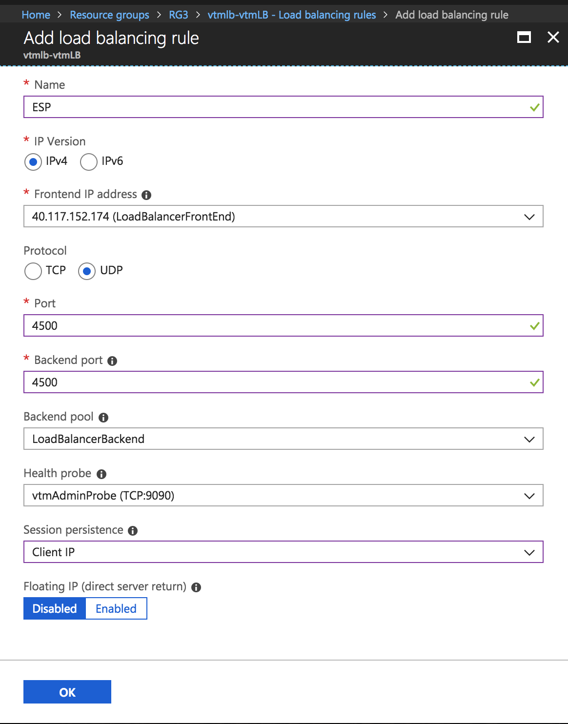
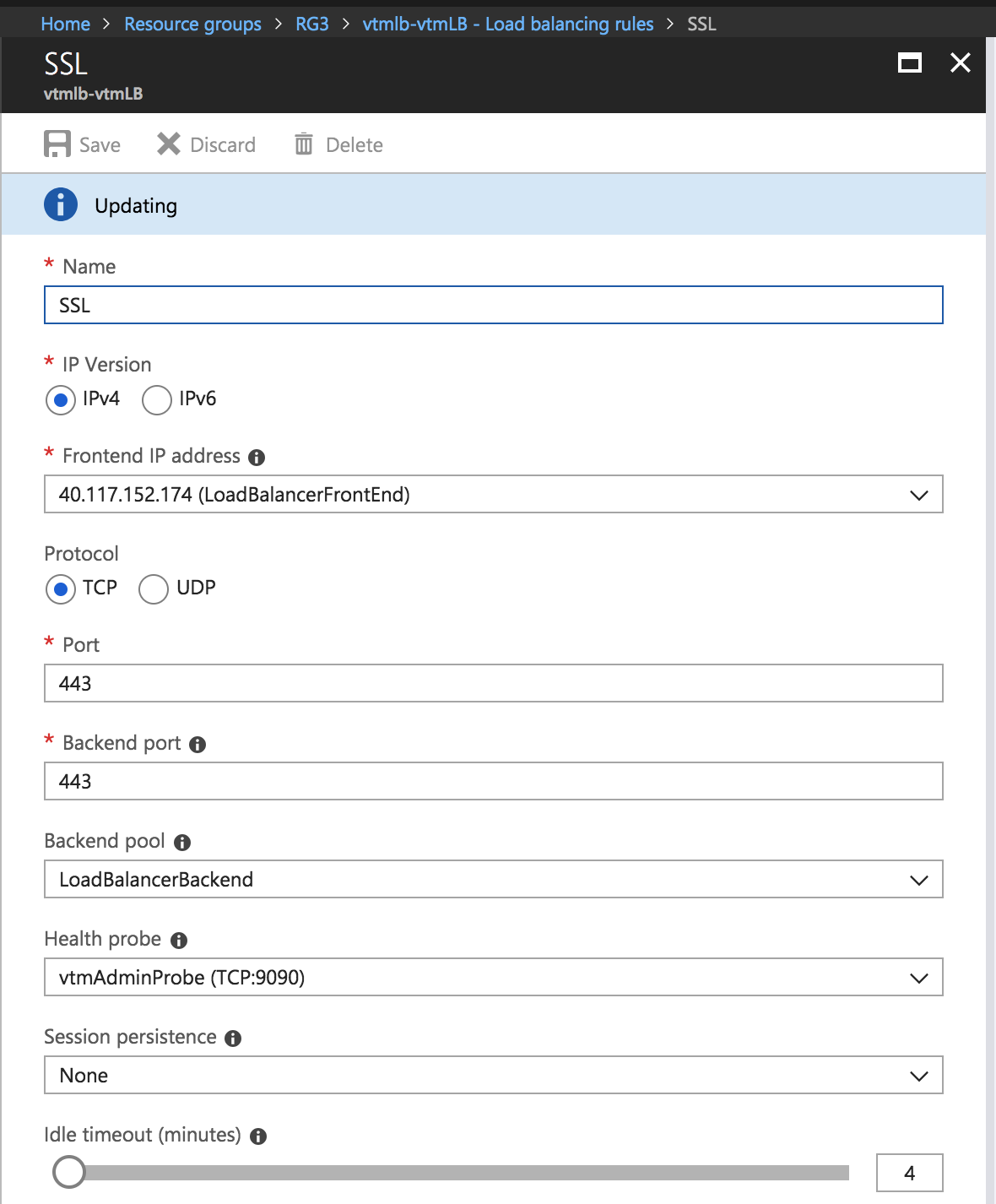
5.Configure the following settings for ESP and SSL traffic modes, and click OK:
•Name: Type a descriptive name for this rule.
•Protocol: Select your traffic protocol.
•Port: Enter the port number for your traffic.
•Backend Port: Set to the same value as Port.
•Session Persistence: Select “None”.
•Idle Timeout (minutes): Set to a timeout value suitable for your service.
•Floating IP (direct server return): Select “Disabled”.
6.In the resource group, click the name of the Network Security Group resource (typically named “<clustername>-vtmNSG”).
7.Click Inbound Security Rules and then click Add.
Inbound Security Rules
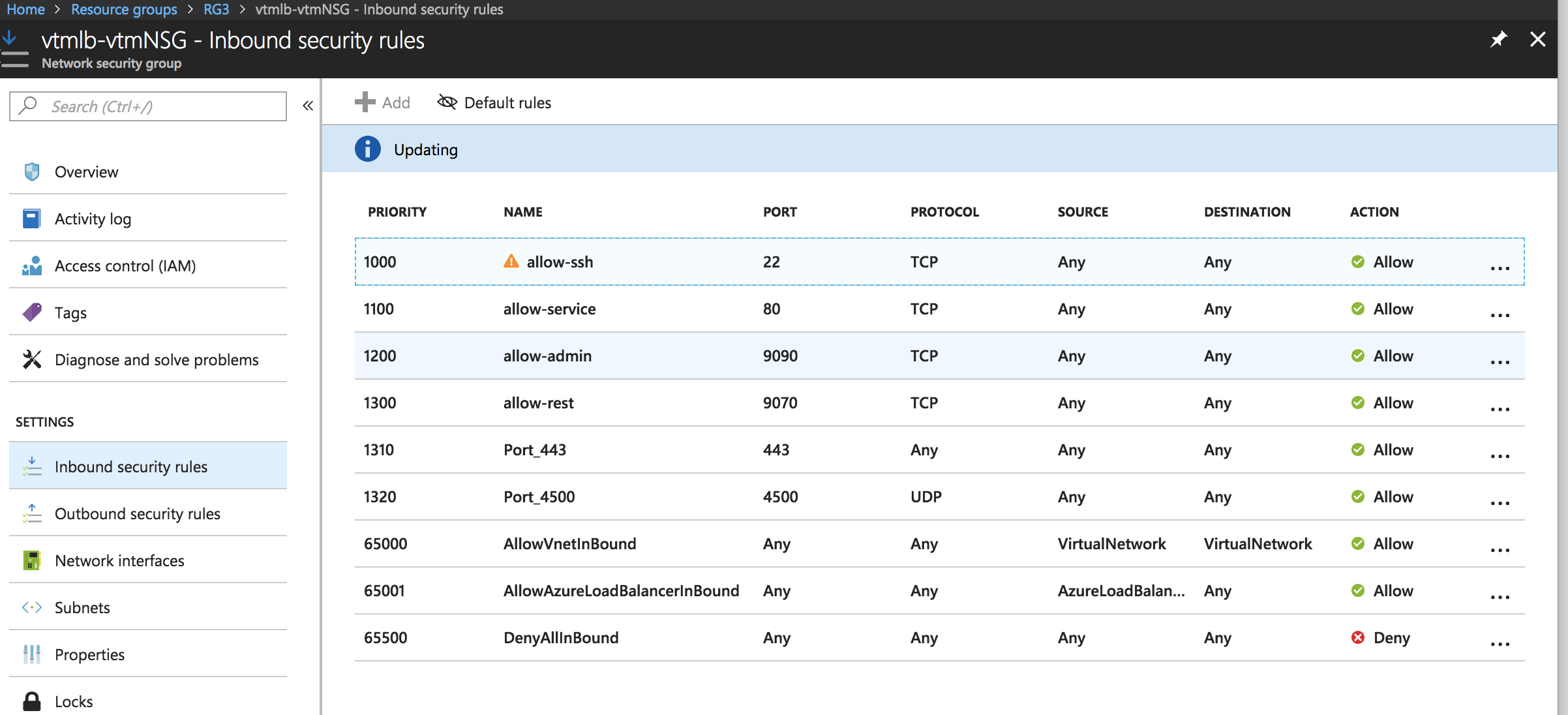
8.Configure the following settings:
•Name: Type a descriptive name for this rule.
•Priority: Enter the desired priority number. The higher the priority number, the lower the priority over other rules.
•Source: Select “Any”.
•Protocol: Select your traffic protocol.
•Source Port Range: Leave this setting as the default “*”.
•Destination: Select “Any”.
•Destination Port Range: Enter the port number or range for your traffic.
•Action: Select “Allow”.
9.Click OK to save the rule.