Deploying IPS on OpenStack Using Horizon Dashboard
Before proceeding with the IPS deployment, ensure that the necessary prerequisites are set up.
Ivanti recommends using standalone nodes or clusters of a maximum of two nodes behind a load balancer.
Ivanti Security Appliance (ISA)/ISA-V does not support clusters containing more than two nodes for IPS.
To deploy IPS on OpenStack, do the following:
1.Log in to the OpenStack.
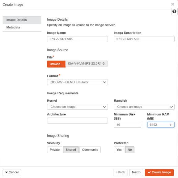
2.In the OpenStack dashboard displayed, select Project > Compute > Images and then create an image. For more information, see Create Image
.
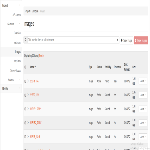
3.From the list of images displayed, click on Launch corresponding to the IPS KVM image you want to launch.
The following figure depicts the IPS VA Images screen:
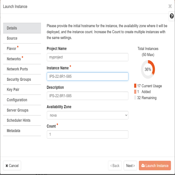
4.In the Launch Instance Details window, fill the following and then click Next.
•Instance Name: Specify host name of the IPS Virtual instance
•Description: Enter a brief description on this instance
•Availability Zone: Select the zone where the instance is deployed
•Count: Number of VM instances
The following figure depicts the Device Details screen:
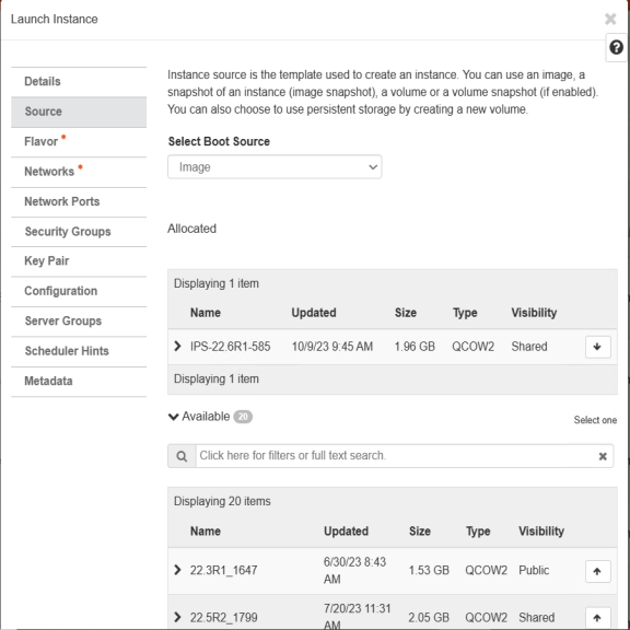
5.The Source window displays the details of the image used. Click Next.
The following figure depicts the Source Selection screen.
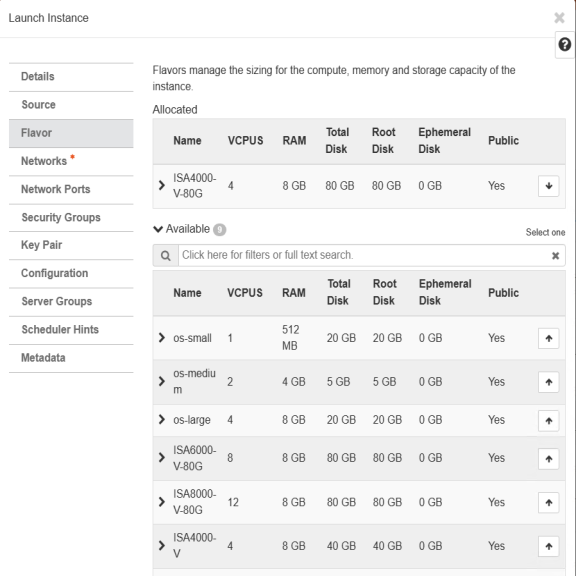
6.In the Flavor window, select required flavors of ISA-V (ISA4000-V, ISA6000-V, ISA8000-V) from the list based on the memory and storage capacity of the instance. Click Next.
The following figure depicts the Flavor Selection screen.
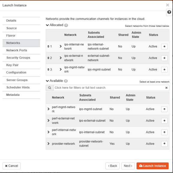
7.In the Networks window, select networks from the list that specifies internal, external and management subnets. IPS supports VM with 2-NIPS model and 3-NIPS model for deployment. Click Next.
The following figure depicts the Network Selection screen:
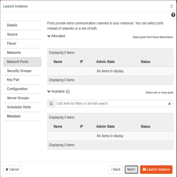
8.(Optional) Network Ports window. Click Next.
The following figure depicts the Network Ports Selection screen:
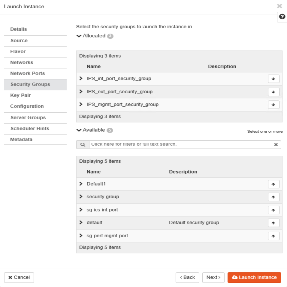
9.In the Security Groups window, select the required network security groups from the list for internal, external and management ports. Click Next. To create new security groups, refer Creating Required Security Groups for Internal, External and Management Ports
The following figure depicts the Security Groups Selection screen:
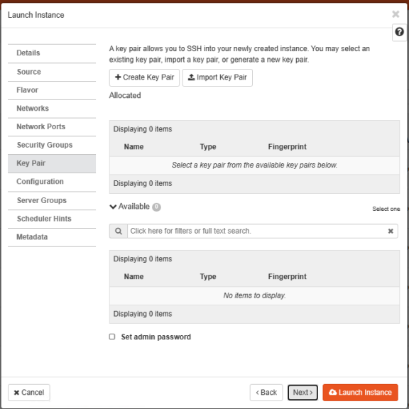
10.Key Pair is not used. Click Next.
The following figure depicts the Key Pair screen:
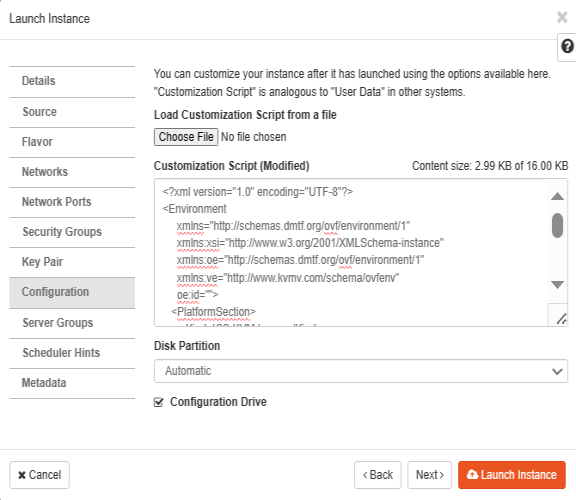
11.Click Choose File and import the file that contains the provisioning parameters in XML format OR paste the Customization script and do the required modifications. Select the Configuration Drive check box. The template file is available for ISA-V instance and click Launch Instance upon selecting the Configuration Drive option.
The following figure depicts the Configuration Script screen:
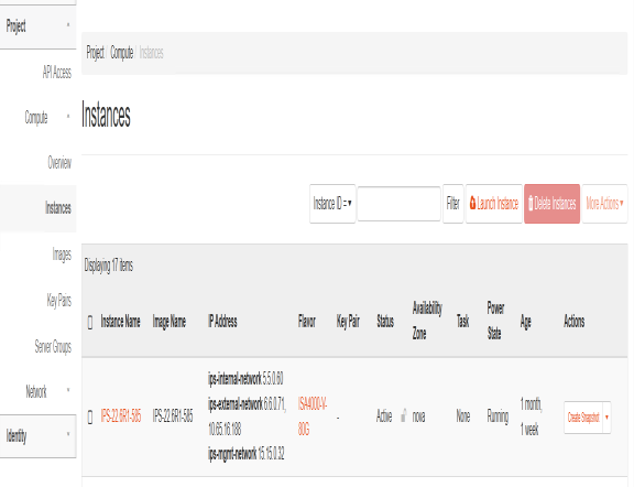
12.The Instances window lists all the IPS VA instances. The blue bar in the Task column shows the status of creation of the instance. This will take a few minutes.
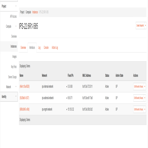
Open the created IPS VA instance by clicking on the Instance Name link.
The Interface tab shows the networks that are created.
The Log tab shows the log details of the device that is created.
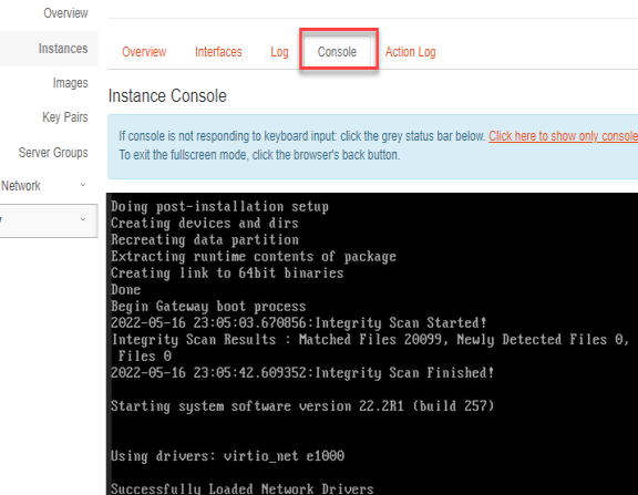
The console tab provides the virtual console to view the device coming up.
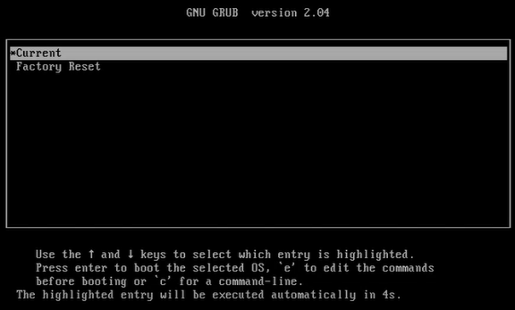
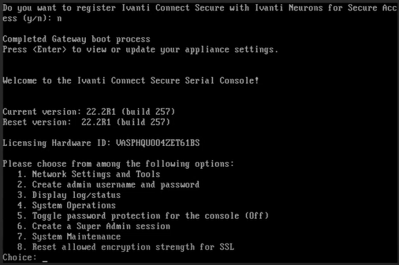
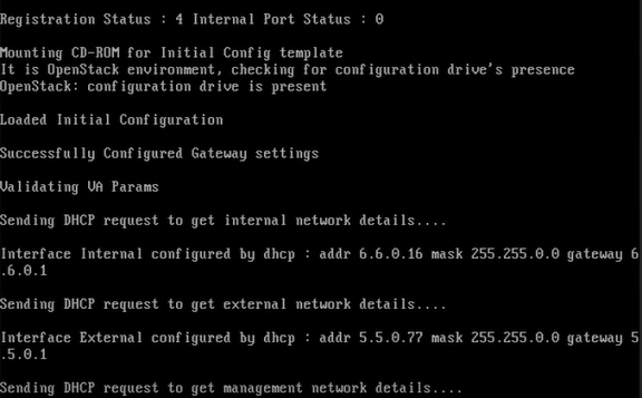
13.Next, the Internal and External interfaces are configured by DHCP (Zero touch configuration).
The following figure depicts the Internal and External Interfaces Configuration by DHCP screen:
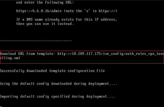
14.The Config URL is downloaded for initial configuration.
The following figure depicts the Download Config URL from Template screen: