Cluster Configuration
Admin UI Configuration
Creating a Cluster
To create a cluster:
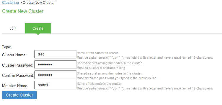
- Select System > Clustering > Create Cluster.

Settings
Actions
Cluster Name
Specifies a name to identify the cluster.
Cluster Password
Specifies the cluster password.
You need to enter the password again when specifying additional nodes to join the cluster. All nodes in the cluster use this password to communicate.
Confirm Password
Specifies the password that is confirmed.
Member Name
Specifies the name of this node in the cluster.
- Click Create Cluster. When prompted to confirm the cluster creation, click Create. After the device initializes the cluster, the Clustering page displays the Status and Properties tabs.

Configuring an Active/Active or Active/Passive Cluster
Once the cluster is created, you can modify the cluster properties to configure the cluster as an Active/Passive cluster. The cluster is created as an Active/Active cluster by default.
If IPv6 is required, then configure both the nodes with IPv6 settings before creating the cluster.
To configure the cluster properties:
- Click Properties tab of the cluster.

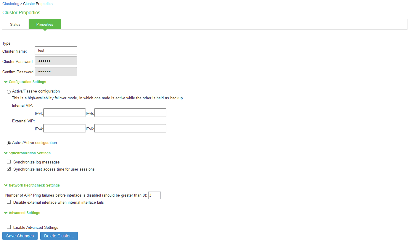
- Complete the configuration as described in the following table. Active/Active configuration is selected by default.
Settings
Actions
Cluster Name
Identifies the cluster.
Configuration Settings
Active/Passive configuration
Runs a cluster pair in active/passive mode. Then specify an internal VIP (virtual IP address) and an external VIP if the external port is enabled.
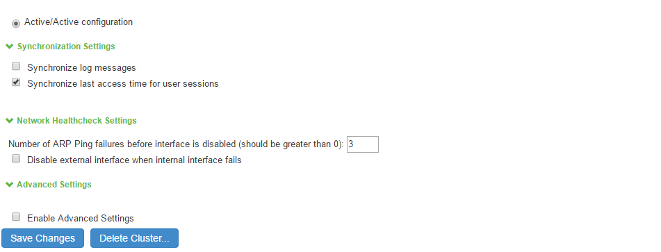
Active/Active configuration
(Default) Runs a cluster pair in active/active mode. This configuration runs a cluster of two or more nodes in active/active mode using an external load balancer.
To change a two-unit active/passive cluster to an active/active cluster with more than two nodes, first change the configuration of the two-unit cluster to active/active and then add the additional nodes.
Synchronization Settings
Synchronize log messages
Propagates all log messages among the devices in the cluster.
Synchronize last access time for user sessions
Propagates the latest user access information across the cluster.
- If your cluster node configurations diverge because of changes made to one node while another is disabled or unavailable, the system manages the remerging of the configurations automatically for up to 16 updates. Beyond the maximum number of allowable updates, you might need to intervene and remerge the configurations manually. In some instances, the system might be unable to remerge the configurations if there is not enough overlapping configuration information between two nodes to manage the internode communication.
- For example, for a two-node cluster in which the two nodes are partitioned from each other because of a network outage, if the internal network IP address of one of the nodes changes in one of the partitions, the two partitions are unable to rejoin, even when the network is repaired. In such a case, you must remerge the configurations manually.If you configure your cluster as active/passive, synchronize last access time for user sessions option is automatically selected.
Network Health Check Settings
Number of ARP Ping Failures
Specifies the number of ARP ping failures allowed before the internal interface is disabled.
Disable external interface when internal interface fails
Disables the external interface of the device if the internal interface fails.
Advanced Settings
Specifies the timeouts for the underlying cluster system. Do not change any values under this setting unless instructed to do so by Ivanti Global Support Center.
- Click Save Changes.
Adding Cluster Members
To add multiple nodes to a cluster:
- Select System > Clustering > Cluster status.
- Click Add Members Enter the node name and internal IP address.
- Modify or add the default internal netmask and internal gateway addresses, if necessary.
- Click Add.
- Repeat the process until you have added all the nodes.
- Click Save Changes to save the node configurations.

The system automatically enables the added nodes, even if they are unreachable.
- You configure the node-specific settings for the newly added node manually because binary import options are not useful.
- The only recommended binary import option into a cluster is “Import everything except network settings and licenses” from the Maintenance > Import/Export > Configuration page, which restores cluster-wide configuration (sign-in, realms, roles, resource policies etc.) from a backup binary file. As this option skips node-specific settings, you must perform step 2 manually to populate the newly joined node with the right set of node-specific settings.
License Server
If a license server needs to be configured on both the nodes of a cluster, then perform the following steps:
- Select Configuration >Licensing > Configure Server.
- Select the setting for Entire cluster.
- Configure the License server IP and preferred network.
- Click Save Changes.
Joining a Node to an Existing Cluster
The following procedure describes how to join a node to the existing cluster.
To join additional nodes to the cluster:
- From an existing cluster member, select the System > Clustering > Cluster Status tab and specify the node you want to add to the cluster.
- Select the System > Clustering > Join tab and enter the following information:
- The name of the cluster to join
- The cluster password you specified when defining the cluster
- The IP address of an active cluster member
- Click Join Cluster. When prompted to confirm joining the cluster, click Join.
The join cluster operation validates IPv4 and IPv6 settings for all the physical ports (internal, external, and management) against those present in the existing cluster. For example, the external port IPv6 settings present on Node-Y are compared against external port IPv6 settings that were specified for the Node-Y add member operation entered on the primary node (Node-X). If there is a mismatch, the join operation fails with an appropriate error message.

Deleting a Cluster
If you delete a cluster, all the nodes begin running as standalone systems.
To delete a cluster:
- Select the System > Clustering > Properties page.
- Click Delete Cluster.
- Click Save Changes.

Verifying the Cluster Status
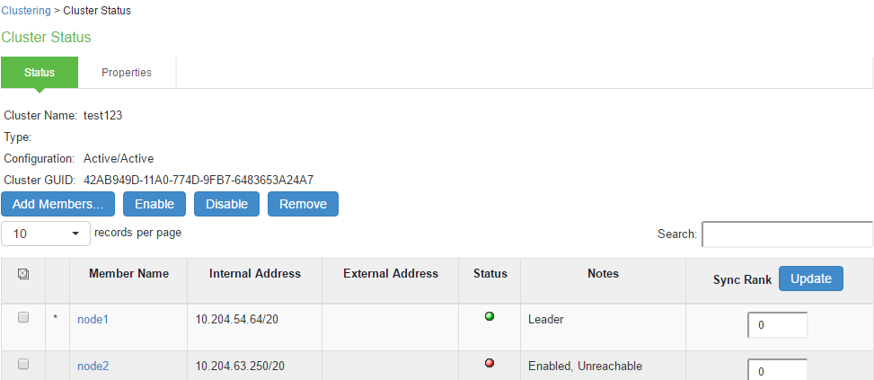
You can verify the cluster status on any node using System > Clustering > Cluster Status page. The list displays each node in the cluster along with its status. In an Active/Passive cluster, you can verify which node owns the VIP and you can force a manual fail over to the passive node by selecting the Fail-over VIP option.

|
GUI Element |
Description |
|---|---|
|
Status Information labels |
Displays the cluster name, type, configuration, internal VIP, and external VIP for an active/passive cluster. |
|
Add Members button |
Click this button to specify a node you intend to add to the cluster. You can add multiple nodes at the same time. |
|
Enable button |
Click this button to add a node that was previously disabled. When you add a node, all state information is synchronized on the node. |
|
Disable button |
Click this button to disable a node within the cluster. The node retains awareness of the cluster but does not participate in state synchronizations or receive user requests unless members sign in to the node, directly. |
|
Remove button |
Click this button to remove the selected node or nodes from the cluster. After removal, the node runs in standalone mode. |
|
Fail-Over VIP |
Click this button to failover the VIP to the other node in the active/passive cluster. Only available if cluster is configured as active/passive. |
|
Member Name column |
Lists all nodes belonging to the cluster. You can click on a node’s name to modify its name and network settings. |
|
Internal Address column |
Shows the internal IP address of the cluster member using Classless Interdomain Routing (CIDR) notation. |
|
External Address column |
Shows the external IP address of the cluster member using CIDR notation. Note that this column shows only the external IP address of the cluster leader unless you specify a different address for the node on its individual network settings page, which is accessible by clicking its name in the Member Name column. If you change the external IP address on the Network > Network Settings page, the change affects all cluster nodes. |
|
Status column |
Shows the current state of the node: Green light, Leader—The node is the active member of an active/active cluster and is handling user requests. Green light/enabled—The node is handling user requests and participating in cluster synchronization. Yellow light/transitioning—The node is joining the cluster. Red light/disabled—The node is not handling user requests or participating in cluster synchronization. Red light/enabled, unreachable —The node is enabled but because of a network issue, it cannot be reached. A node’s state is considered standalone when it is deployed outside of a cluster or after being removed from a cluster. |
|
Notes column |
Shows the status of the node’s connection to the cluster:OK—The node is actively participating in the cluster. ransitioning—The node is switching from the standalone state to the enabled state. Unreachable—The node is not aware of the cluster. A cluster member might be unreachable even when it’s online and can be pinged. Possible reasons include: its password is incorrect, it doesn’t have information about all cluster nodes, it’s configured with a different group communication mode, it is running a different service package version, or the machine is turned off. |
|
Sync Rank column |
Specifies the synchronization order for nodes when a node rejoins a cluster. Accepts sync ranks from 0 (lowest rank) to 255 (highest rank). The highest rank takes precedence. If two nodes have identical sync ranks, the alphanumeric rank of the member name is used to determine precedence. |
|
Update button |
Updates the sync rank after you change the precedence of the nodes in the Sync Rank column. |