Configuring 802.1X on IPS
This section covers the configuration for 802.1X authentication. It involves configuring the various elements necessary for performing 802.1X authentication between the endpoint and IPS.
802.1X authentication is also supported on external port. As a prerequisite, the Admin must enable Global Setting with Auth Traffic Control option. For configuration procedure, see AAA Traffic Management
Configuring Authentication Protocol Set
Authentication protocol is a method of defining how endpoints are authenticated through IPS. IPS supports a set of authentication protocols. You can configure sign-in policy with combination of authentication protocol set and associate them with realms to determine how endpoints connect and authenticate using 802.1X. The IPS supports a variety of EAP and non-EAP authentication methods to allow you to determine how endpoints authenticate. For example, you can use the default EAP methods with Ivanti Secure Access Client, or you can use different methods to permit authentication with different endpoints, such as third party 802.1X supplicants and IP phones.
For IPS agents (Ivanti Secure Access Client and Host Checker agentless access), authentication is supported through EAP-TTLS and EAP-PEAP as the outer protocols and EAP-JUAC (a proprietary protocol) by default.
EAP-TTLS first authenticates the server and sets up an encrypted Transport Layer Security (TLS) tunnel for secure transport of authentication information. Within the TLS tunnel, a second authentication protocol is used to authenticate the user. EAP-TTLS is the “outer” authentication, while the second protocol is the “inner” authentication.
The following is a list of supported EAP types:
EAP-PEAP uses server-side public key certificates to authenticate clients with server. The PEAP authentication creates an encrypted SSL / TLS tunnel between the client and the authentication server. The exchange of information is encrypted and stored in the tunnel ensuring the user credentials are kept secure.
- EAP-JUAC is a proprietary protocol that enables host check, firewall provisioning, and IP address restrictions.
- EAP-TTLS uses server-side certificates to set up authentication between clients and servers.
- EAP-SoH allows the endpoint to exchange state of health messages with IPS to assess endpoint qualification for passing Statement of Health rules in a Host Checker policy. It is used only with Windows native 802.1X supplicants.
- EAP-Generic Token Card (EAP-GTC) supports the use of authentication tokens.
- PAP supports the exchange of plaintext passwords.
- CHAP support includes MS-CHAP, MS-CHAPv2, EAP-Message Digest 5 (EAP-MD5), and EAP-MS-CHAPv2
- Password Authentication Protocol (PAP) with plain-text passwords.
- EAP Transport Layer Security (EAP-TLS) allows third party 802.1X supplicants to authenticate through a certificate authentication server.
IPS supports these authentication protocols as non-tunneled authentication methods as well as inner authentication methods, depending on the policies that you configure. You can configure protocol sets with or without EAP, with the exception of MD5, EAP-GTC, EAP-TLS, and EAP-SOH, which are supported only for EAP. To use EAP-SOH, you must use EAP-PEAP as an outer authentication protocol.
If you use a protocol set with inner and outer authentication, both protocols must match the inner and outer protocol that is configured for the endpoint.
IPS uses two default preconfigured protocol sets.
- 802.1X protocol set that is used by default with IPS agents.
- 802.1X-phones protocol set that is used for authenticating 802.1X IP phones.
Third-party supplicants cannot use the preconfigured 802.1X protocol set. For example, some switches can request authentication using CHAP, or EAP-MD5-Challenge. For such devices, you must define an authentication protocol set.
|
Outer |
Inner |
Basis |
Usage recommendation |
|---|---|---|---|
|
PAP [1] |
n/a |
Password |
Local auth server, Active Directory, LDAP [2] Cisco switch authentication |
|
CHAP [1] |
n/a |
Password |
Captive portal or authentication of switch administrators for HP ProCurve switch |
|
EAP-MD5-Challenge [1] |
n/a |
Password |
Captive portal or authentication of switch administrators, some IP phones |
|
MS-CHAP [1] |
n/a |
Password |
|
|
MS-CHAP-V2 [1] |
n/a |
Password |
|
|
EAP-MS-CHAP-V2 [1] |
n/a |
Password |
|
|
EAP-GTC [1] |
n/a |
Token |
|
|
EAP-TLS |
n/a |
User Certificate |
802.1X supplicant, some IP phones |
|
EAP-PEAP |
Third party 802.1X supplicant |
||
|
EAP-MS-CHAP-V2 |
Password |
Local or Active Directory server |
|
|
EAP-GTC |
Token |
802.1X supplicant |
|
|
EAP-TLS |
User Certificate |
||
|
EAP-JUAC |
Various |
Ivanti Secure Access Client |
|
|
EAP-SOH |
System Health |
Windows supplicant with Statement of Health Host Checker policy |
|
|
EAP-TTLS |
Ivanti Secure Access Client, other supplicant |
||
|
PAP |
LDAP authentication server |
||
|
CHAP |
|||
|
EAP-MD5-Challenge |
|||
|
MS-CHAP |
|||
|
MS-CHAP-V2 |
|||
|
EAP-MS-CHAP-V2 |
Local or Active Directory server |
||
|
EAP-GTC |
802.1X supplicant |
||
|
EAP-JUAC |
Ivanti Secure Access Client |
The following additional information is intended to help you understand the protocols that have been implemented for our 802.1x solution:
- Ivanti always uses EAP-TTLS/EAP-JUAC.
- EAP-TTLS, EAP-PEAP, and EAP-TLS are based on TLS and therefore secure. We recommend protecting other protocols by putting them into an EAP-TTLS or EAP-PEAP tunnel, if the supplicant supports one of these tunnels.
- With LDAP, there are 3 protocol possibilities:
- If the LDAP server is also an Active Directory server, configure the server on IPS as an Active Directory server, not as an LDAP server. On IPS, PEAP-MS-CHAP-V2 is enabled by default. You can also enable MS-CHAP and MS-CHAP-V2 if necessary.
- If passwords in the LDAP server are stored irreversibly hashed, CHAP family protocols will not work, only PAP and TTLS-PAP will work. On IPS TTLS-PAP is enabled by default. You can enable PAP if required, but this is the least secure protocol.
- Some LDAP servers allow you to store the passwords in clear text or reversibly encrypted. In this situation, all the CHAP family protocols will work.
During RADIUS authentication, if a user's password has expired then the user is prompted to change the password if the protocol is:
- EAP-MSChapV2
- PEAP with EAP-MSChapV2
- TTLS with EAP-MSChapV2
- TTLS with Non-EAP MSChapV2
- Plain Non-EAP MSChapV2
- EAP-JUAC
The following table summarizes additional usage guidelines.
- Password- The protocols that support password changing on IPS include JUAC, MS-CHAP-V2, EAP-MS-CHAP-V2, and EAP-GTC. If you use CHAP, PAP or MS-CHAP for a Layer 2 connection (for example, with an Active Directory Server), password changing is not supported through IPS.
- Expired passwords- You can direct users with expired passwords to a Web interface to access a default VLAN to allow users to log in with a clear text password and change their password.
- Password restrictions- Password restrictions (for example, password length) cannot be enforced if you use the CHAP family protocols for authentication.
- Default protocols for ivanti- The 802.1X protocol set is used by default for endpoints that connects Ivanti Secure Access Client. If you disable the JUAC protocol (a proprietary protocol) on Ivanti Secure Access Client IPS and have only the features of a standard third party supplicant.
To configure an authentication protocol set:
-
Select Authentication > Signing In > Authentication Protocols.
The default 802.1X protocol set is configured with EAP-TTLS and EAP-PEAP as primary (outer) authentication protocols.
EAP-JUAC, EAP-MSCHAP- V2 are used as inner authentication for EAP-PEAP.
EAP-JUAC, PAP, MSCHAP- V2, EAP-MS-CHAP-V2, or EAP-GenericTokenCard are used as inner authentication for EAP-TTLS.
To create a new protocol set, click New Authentication Protocol, or select the check box beside the existing 802.1X protocol set and click Duplicate.
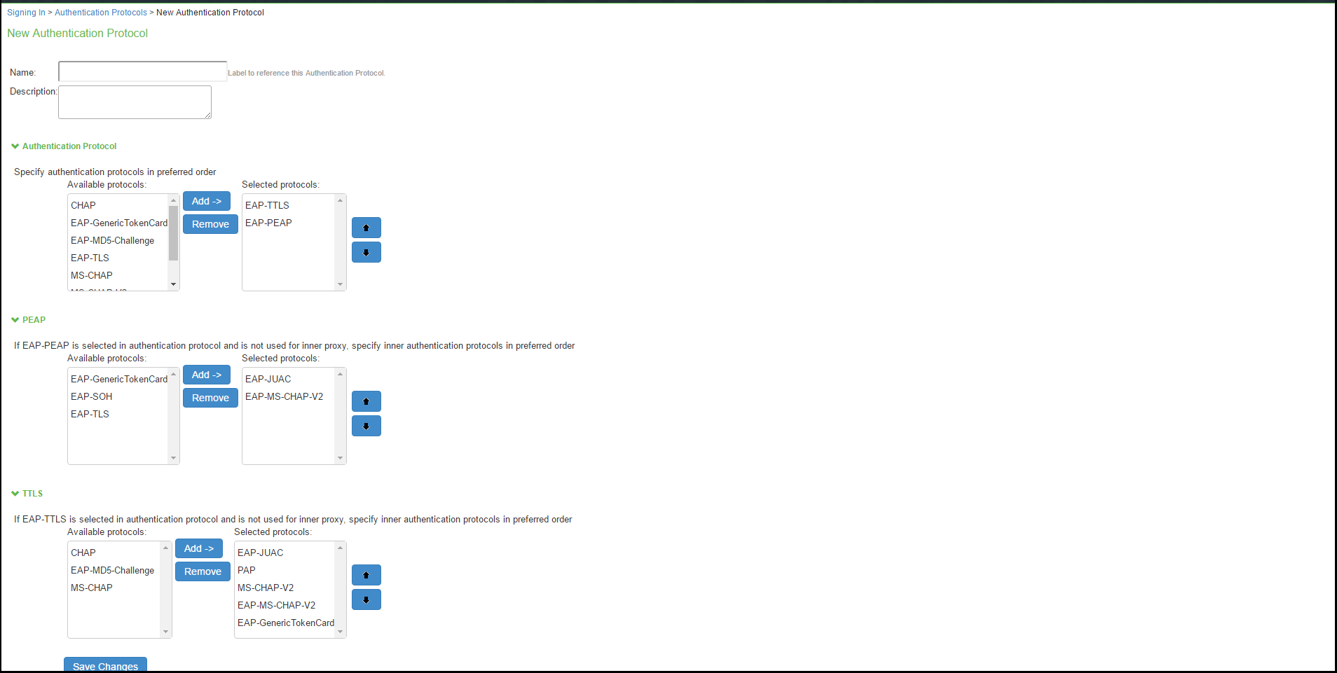
- Enter a name, and optionally a description for the new authentication protocol set. You select the protocol set by name when you create a sign-in policy.
- Under Authentication Protocol, select authentication protocol(s) from the Available Protocol list. Click Add.
- For non-tunneled protocols, create an authentication protocol set, which includes CHAP, PAP or EAP-MD5 Challenge.
- If you select EAP-PEAP as the main authentication protocol, under PEAP select an inner authentication protocol from the Available Protocol list. Click Add.
- If you select EAP-TTLS as the main authentication protocol, under TTLS select an inner authentication protocol from the Available Protocol list. Click Add.
If you are using inner RADIUS proxy, do not select an inner protocol with EAP-PEAP or EAP-TTLS.
- Click Save Changes to save your selections. When you configure a sign-in policy, you associate this authentication protocol set with an authentication realm.
Creating and modifying the sign-in policy
Sign-in policies define both the URLs that users and administrators use to access the network and to view the sign-in pages. IPS has two types of sign-in policies—one for users and one for administrators. When you configure sign-in policies, you associate realms, sign-in pages, and URLs that are provided for users when they first log in.
To modify the authentication protocol set used by a specific authentication realm:
- Select Authentication > Signing In > Sign-In Policies and click New URL.
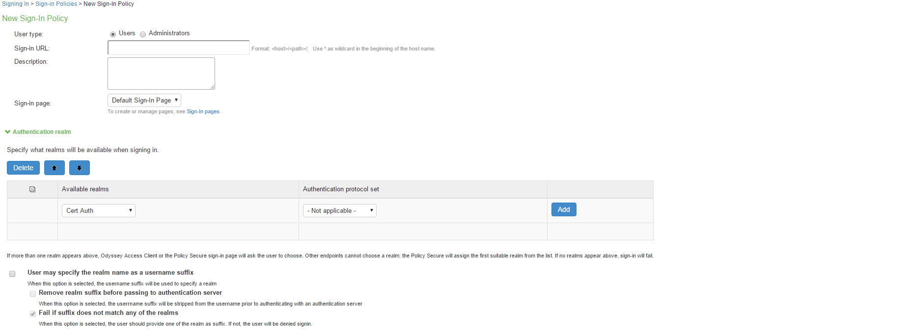
- Under Authentication realm, add a new realm or modify an existing realm.
- Select the desired authentication protocol set.
- Click Save Changes.
Configuring a Location Group
Location groups let you organize or logically group network access devices by associating the devices with specific sign-in policies. Sign-in policies provide a way to define and direct independent access control policies with the network. For example, you can create location group policies to logically group the switch/WLC in each building at a corporate campus. You can also use location group policies to specify a special realm for MAC address authentication.
To configure a location group:
- Create a sign-in policy to associate with the location group.
- Select Endpoint Policy > Network Access > Location Group.
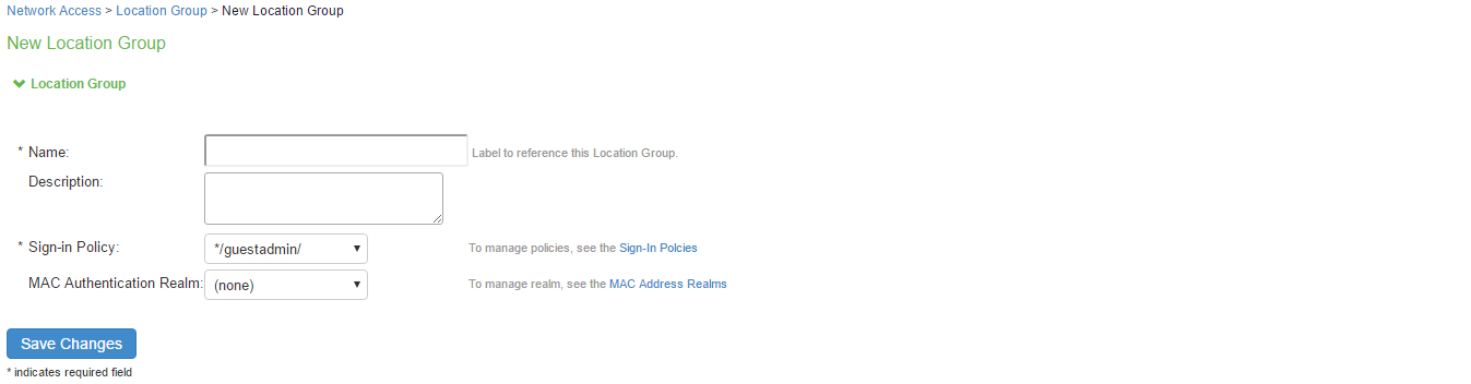
- On the New Location Group page, enter a name to label this location group and optionally a Description.
- For Sign-in Policy, select the sign-in policy associate with the location group.
- Click Save Changes.
Location groups allows you to block Layer 2 endpoints in specific locations from using particular authentication protocols, realms, and roles. For example, you can block endpoints in unsecure locations from accessing sensitive roles. However, RADIUS clients should not be placed in insecure locations. To ensure that RADIUS clients are not compromised and do not violate these policies, all the network RADIUS clients should be securely protected.
Configuring the network access device as a RADIUS Client
A RADIUS client policy specifies the information required for an 802.1X network access device to connect as a RADIUS client of the IPS.
When you select the device’s make and model in a RADIUS client policy, you are selecting a dictionary file that contains the vendor-specific attributes (VSAs) for that device. Whenever IPS receives a RADIUS packet from that device, it consults the dictionary file for any nonstandard attributes that it encounters in the packet. If you do not know the make and model of a device, you can use the standard RADIUS attributes by choosing the Standard RADIUS setting in a RADIUS client policy.
In addition to the configuration on IPS, you must configure the NAD with information about IPS, including:
- IP address
- Shared secret specified in the RADIUS client policy for the device
To configure a RADIUS client:
- Select Endpoint Policy > Network Access > RADIUS Client.
- Click New RADIUS Client.
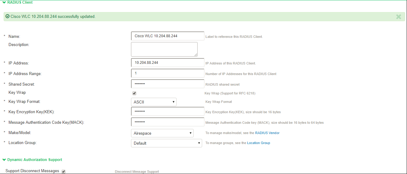
- On the RADIUS Client page, enter a name to label the RADIUS client. You can assign any name to a RADIUS client entry, use the device's SSID or IPv4/IPv6 address to avoid confusion.
- (Optional) Enter a purpose or description of the configuration so that other users are aware of it.
- Enter the IPv4/IPv6 address of the switch.
If you specify the Switch Address as IPV6, IPS will allow Ivanti Secure Access Client to connect only using Client’s IPv6 address in 802.1x Connection Type.
- (Optional) For IP Address Range, enter the number of IP addresses in the IP address range for the switch/WLC, starting with the address you specified for IP Address. You can specify a range up to a maximum of 32,768 addresses.
- For Shared Secret, enter the RADIUS shared secret. A RADIUS shared secret is a case-sensitive password used to validate communications between IPS and NAD. IPS supports shared secrets of up to 127 alphanumeric characters, including spaces and the following special characters:
~!@#$%^&*()_+|\=-‘{}[]:”’;<>?/., - For Make/Model, select the make and model of the NAD. The make/model selection tells IPS which dictionary of RADIUS attributes to use when communicating with this client.
Note that Ruckus Request Password needs to be configured only for SmartZone Guest Access. - (Support for RFC 6218: Cisco/Airespace Switches). If you are configuring a new RADIUS authentication server and want to enable AES key wrap, which makes the shared secret between the controller and the RADIUS server more secure, follow these steps:
- Enable the Key Wrap checkbox.
- From the Key Wrap Format drop-down list, choose ASCII or HEX to specify the format of the AES key wrap keys: Key Encryption Key (KEK) and Message Authentication Code Key (MACK)
- Enter the 16-byte KEK used for encrypting the key generated by the server
- Enter the 16-64 bytes MACK used for authenticating the messages.
AES key wrap is designed for Federal Information Processing Standards (FIPS) customers and requires a key-wrap compliant RADIUS authentication server.
- For Location Group, select the location group to use with this NAD.
- Under Dynamic Authorization support, Select the Support Disconnect Messages check box to send disconnect messages to supplicants if access is no longer authorized. If this check box is selected, a disconnect request is sent to the NAD any time a session is deleted. IPS can also send disconnect messages upon a role event that includes a VLAN change or a change in RADIUS attributes.
- Select Support CoA Messages to enable CoA messages and disconnect messages support for the client. Ensure that Ivanti Secure Access Client is configured with EAP-JUAC in EAP-TTLS inner protocol as most preferred protocol.
RADIUS CoA feature provides a mechanism to change the attributes of an authentication, authorization, and accounting (AAA) session after it is authenticated. Using the existing session, RADIUS CoA allows devices to change the VLAN/ACL for the endpoint based on roles. CoA works on role mapping associated with every user. As the device state changes, the user is put in to various roles based on the Host Checker assessment or compliance check. During the dynamic assessment, CoA requests such as filter-id or any other return attributes that suites the role is sent to the NAD to provide the required access for the device. IPS receives CoA-NAK request if the NAD is not able to apply filter-id or any other return attributes. - (Optional) Enter a new Dynamic Authorization Port (Default port is 3799). The default port might vary depending on the manufacturer. NAD listens to UDP port to receive RADIUS CoA messages from IPS.
- Click Save Changes.
Configuring Role and Role Mapping
IPS access management framework evaluates authentication requests to match endpoints to roles. You must configure user roles for the various types of endpoints authenticated.
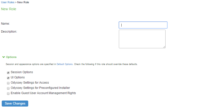
To create a user role:
- Select Users > User Roles.
- Click New Role.
- Complete the name and description configuration and then save the configuration.
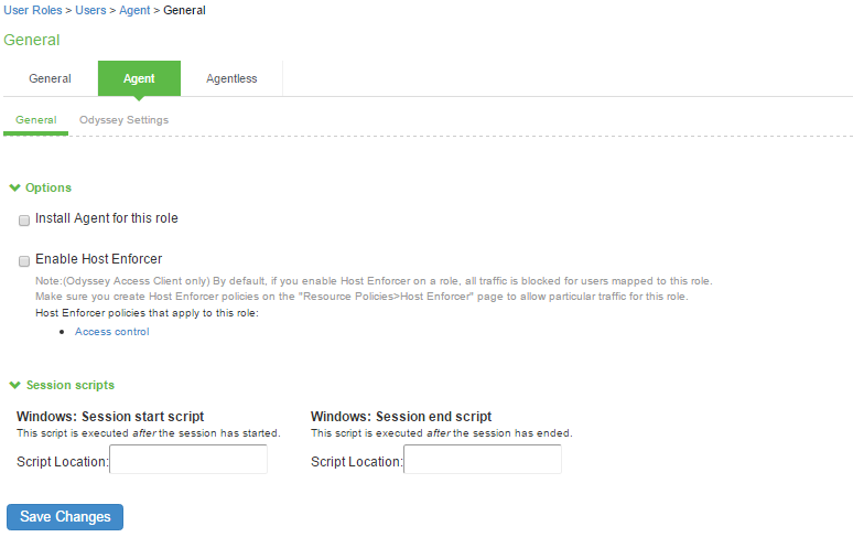
- Click Agent and deselect agent options and then save the configuration.
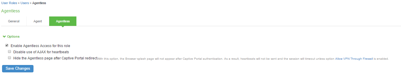
- Click Agentless and enable agentless access and then save the configuration.
Role mapping rules define how endpoints are assigned to roles.
To configure the role mapping rules for User Realms:
- Select Users > User Realm.
- Click New to display the User Realm configuration page and create a user realm.
- Click the Role Mapping tab to display the role mapping configuration page for the realm.
- On the role mapping configuration page, click New Rule to display the role mapping rule configuration page.
- (Optional) For Name, enter a name to label this role mapping rule.
- Select the rule from the Rule based list and provide the appropriate details.
- Select the appropriate role and click Add.
- Click Save Changes to save the configuration.
Configuring RADIUS Attributes Policies
This section describes the configuration information for RADIUS return attributes policy that is applied on switch, request attribute policy, which can be used along with sign-in policies for realm selection, policy realm restrictions, and authentication/accounting reporting for RADIUS authentication events.
Configuring RADIUS Return Attributes
RADIUS attributes policies sends the return list of attributes to an 802.1X switch. For example, you can specify which VLAN endpoints must be used to access the network. You can also configure other functions on a NAD's port based on the role assigned to the user who is currently using that port. For example, a Switch might let you use return list of attributes to configure Quality-of-Service (QoS) functions (Bandwidth or Priority) on the device's port based on the current user's role.
A return list is a set of attributes that IPS returns to the NAD after authentication. The return list usually provides additional parameters that the NAD needs to complete the connection. Return list attributes are authorization configuration parameters.
In the RADIUS attributes policy, you can select RADIUS attributes by name from a predefined list. For each attribute, you specify values using strings or numbers. By default, IPS sends a session timeout value on all RADIUS accepts that is equal to the timeout value of the configured session length. You can bypass the default timeout.
To configure a RADIUS attributes policy:
- Select Endpoint Policy > Network Access > RADIUS Attributes.
- Click New Policy.
- On the New Policy page, enter a name for the policy.
- (Optional) For Description, enter a description for the policy.
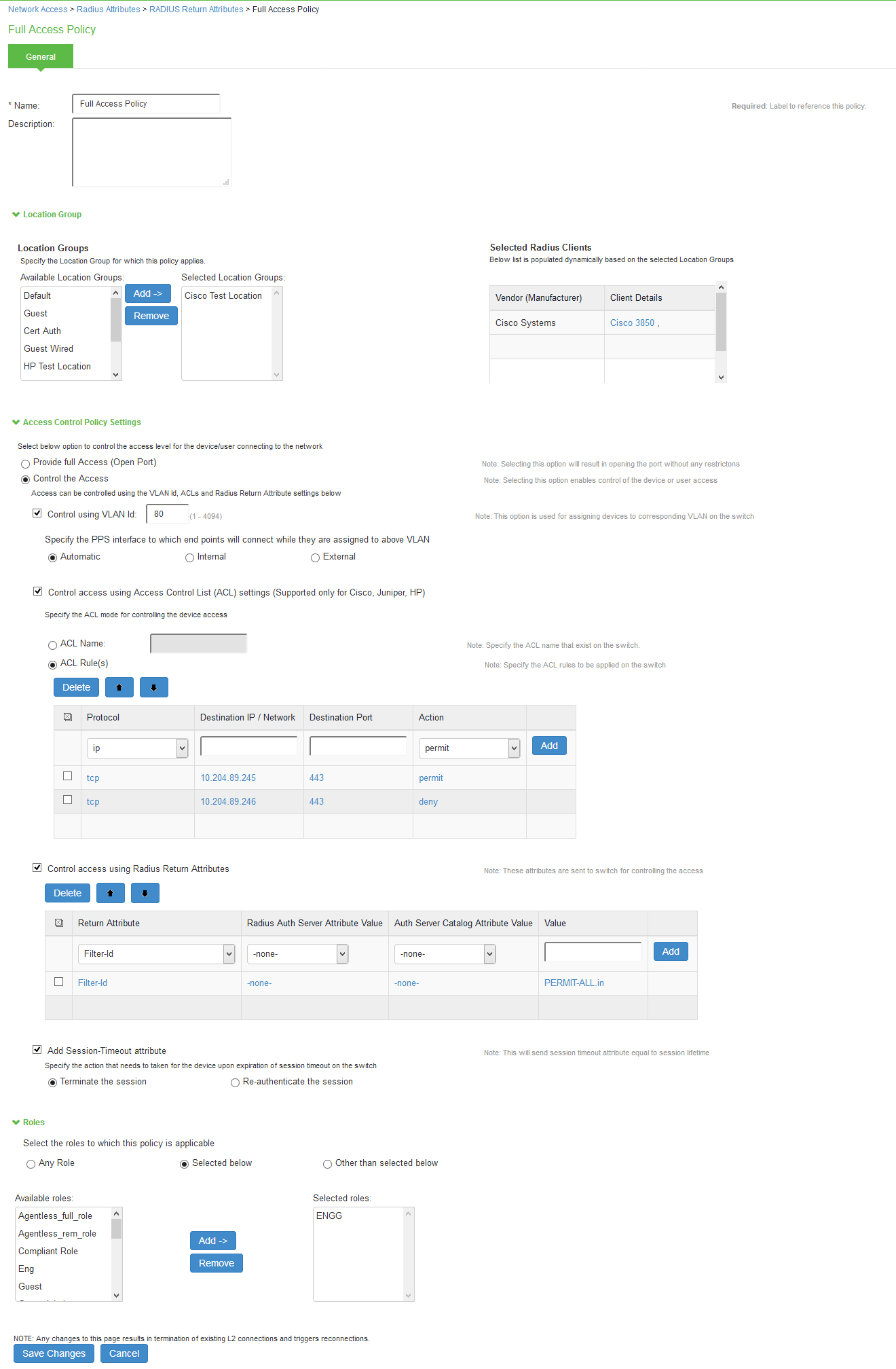
- Under Location Group, select the location groups to which you want to apply this policy, and click Add. To apply the policy to all location groups, do not add any location groups and use the default setting (all) listed in the Selected Location Groups list. The selected Radius clients table is dynamically updated based on the selected Location Groups.
-
Under Access Control Policy Settings, select from the following options:
- Provide full Access (Open Port)-Check this option if you do not want to assign endpoints to a VLAN or return any RADIUS attributes. Selecting this check box disables all other RADIUS Attributes options.
- Control the Access-Select this option to control access using VLAN ID, ACLs and RADIUS return attributes.
Control using VLAN Id: Enter the VLAN ID (1-4094) used for assigning devices to corresponding VLAN on the switch.
- For Interface, specify IPS network interface that endpoints affected by this policy to use to connect to IPS:
- Automatic (use configured VLANs)-Select this option to use VLAN tagging. You must also connect the internal interface to the trunk port on a VLAN-enabled Switch that sees all the VLAN traffic.
- Internal- Select this option if the endpoints using this RADIUS attributes policy should use the IP address of the internal interface.
- External-Select this option if the endpoints on the configured VLAN should use the IP address of the external interface.
Control access using Access Control List (ACL) settings (Supported only for Cisco, Juniper, HP)
- Specify the ACL Name for controlling the device access or specify the ACL Rule to be applied on the Switch.
- Select the Protocol (IP/TCP/UDP/ICMP), Destination IP/Network Mask, Destination Port, Action (Permit/Deny) and Click Add.
The supported RADIUS clients for ACL mode are Cisco, Juniper, and HP switches. If there are any unsupported clients listed in the Supported RADIUS client table then the ACL configuration will be disabled.
Control Access using Radius Return Attribute-Select this option to specify the return attributes you want sent to the Switch/WLC.
- Select the return attribute to send from the attribute list. Enter the value for the selected attribute and then click Add.
- You can specify multiple return attributes and values for this policy.
- To rearrange the order in which you want to send the return attributes, select the check box next to the attribute name and then click the up or down arrow.
- To delete an attribute, select the check box next to the attribute name then click Delete.
If both (user/policy) have the same attributes, preference will be given to User attribute values.
Add Session-Timeout attribute-Select this option to specify the action (Terminate the session or reauthenticate the session) taken upon on the expiration of session timeout.
- Under Roles, specify:
- Any role-To apply the policy to all users.
- Selected roles-To apply this policy only to users who are mapped to roles in the Selected roles list. You must add roles to this list from the Available roles list.
- Roles other than those selected below-To apply this policy to all users except for those who map to the roles in the Selected roles list. You must add roles to this list from the Available roles list.
- Click Save Changes.
VLAN change using CoA is not supported with Cisco Switches. It is recommended to use RADIUS disconnect for VLAN change.
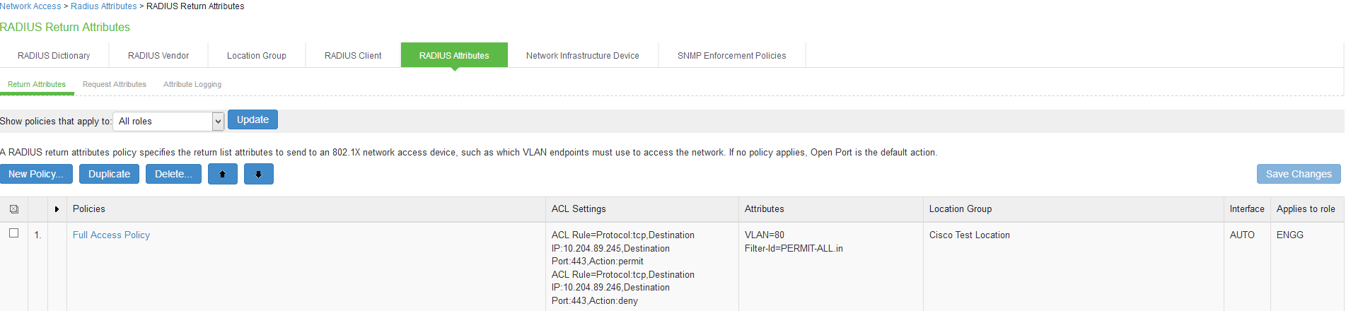
Example configuration for parsing ACL rule name (HP, Cisco, and Juniper)
|
IPS ACL rule configuration |
tcp | 10.xx.xx.x | 443 | Permit |
|---|---|
|
HP 2920 expansion |
HP-nas-filter-rule=permit in tcp from any to 10.xx.xx.x 443 |
|
Cisco 3850 expansion |
ip:inacl#100=permit tcp any host 10.xx.xx.xxx eq 443 |
|
Juniper - EX 2200 expansion |
Juniper-Switching-Filter='Match Destination-ip 10.xx.xx.x Ip-protocol 6 Destination-port 443 Action allow' |
Example configuration for parsing ACL name (HP, Cisco, and Juniper)
|
Vendors |
Cisco |
HP |
Juniper |
|---|---|---|---|
|
RADIUS VSA |
filter-id |
filter-id |
filter-id |
|
Example- RADIUS VSA value |
<ACL-NAME>.in |
<ACL-NAME>.in |
ACL-Name |
Example: RADIUS Attribute Policies
You can configure RADIUS attributes in the IPS to send return list attributes to an 802.1X network access device. For example, you can specify which VLAN the endpoint must use to access the network. You can also configure other functions on the network devices port based on the role assignment. For example, a particular Switch might let you use return attributes to configure QoS functions (bandwidth, priority, or both) on the device port based on the user role.
The example illustrates a RADIUS attribute policy to specify VLANs for endpoints, using the following steps:
- If you are using more than two VLANs, connect IPS internal interface to the trunk port on a VLAN-enabled switch that detects all the VLAN traffic.
- You can also configure a RADIUS attributes policy with the Automatic setting, which enables IPS to take advantage of VLAN tagging. When connected to a trunk port on a VLAN-enabled switch, IPS detects traffic from all VLANs.
- You can also configure routing on the network to enable endpoints to access IPS over the network. In this case, you must configure RADIUS attributes policies with the VLAN IDs you are using for endpoints, but you do not need to configure any VLAN ports on IPS.
The following figure illustrates an example of using a RADIUS attributes policy to specify VLANs for endpoints.
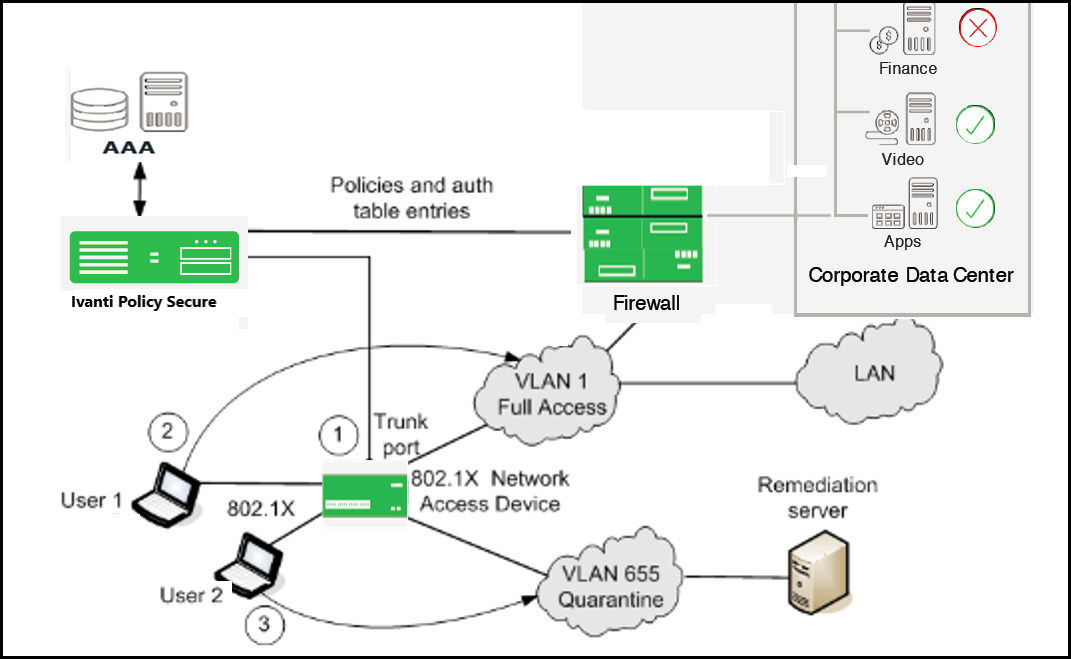
- If the user 1 is authenticated and the endpoint complies with Host Checker security policies, then the user is assigned a role on the Full Access VLAN that allows full network access and access to protected resources.
- If user 2 is authenticated but the endpoint does not comply with Host Checker security policies. The user is assigned a role on the Quarantine VLAN that only allows access to a remediation server.
Example: Configuring various RADIUS Return Attribute Policies
Configuring VLAN Assignment using RADIUS return Attribute Policy
This configuration describes how to send VLAN assignment to the Switch/WLC by returning RADIUS attributes.
- Select Ivanti Policy Secure > Network Access > RADIUS Return Attributes.
- Under Access Control Policy Settings, select Control the Access > Control using VLAN ID.
- Specify a VLAN ID.
Configuring VLAN Assignment along with other RADIUS return Attributes Policies
This configuration describes how to send VLAN assignment and other attributes to the Switch/WLC by returning RADIUS attributes.
- Select Ivanti Policy Secure > Network Access > RADIUS Return Attributes.
- Under Access Control Policy Settings, select Control the Access > Control using VLAN ID.
- Specify a VLAN ID.
- Select Control Access using Radius Return Attributes.
- Select the attribute you want to return from the Attribute list.
- For Value, specify an attribute value.
Configuring Filter-ID using RADIUS Return Attribute Policy
This configuration describes how to send Filter-ID to switch/WLC by using the Filter-ID return attribute.
- Select Endpoint Policy > Network Access > RADIUS Return Attributes.
- Under Access Control Policy Settings, select Control Access using Radius Return Attributes.
- Select Filter-ID from the Attribute list.
- For value, specify the policy name.
- Configure the filter on the NAD.
Configuring VLAN Assignment in a multi-vendor Switch Environment
This configuration describes how to send VLAN assignment in a multi-vendor switch environment that includes switch/WLC from different vendors. For example, you might have one type of switch that supports RADIUS tunnel attributes only, a second type of switch that supports the Filter-ID return attribute only, and a third type of switch that supports both.
- Select Endpoint Policy > Network Access > Location Group and create a location group policy for each type of NAD.
- Create a location group policy for switches that support RADIUS tunnel attributes only.
- Create a second location group policy for switches that support the Filter-ID return attribute only.
- Create a third location group policy for switches that support both RADIUS tunnel attributes and the Filter-ID return attribute.
- Select Endpoint Policy > Network Access > RADIUS Client. Then, follow these steps to create a RADIUS client policy for each type of NAD and associate each RADIUS client policy with the appropriate location group.
- Create a RADIUS client policy and specify a make/model for Make/Model that supports the RADIUS tunnel attributes. Associate this policy with the location group policy for switches that support RADIUS tunnel attributes only.
- Create a second RADIUS client policy and specify a make/model that supports the Filter-ID return attribute. Associate this policy with the location group policy for switches that support the Filter-ID return attribute only.
- Create a third RADIUS client policy and specify a make/model that supports the both RADIUS tunnel attributes and the Filter-ID return attribute. Associate this policy with the location group policy for switches that support both RADIUS tunnel attributes and the Filter-ID return attribute.
- Select Endpoint Policy > Network Access > RADIUS Attributes and then follow these steps:
- Create a RADIUS Attributes policy that specifies only the VLAN option and a value for VLAN ID. Associate this policy with the location group policy for switches that support RADIUS tunnel attributes only.
- Create a second RADIUS Attributes policy that specifies only the Filter-ID option from the Attribute list and a policy name for Value. Associate this policy with the location group policy for switches that support the Filter-ID return attribute only.
- Create a third RADIUS Attributes policy that specifies both the VLAN option and a value for VLAN ID, and the Filter-ID option with a policy name for Value. Associate this policy with the location group policy for switches that support both RADIUS tunnel attributes and the Filter-ID return attribute.
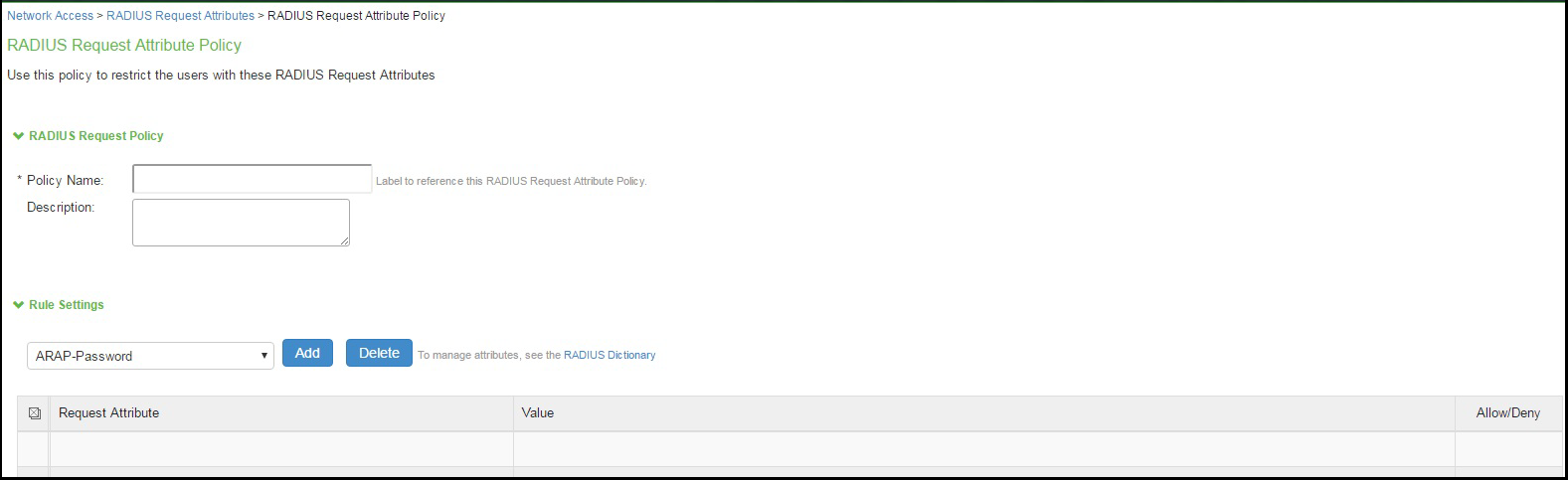
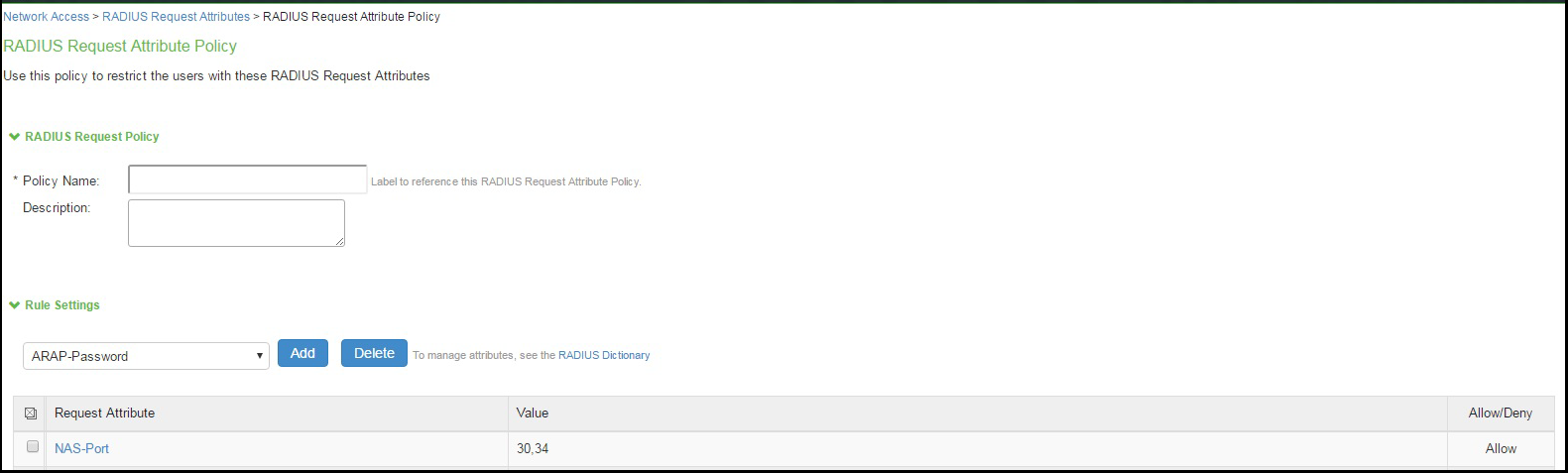
Configuring RADIUS Request Attribute Policies
RADIUS request attribute policies allows you to enforce the authentication requests based on information in the RADIUS packet. RADIUS request attribute policies consist of rules. Each rule consists of one attribute and some number of values. The type of value depends on the type of rule chosen. For example, if you select a rule with the User-Name attribute, you enter a string.
- RADIUS request attribute policy names must be unique.
- Each request page includes guidance on what type of value is expected.
If you select a rule with the Login-IP-Host attribute, you enter an IP address and an optional netmask. The default netmask value is 255.255.255.255. The value of the attribute must fall within the specified IP address and netmask to pass the policy.
The RADIUS Access-Request attribute policy performs two tasks:
- Determines communication with the RADIUS client, indicating that the specified attributes must be sent in the Access-Request message.
- Parses the attribute-value pairs that are sent in the Access-Request message against the allow/deny rules you configure. The result of rules processing can be enforced in a realm restriction.
To configure a RADIUS Request attribute policy:
- Select Endpoint Policy > Network Access > RADIUS Attributes > Request Attributes to display the configuration summary page.
- Click New to display the policy configuration page.
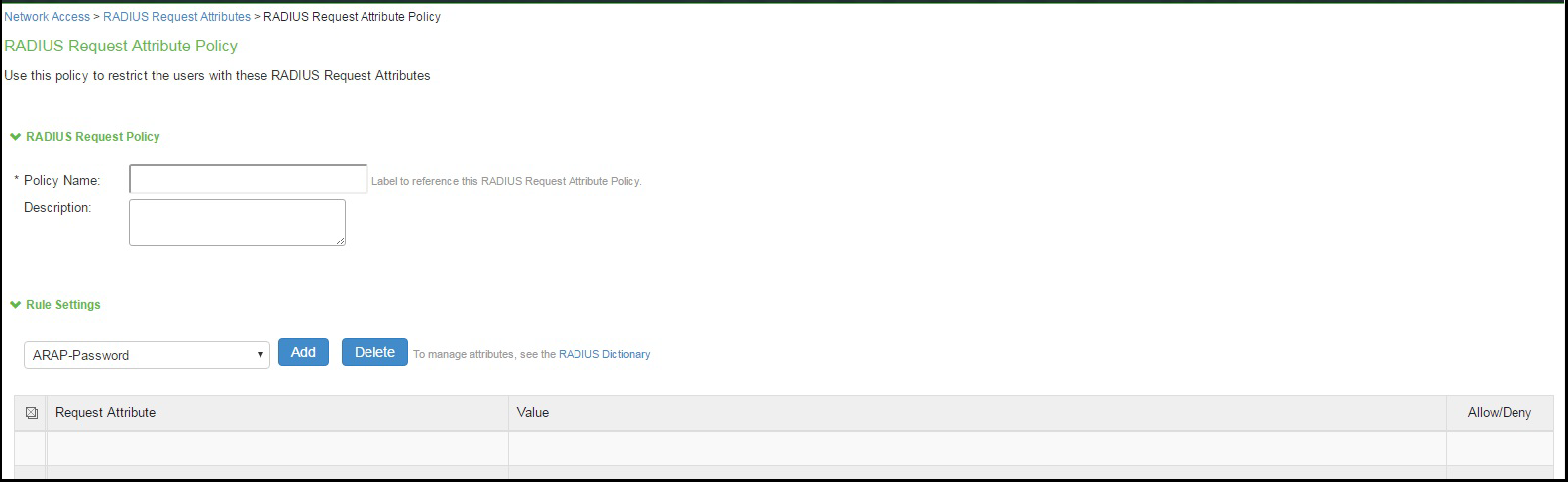
- Specify a policy name and description.
- Under Rule Settings, select a RADIUS Access-Request attribute and click Add to display the rule configuration page.
- Complete the rule configuration as described below.
Settings
Guidelines
Add
Specify values or a pattern for rule matching. The system parses wildcards and value expressions as follows:
String-An asterisk (*) matches multiple characters and a question mark (?) matches a single character.
Integer-An asterisk (*) matches any value. You can use a hyphen to specify a range of values, for example 1-99.
Hexadecimal-An asterisk (*) matches any value.
Click Add again to add more attribute values, as necessary. The result of adding multiple values is a comma-separated list.
Allow / Deny
Select Allow to permit access to matching sessions.
Select Deny to deny access to matching sessions.
- Save the rule configuration and return to the policy configuration page.
Configuring a RADIUS Request Policy Realm Restriction
RADIUS request attribute policies can be assigned with a realm restriction. Any authentication request that comes from a realm with attribute policy requirements sends the RADIUS attributes specified in the policy, otherwise the authentication request is not granted. If multiple rules are configured in a policy, then all rules in the policy must pass otherwise the authentication fails.
If a user authentication fails based on the RADIUS request attribute policy, a user event log message is displayed. Debug logs allow the administrator to determine that a user met the policies, or indicate that the user failed a RADIUS return attribute policy.
To configure a RADIUS Request realm restriction:
- Select Endpoint Policy > Network Access > RADIUS Attributes > Request Attributes to display the configuration summary page.
- Click New to display the policy configuration page.
- Complete the configuration as described in the following table.
- Click Save.

|
Settings |
Guidelines |
|---|---|
|
Policy list |
Use the Add and Remove buttons to create a policy list. The available policies are populated by the RADIUS request policies configured in the prior procedure. |
|
Allow access to realm if any one of the selected policy is passed. |
This option determines what happens when multiple policies match. Select this option to allow access to the realm if any of the matching policies allow access (Ignoring any matching deny policies). Do not select this option if you want to deny access if one of the matching policies deny access (Ignoring any matching allow policies). |
Configuring RADIUS Attribute Logging
You can configure IPS to enable or disable authentication reporting for RADIUS authentication events. Using this feature you can obtain a granular record of authentication attempts using configurable and detailed authentication reports.
You can selectively choose events to record based on both successful and unsuccessful authentication attempts. If you select an attribute to be recorded and the value is not present in the authentication request/response, an entry is made in the debug log and in the RADIUS log. You can also specify accounting log messages.
The byte limit for log entries is 2048. If a message exceeds the byte limit the last value is trimmed and an entry is made in the debug and RADIUS logs.
To configure RADIUS attribute logging:
- Select Endpoint Policy > Network Access > RADIUS Attributes > Attribute Logging.
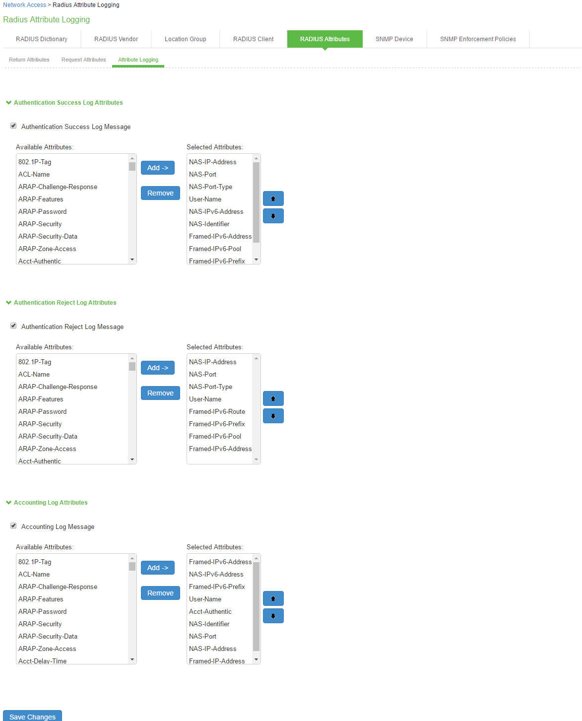
- Select Authentication Success Log Message and Authentication Reject Log Message.
- Select the Accounting Log Message option to specify the accounting log messages.
- Select Available attributes from the lists, and click Add to populate the Selected Attributes lists.
- Click Save Changes.
- To include the RADIUS accounting messages in user access logs, select System > Log/Monitoring > User Access > Settings and enable RADIUS Accounting Messages.
- The order of RADIUS attributes in the user access log is based on the order you select the attributes from the RADIUS attributes logging page.
Verifying the RADIUS Request Attribute Policy Configuration
When a user authentication fails because it did not meet the requirements specified in the RADIUS request attribute policy, a user event log message is displayed that includes information about which policies the user met or failed.
To display the User Access log:
- Select System Log/Monitoring.
- Click the User Access tab.
- Click the Log tab.
Verifying the RADIUS Dictionary
IPS supports many specific network access devices (NAD) by using its built-in standard RADIUS and vendor-specific, proprietary dictionary files. You can upload new dictionaries to add new RADIUS clients. IPS uses the dictionary files to store lists of RADIUS attributes, parse authentication requests, and generate responses.
To upload a new RADIUS dictionary:
- Select Endpoint Policy > Network Access > RADIUS Dictionary to display the preconfigured dictionaries and their associated vendors.
- Click New RADIUS dictionary.
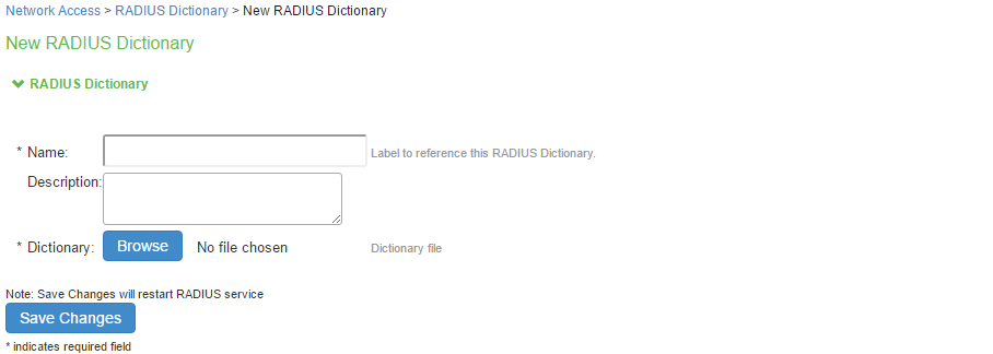
- Enter a Name and optionally a description for the new dictionary.
- Click Browse to search for the dictionary file (.dct) on a local or connected drive, then click Save Changes. The uploaded dictionary is displayed on the main RADIUS Dictionary page, and in the Make/Model list on the RADIUS Client page.
- Click Save Changes.
- You can only remove dictionaries that are not associated with a vendor.
- You can download any dictionary from the list, including preinstalled dictionaries. You can modify the downloaded dictionary and then upload it as a new make/model.
Verifying RADIUS Vendor List
RADIUS server contains a file with the list of manufacturers for the access devices, which communicate with the RADIUS server.
To verify the vendor and the associated dictionary on the RADIUS Vendor page:
- Select Network Access > RADIUS Vendor.
- Click New RADIUS Vendor, enter the name and then select the imported dictionary.
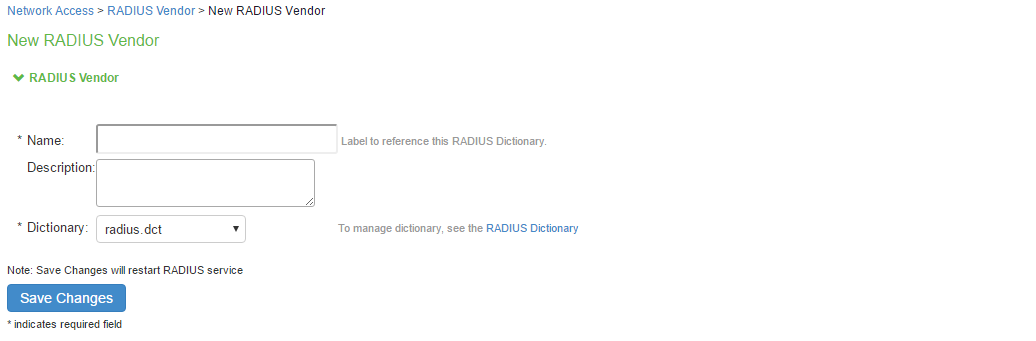
- Click Save Changes.
Additional Configurations
Configuration Commands for Cisco Switch
The below example shows a sample configuration of 802.1X authentication on Cisco switch. Only sample commands are documented in this example. For more information, see Cisco documentation.
The configuration involves the following:
- Configuring IPS server as a RADIUS server in configuration mode.
- Configuring 802.1X on the switch port in configuration mode.
Configuring IPS server as a RADIUS server
The sample configuration below shows how to add IPS server as a RADIUS authentication and accounting server on Cisco switch.
You must execute the following commands in the CLI configuration mode.
--Execute this command to add IPS as a RADIUS server
radius server <RADIUS SERVER NAME>
*Note* IPS listens to both 1812/1813 and 1645/1646 ports. Default is 1645 and 1646.
address ipv4 <RADIUS SERVER IP> auth-port 1645 acct-port 1646
key <SHARED-KEY>
--Execute these commands to create a RADIUS Server Group, and associate your IPS appliances to the group.
aaa group server radius <RADIUS-GROUP>
server name <RADIUS SERVER NAME>
*Note* Repeat for every IPS Appliance.
--Execute these commands to turn on AAA
aaa new-model
aaa session-id common
aaa authentication dot1x default group <RADIUS-GROUP>
aaa authorization network default group <RADIUS-GROUP>
aaa authorization auth-proxy default group <RADIUS-GROUP>
aaa accounting send stop-record authentication failure
aaa accounting identity default start-stop broadcast group <RADIUS-GROUP>
aaa accounting update newinfo
-- Execute this command to configure RADIUS CoA
aaa server radius dynamic-author
client <RADIUS SERVER IP> server-key <SHARED-KEY>
auth-type all
ignore session-key
port 3799
*Note* Default is 1700
--Optional commands for DHCP snooping and IP device tracking for dACL or filter id attributes
ip device tracking
ip dhcp snooping
ip http server
ip http secure-server
Configuring 802.1x and MAC Authentication
The below example shows a sample configuration of 802.1X and MAC Address authentication on Cisco switch interface. You must execute the following commands in CLI configuration mode.
interface GigabitEthernet1/0/24
switchport access vlan 60
switchport mode access
--Execute this command to trigger re-authentication from IPS
authentication periodic
authentication timer reauthenticate server
--Execute this command for configuring 802.1X access-session port-control auto
dot1x pae authenticator
--Execute this command for configuring MAC BYPASS
mab
spanning-tree portfast
service-policy type control subscriber POLICY_Gi1/0/24
--POLICY_Gi1/0/24 is a policy map configuration. See the POLICY_MAP configuration for more details.
--Specify the order of execution
authentication order mab dot1x
authentication priority dot1x mab
--Execute this command for viewing the status of the session on Cisco OS version 15.x and above
Show access-session interface gi-X/Y/Z detail
--Execute this command for viewing the status of the session on Cisco OS version 12.
Show authentication session interface gi-X/Y/Z detail
POLICY_MAP configuration
--Execute this command to define POLICY_MAP configuration
--Define class-map Policies
class-map type control subscriber match-all DOT1X
match method dot1x
!
class-map type control subscriber match-all DOT1X_FAILED
match method dot1x
match result-type method dot1x authoritative
!
class-map type control subscriber match-all DOT1X_MEDIUM_PRIO
match authorizing-method-priority gt 20
!
class-map type control subscriber match-all DOT1X_NO_RESP
match method dot1x
match result-type method dot1x agent-not-found
!
class-map type control subscriber match-all DOT1X_TIMEOUT
match method dot1x
match result-type method dot1x method-timeout
!
class-map type control subscriber match-all MAB
match method mab
!
class-map type control subscriber match-all MAB_FAILED
match method mab
match result-type method mab authoritative
--Define policy-map using class-map
sh run | beg POLICY_Gi1/0/24
policy-map type control subscriber POLICY_Gi1/0/24
event session-started match-all
10 class always do-until-failure
10 authenticate using mab priority 10
event authentication-failure match-first
5 class DOT1X_FAILED do-until-failure
10 terminate dot1x
20 authentication-restart 60
10 class MAB_FAILED do-until-failure
10 terminate mab
20 authenticate using dot1x priority 20
20 class DOT1X_NO_RESP do-until-failure
10 terminate dot1x
20 authentication-restart 60
40 class always do-until-failure
10 terminate mab
20 terminate dot1x
30 authentication-restart 60
event agent-found match-all
10 class DOT1X_MEDIUM_PRIO do-until-failure
10 authenticate using dot1x priority 20
event authentication-success match-all
10 class always do-until-failure
10 activate service-template DEFAULT_LINKSEC_POLICY_SHOULD_SECURE
Configuration Commands: EX Switch
set system services web-management http
set system services web-management https system-generated-certificate
--Execute this command for Employee dot1x
set protocols dot1x authenticator interface ge-0/0/31.0
protocols dot1x authenticator interface ge-0/0/32.0
--Agentless/Guest access
set protocols dot1x authenticator interface ge-0/0/35.0 mac-radius restrict
set firewall family ethernet-switching filter PERMIT-ALL.in term ALLOW_ALL from destination-address 0.0.0.0/0
set firewall family ethernet-switching filter PERMIT-ALL.in term ALLOW_ALL then accept
set access radius-server 10.96.69.26 dynamic-request-port 3799
set access radius-server 10.96.69.26 secret "$9$TQ6ABIcevLEcK8XxdVqmPQ69"
set access radius-server 10.96.69.26 source-address 10.96.4.43
set access profile juniper-access-profile authentication-order radius
set access profile juniper-access-profile radius authentication-server 10.96.69.26
set access profile juniper-access-profile radius accounting-server 10.96.69.26
set access profile juniper-access-profile accounting order radius
Configuration Commands: Huawei Switch
The below example shows a sample configuration of 802.1X authentication on Huawei switch (S5720). Only sample commands are documented in this example. For more information, see Huawei documentation.
# Creation of VLAN
vlan batch 100 200
# Creation of dot1x profile
dot1x-access-profile name <dot1x-profile-name>
authentication trigger-condition dhcp
# Creation of authentication profile mapped to dot1x-access-profile
authentication-profile name <auth-profile-name>
dot1x-access-profile <dot1x-profile-name>
authentication mode multi-authen max-user 100
# For MAC auth (MAB), enable below 2 commands
mac-access-profile <Mac-profile-name>
authentication dot1x-mac-bypass
# Domain in which authentication happens
domain isp
# When Switch acts as CoA server, decoding of calling-station-id format has to be specified.
radius-server authorization calling-station-id decode-mac-format ascii hyphen-split common
# Create IPS as radius-server, which will be mapped in aaa profile. Enter the same shared key as configured in IPS.
radius-server template rd-server-IPS
radius-server shared-key cipher %^%#~SZ#Wvmi~*}.Q`L'"|s;q9ci)(u&U4'!>:1Ja]T(%^%#
radius-server authentication <Radius-Server-IP> <1812> weight 80
radius-server accounting <Radius-Server-IP> <1813> weight 80
calling-station-id mac-format hyphen-split mode2 uppercase
# Configure the switch to support dynamic authorisation
radius-server authorization 192.168.10.11 shared-key cipher %^%#qIj!'3LZN1TkF=JkGF:Gx:U$:!c]HES=$BG.*HwY%^%#
# Configure aaa profile
aaa
authentication-scheme <auth-scheme>
authentication-mode radius
authorization-scheme default
accounting-scheme <accounting>
accounting-mode radius
accounting realtime 15
domain isp
authentication-scheme <auth-scheme>
accounting-scheme <accounting>
radius-server <rad-server-IPS>
# Create VLAN interfaces which will be used for enforcement
# Endpoint will get IP address in the VLAN to which it is assigned.
interface Vlanif100
ip address 192.168.10.10 255.255.255.0
dhcp select interface
interface Vlanif200
ip address 192.168.20.10 255.255.255.0
dhcp select interface
# Access Interface having authentication-profile as dot1x
interface GigabitEthernet0/0/17
description "EP Interface"
port link-type hybrid
Port hybrid untagged vlan 100 200
authentication-profile <auth-profile-name>
# Interface Connected to IPS server
interface GigabitEthernet0/0/19
description "connected to IPS"
port link-type access
port default vlan 100
Configuration Commands: Juniper EX Series Switch
The below example shows a sample configuration of 802.1X authentication on Juniper EX switch.
The configuration involves the following:
- Configuring IPS server as a RADIUS server in edit mode.
- Configuring 802.1x on the switch port in edit mode.
Configuring IPS server as a RADIUS server
The sample configuration below shows how to add IPS server as a RADIUS authentication and accounting server on Juniper EX switch. You must execute the following commands in edit mode.
set access radius-server <RADIUS SERVER IP> secret <SHARED-KEY>
set access radius-server <RADIUS SERVER IP> source-address 10.204.88.30
--Execute this command for configuring RADIUS CoA
set access radius-server <RADIUS SERVER IP> dynamic-request-port 3799
--Execute this command to add IPS as a RADIUS server
set access profile 802.1X-access-profile authentication-order radius
set access profile 802.1X-access-profile accounting order radius
set access profile 802.1X-access-profile radius authentication-server <RADIUS SERVER IP>
set access profile 802.1X-access-profile radius accounting-server <RADIUS SERVER IP>
Configuring 802.1x on the Switch Port
The below example shows a sample configuration of 802.1X / MAC address authentication on Juniper EX switch interface. You must execute the following commands in edit mode.
--Execute this command for 802.1X
set protocols dot1x authenticator authentication-profile-name 802.1X-access-profile
set protocols dot1x authenticator interface ge-0/0/0.0 supplicant multiple
--Execute this command for configuring MAC BYPASS
set protocols dot1x authenticator interface ge-0/0/0.0 mac-radius
--Execute this command for viewing the status of the session
Show dot1x interface ge-X/Y/Z detail
RADIUS Dictionary Files
This section contains dictionary translations for parsing requests and generating responses. All transactions are composed of Attribute/Value Pairs. The value of each attribute is specified as one of these valid data types shown in table.
|
Data |
Description |
|---|---|
|
hexadecimal |
Hexadecimal string |
|
hex1, hex4 |
1- or 4-byte hexadecimal number |
|
string |
0-254 octets (includes null terminator) |
|
stringnz |
0-254 octets (without null terminator) |
|
ipv6addr |
16 octets in network byte order (per RFC-3162) |
|
ipv6prefix |
2-18 octets in network byte order (per RFC-3162) |
|
ipv6interface |
8 octets in network byte order (per RFC-3162) |
|
ipaddr |
4 octets in network byte order |
|
ipaddr-pool |
IP address selected from an IP address pool |
|
ipxaddr-pool |
IPX network number selected from an IPX address pool |
|
integer |
32-bit value in big endian order (high byte first) |
|
int1, int4 |
1- or 4-byte decimal number (integer is equivalent to int4) |
|
time |
32-bit value in big endian order; seconds since 00:00:00 GMT, Jan. 1, 1970 |
All attribute names and value names in the supplied radius.dct dictionary are derived from the RADIUS specification by replacing all nonalphanumeric characters with dashes (-).
The following dictionary format provides a mechanism for including secondary dictionaries from the text of a primary dictionary. For example, only the attribute/value definitions that differ from the RADIUS specification need to be listed in a primary dictionary for a vendor specific implementation. Definitions for the attribute/values that are common to both are brought in by including the radius.dct dictionary anywhere within the vendor dictionary.
The following rules apply to the creation and use of dictionaries:
- All comments begin with a pound sign (#) in column 0 OR appear on an attribute or value line with <white space>#<white space> as the Mandatory delimiter between dictionary data and comment text. (This is a simple parser.)
- Include another dictionary file with an at sign (@). The (@) character must be in column 0.
- All attribute and attribute value names and numeric codes must be unique within a single dictionary. Conflicts between dictionaries are resolved according to the following rules:
- Attributes and values have precedence over any that are parsed later, and parsing is depth first.
- For example, to override a baseline attribute, create a file with that attribute in it, followed by an include of the baseline file. Because the baseline file is parsed later than the desired override, the baseline file is ignored.
- When two secondary dictionary definitions of an attribute or value conflict, the earlier include takes precedence.
- Other than include files, there are two meaningful line entry formats in a dictionary -one for attributes and one for attribute values.
- ATTRIBUTE_KEY ATTRIBUTE_NAME ATTRIBUTE_CODE DATA_TYPE FLAGS [COMMENT_DELIMITER COMMENT_TEXT]
- VALUE_KEY ATTRIBUTE_NAME VALUE_NAME VALUE_CODE [COMMENT_DELIMITER COMMENT_TEXT]
- The legend for the last column of an attribute entry should be:
- 'c' indicates a SINGLE value attribute that is a candidate for inclusion in a user's checklist.
- 'C' indicates a MULTI value attribute that is a candidate for inclusion in a user's checklist.
- 'r' indicates a SINGLE value attribute that is a candidate for inclusion in a user's reply list.
- 'R' indicates a MULTI valued attribute that is a candidate for inclusion in a user's reply list.
- 'o','O' ordered attribute, some attributes (such as Reply-Message) might need to be presented in a particular order to make sense.
- The absence of {C,c,R,r} flags indicates an item that is neither a reply nor a check list item (such as State, Proxy-State).
- All FLAG characters on a given attribute line must be clustered together to parse properly. No white space is allowed between individual characters.