System Overview
Introduction
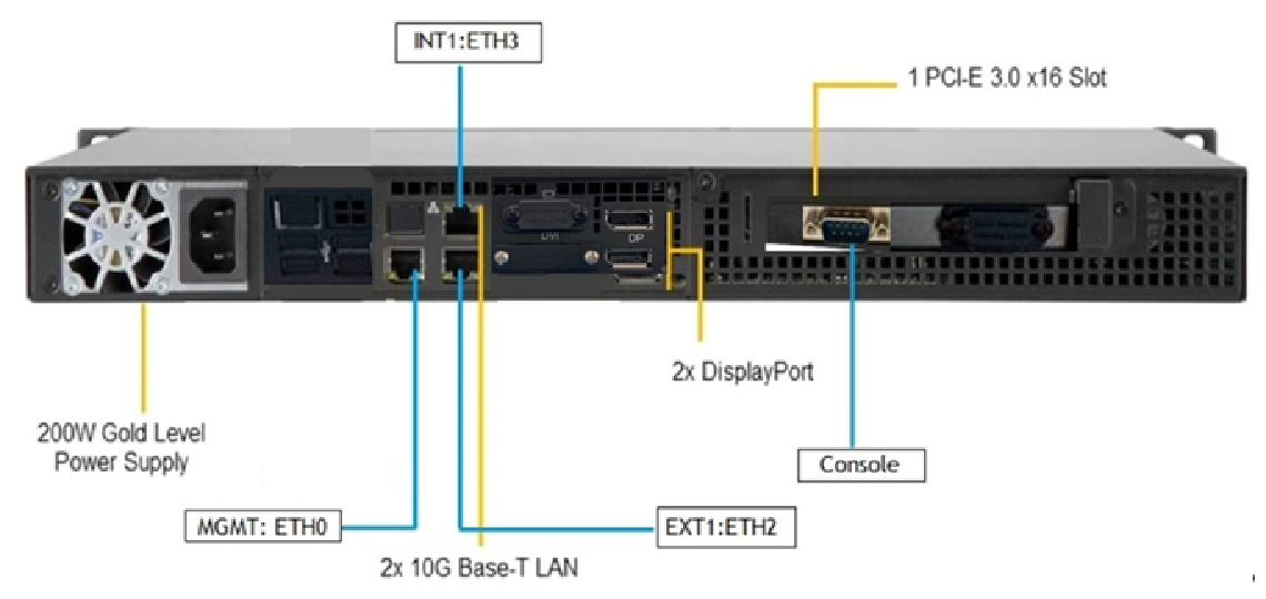
The ISA6000 features a unique and highly optimized design for low wattage processor platforms. It is equipped with a high-efficiency low noise power supply. High-performance fans provide ample optimized cooling.
For added system security, the USB ports have been disabled.
LED Control Panel
The control panel located on the front of the ISA6000 chassis includes power control buttons and status LEDs. This section describes the LED indicators and the appropriate responses.
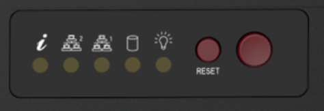
Control Panel Buttons
The control panel includes a power on/off button and a reset button.

Power: The main power switch is used to apply or remove power from the power supply to the server system. Turning off system power with this button removes the main power but keeps standby power supplied to the system. Therefore, you must unplug system before servicing.

Reset: The reset button is used to reboot the system.
Control Panel LEDs
The control panel displays five LEDs to monitor the system.

Information LED: Alerts operator of several states, as noted in the table below:
|
Status |
Description |
|---|---|
|
Continuously on and red |
An overheat condition has occurred. This may be caused by cable congestion. |
|
Blinking red (1Hz) |
Fan failure; check for an inoperative fan. |
|
Blinking red (0.25Hz) |
Power failure; check for a non-operational power supply. |

NIC1 (GLAN1): Associated with the Management port. It indicates network activity when flashing.

NIC2 (GLAN2): Unused. Will always be off.

HDD: Indicates SATA drive activity when flashing.
-
Continuously ON: indicates continuous read/write operation on HDD.
-
Blinking: indicates Less activity on HDD.

Power: Indicates power is being supplied to the system power supply. This LED should be illuminated when the system is operating.
Management Port LEDs
The management port has two LEDs. The yellow LED indicates activity, while the link LED may be green, amber, or off to indicate the speed of the connection.
|
LED |
Color |
Description |
|---|---|---|
|
Activity |
Yellow (flashing) |
Active |
|
Link |
Off |
No connection |
|
|
Orange |
1 Gbps speed |
|
|
Green |
100 Mbps speed |
INT and EXT Port LEDs
Two LAN ports are located on the NIC card. Each Ethernet port has two LEDs.
|
LED |
Color |
Description |
|---|---|---|
|
Activity |
Yellow (blinking) |
LAN Active |
|
Link |
Off |
10 Mbps link speed or no connection |
|
|
Orange |
1 Gbps link speed |
|
|
Green |
10 Gbps link speed |
Air Flow Estimate
|
Equipped Cooling Fan and/or Active CPU Heat Sink |
Estimated Overall System Air Flow Rate When All Four Cooling Fans Operated at Full Speed |
|---|---|
|
4x Cooling FAN + 1 passive CPU Heat Sink |
29 CFM |
Air Flow Direction
The following table gives the air flow direction of the power supply fan and internal CPU fan.
|
Component |
Air Flow Direction |
|---|---|
|
Power Supply Fan |
To the rear of the unit |
|
Internal CPU Fan |
To the rear of the unit |
Beeping and Alarms
|
Beep Code |
Description |
|---|---|
|
5 short beeps + 1 long beep every 5 seconds |
No memory detected in the system |
|
Continuous beep (“i” LED on front panel turns RED) |
System overheat condition |