Installation
This chapter provides instructions and tips for installing the chassis into a rack.
Preparing for Setup
Please read this section in its entirety before beginning the installation procedure.
Choosing a Setup Location
Decide on a suitable location for the rack. It should be a clean, dust-free area that is well ventilated. Avoid areas where heat, electrical noise and electromagnetic fields are generated. Place it near a grounded power outlet.
•Leave at least 25 inches clearance in front of the rack to open the front door completely.
•Leave approximately 30 inches of clearance in the back of the rack to allow for sufficient airflow and ease in servicing.
•Install in a restricted access location, such as a dedicated equipment room or service closet.
Ambient Operating Temperature
If installed in a closed or multi-unit rack assembly, the ambient operating temperature of the rack environment may be greater than the ambient temperature of the room. Install the equipment in an environment compatible with the manufacturer’s maximum rated ambient temperature (TMRA).
Adequate Airflow
Equipment should be mounted into a rack so that the amount of airflow required for safe operation is not compromised.
Circuit Overloading
Avoid overloading the power supply circuitry or any overcurrent protection equipment. Use equipment nameplate ratings to calculate your requirements.
Reliable Ground
A reliable ground must be maintained at all times. To ensure this, ground the rack, itself. Pay attention to power supply connections other than the direct connections to the branch circuit, such as power strips.
Physical Rack Precautions
•Ensure that the leveling jacks on the bottom of the rack are fully extended to the floor with the full weight of the rack resting on them.
•In single rack installation, stabilizers should be attached to the rack.
•In multiple rack installations, the racks should be coupled together.
•When mounting this unit in a partially filled rack, load the rack from the bottom to the top with the heaviest component at the bottom of the rack. If this is the only unit in the rack, mount it at the bottom.
•Always make sure the rack is stable before extending a component from the rack. Extend only one com- ponent at a time. Extending two or more simultaneously may cause the rack to become unstable.
Warning: Follow these guidelines to prevent injury. Take all precautions to ensure the system remains stable
General Server Precautions
•Review the electrical and general safety precautions that came with the components you are adding to your chassis.
•Determine the placement of each component in the rack.
•Install the heaviest server components on the bottom of the rack first, and then work up.
•Use a regulating, uninterruptible power supply (UPS) to protect the server from power surges, voltage spikes and to keep your system operating in case of a power failure.
•Allow the hard drives and power supply modules to cool before touching them.
•Always keep the rack front door, all panels and all components on the servers closed when not servicing, to maintain proper cooling.
Warning: If you unscrew and open the chassis cover, it will void your product warranty.
Rack Mounting Instructions
The chassis can be mounted in a rack for secure storage and use. To set up your rack, follow the step-by-step instructions included in this manual.
Rail packaging includes:
•One pair of inner slides to be installed on the chassis.
•One pair of outer slides to be installed in the rack.
•Two pairs of short brackets to be used on the front side of the outer slides.
One pair of short brackets include screw threads, and the other pair do not. Use the only pair that will fit into your rack.
•One pair of long brackets to be used on the rear side of the outer slides.
Installing Inner Slides
1.Locate the right inner slide, (-the slide that will be used on the right side of chassis when facing the front panel of the chassis).
2.Align the four(4) square holes on the right inner slide against the hooks on the right side of the chassis as shown in the illustration below.
3.Securely attach the slide to the chassis with two M4 flat head screws and repeat the steps 1-3 to install the left inner slide to the left side of the chassis.
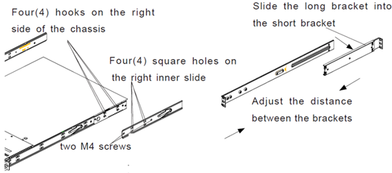
Installing Outer Slides
1.Measure the distance from the front rail of the rack to the rear rail of the rack.
2.Attach a short bracket to the rear side of the right outer slide, and a long bracket to the front side of the right outer slide as shown above on the right.
3.Adjust the short and long brackets to the proper distance so that the chassis can snugly fit into the rack.
4.Secure the slides to the cabinet with screws. Repeat steps 1-4 for the left outer slide.
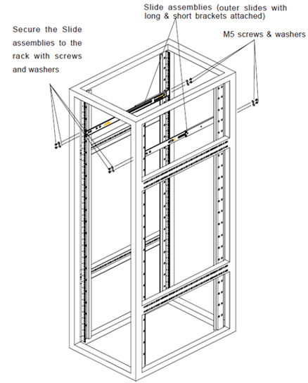
Installing the Slide Assemblies to the Rack
1.After you have installed the short and long brackets to the outer slides, you are ready to install the whole slide assemblies (outer slides with short and long brackets attached) to the rack. (See the previous page.)
2.Use M5 screws and washers to secure the slide assemblies into the rack as shown in the illustration below.
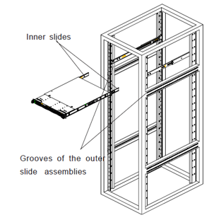
Installing the Chassis into the Rack
1.Push the inner slides, which are attached to the chassis, into the grooves of the outer slide assemblies that are installed in the rack as shown in the illustration below:
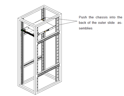
2.Push the chassis all the way to the back of the outer slide assemblies as shown in the illustration below. (The plastic bezel is not included in the package.)
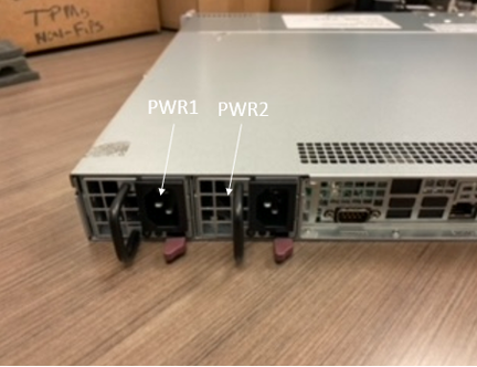
Replacing the Power Supply Unit
The ISA8000 chassis has two 400W power supplies. This power supply is auto-switching capable. This enables it to automatically sense and operate at a 100V to 240V input voltage. An amber light will be illuminated on the power supply when the power is off. An illuminated green light indicates that the power supply is operating.
The ISA8000 chassis includes a redundant power supply. It is not necessary to power down the server to replace a power supply. PWR1 and PWR2 are shown in the graphic below:
To replace the power supply:
1.Push the Release tab (on the back of the power supply) as illustrated.
2.Pull the power supply out using the handle provided.
3.Replace the failed power module with a new unit. To do this, push the new power supply module into the power bay until you hear a click.
4.Plug the AC power cord back into the module.
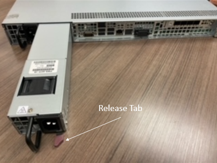
Warning: Removal of two power supply units at the same time is not recommended.
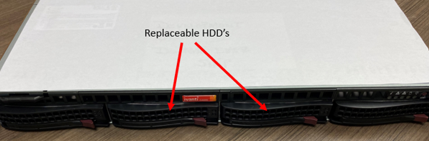
Replacing the Hard Drive
The ISA8000 chassis has two replaceable hard disk drives located in slot #2 and slot #3.
Note: The SSD drive in slot 1 is not replaceable and should never be removed.
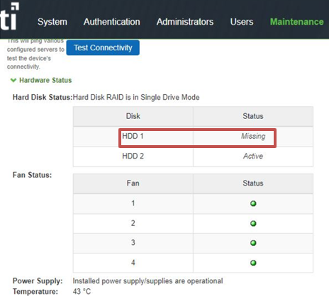
You can check the HDD and RAID status from the Maintenance page of ICS Gateway Admin UI. If the status of HDD1 or HDD2 displays “Missing” or “Faulty”, then that specific HDD needs to be replaced. If any one of the two HDDs has gone bad, then the RAID will not function.
From 22.1R4 release, hot swapping of hard drive is supported. When you are replacing the hard drive during Maintenance period, and shutting down the server does not affect your network, follow the cold swap procedure. Otherwise, follow the hot swap procedure.
Replacing Faulty Hard drive (Cold Swap)
To replace a hard drive (cold swap):
1.Power off the system.
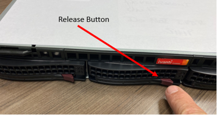
2.Push the Release button of the faulty hard drive to release the ejector lever.
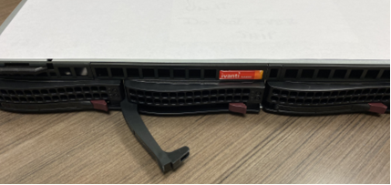
3.Pull the Release lever on the drive that needs to be replaced as shown below.
4.Pull the hard drive out using the lever provided. This will disengage the HDD connector from the HDD controller backplane.
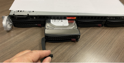
5.Replace the failed hard drive with a new unit. To do this, push the new hard drive into the HDD bay and snap the lever shut.
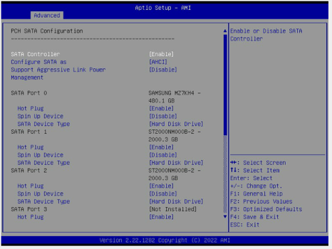
6.Power on the system and continuously press the Del button to enter the BIOS settings.
7.Select Advanced > PCH SATA Configuration.
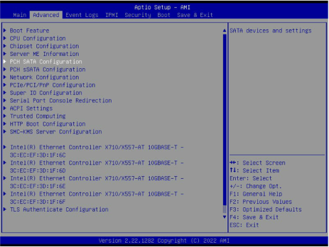
8.Check for the status of the newly inserted HDD.
9.Once the new HDD is detected, reboot the system.
10.When system boots up properly, check for the HDD and RAID status.
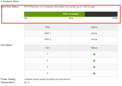
11.Log in to the ICS Gateway Admin UI and select the Maintenance tab. The message “RAID Recovery in progress” will be displayed.
12.The process will take 30-45 mins.
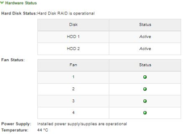
13.Once the process is completed, HDD and RAID display the status “HDD Active” and “Hard Disk Raid is Operational”.
Warning: Once RAID is in the Active state, only one HDD replacement is allowed.
Replacing Faulty Hard drive (Hot Swap)
To replace a hard drive (hotswap):
1.Telnet to the admin console.
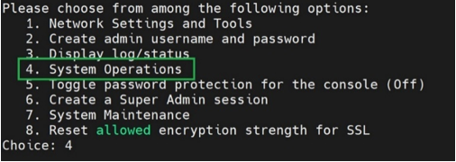
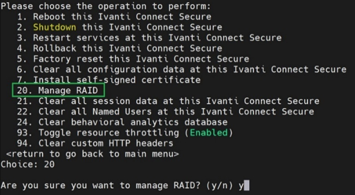
2.Select option 4. System Operations from the CLI menu.
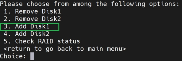
3.Then select option 20. Manage RAID that provides RAID management menu options.
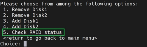
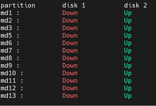
4.Select option 5. Check RAID status.
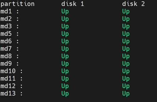
5.When both the disks are active and working, the status shows Up.
6.Return to the RAID management menu, and select the faulty disk that you want to remove, for example, option 1. Remove Disk1.
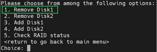
7.Select option 5. Check RAID status. The status of disk1 shows Down.
Now you can physically replace faulty disk1 with new working disk.
8.Identify the slot where faulty disk1 is located. Push the Release button to release the ejector lever.
9.Pull the Release lever of faulty disk1 as shown below.
10.Pull the hard drive out using the lever provided. This will disengage the HDD connector from the HDD controller backplane.
11.Replace the faulty disk1 with a new unit. To do this, push the new hard drive into the HDD bay and snap the lever shut.
12.In the RAID management menu, select 3. Add Disk1.
13.Log in to the ICS Gateway Admin UI and select the Maintenance tab. The message “RAID Recovery in progress” will be displayed.
14.The process will take 30-45 mins.
15.Once the process is completed, HDD and RAID display the status “HDD Active” and “Hard Disk Raid is Operational”.
Warning: Once RAID is in the Active state, only one HDD replacement is allowed.
Network Cables
The ISA8000f model offers SFP+ interfaces supporting 10G fiber networks.
ISA8000f
This appliance offers dual and redundant 10G network interface ports (4 ports total) in the SFP+ form factor. Ivanti has qualified SFP+/Cable combinations (Short Range, 850 nm) and offers them for sale as an optional accessory. Check the Price book for the SKUs.
Customers can either purchase this option from Ivanti or procure it from their vendor of choice. Contact your Solutions Engineer or Technical Support for additional information and Technical Specifications.
The performance tests done with Finisar (Juniper) transceiver on the cable end that is connected to the Juniper switch, and Avago transceiver on the cable end that is connected to the ISA8000 show no impact on the throughput using longer cables. The maximum cable length qualified is 15 meters.
Support for 1G Network:
• The Network interface card in the ISA8000f is designed for 10G networks, but it can support 1G networks when used with 1G transceivers at both ends of the network. No manual set up is required. Ivanti does not offer any optional 1G transceiver / cable as an option for sale. Any supplier’s short range 1G transceiver should work.
The ISA8000f model offers SFP+ interfaces supporting 10G fiber networks.
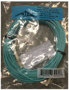
10G fiber solution supports either an Avago SFP+ direct attached 3 meters transceiver cable (ISA-SFP-10GE-SR-3M), the Avago SFP+ detached transceiver with 5 meters fiber cable (ISA-SFP-10GE-SR-DE), or any of the SFP+ fiber transceivers listed below using from 5 meters to 25 meters cable.
Listed below are the supported detached 10Gb/s SFP+ fiber transceivers:
• Avago AFBR-709DMZ
• Cisco SFP-10G-SR-S Module (S-Class)
• Cisco SFP-10G-SR Module
• Juniper EX-SFP-10GE-SR
• HP X132 10G SFP+ LC SR
ISA8000c
This appliance offers dual and redundant 10G network interface ports (4 ports total) in the RJ45 form factor compatible with category 6 or 6A network cables.
The hardware supports auto-negotiation between 1G and 10G networks over an RJ45 connection. Ivanti does not offer any RJ45 cables/accessories as an optional SKU.