Traffic IP Addresses and Traffic IP Groups
In a typical network, your back-end servers will be arranged in a local network, with local IP addresses, and will not directly contactable from the Internet. The front-end Traffic Manager machines will have externally available IP addresses, and will be able to connect to the back-end machines over the local network.
The front-end machines will have permanent IP addresses on each network, with the front-end addresses visible and routable from the Internet. These IP addresses are configured by the OS, and if the machine fails, the IP address is lost.
For this reason, these permanent IP addresses are not suitable to use when you publish your services. In the event of a hardware or system failure, your services would become partially or wholly unavailable.
The Traffic Manager’s fault tolerance capability allows you to configure Traffic IP addresses. These IP addresses are not tied to individual machines, and the Traffic Manager cluster ensures that each IP address is fully available, even if some of the clustered Traffic Manager machines have failed.
In a typical fault-tolerant configuration, the DNS name used to publish your services is configured to resolve to the traffic IP addresses in your Traffic Manager cluster. This ensures that your services are always fully available.
The traffic IP addresses are arranged into a Traffic IP group. This group spans some or all of your Traffic Manager machines. The machines negotiate between them to share out the traffic IP addresses, each Traffic Manager then raises the IP address (or IP addresses) allocated to it.
Setting up traffic IP groups is described in Traffic IP Groups and Fault Tolerance.
If any Traffic Manager machine should fail, the other Traffic Managers in the group detect this. One of them then takes over the failed machine’s traffic IP addresses to ensure that the service is uninterrupted.
By default, fault tolerance uses unicast traffic to distribute health information and to manage traffic to multi-hosted Traffic IP Addresses. If you change your configuration to use multicast traffic, the switches that your Traffic Managers are connected to must support IGMP snooping, and messages broadcast to the multicast address used by your Traffic Managers should be forwarded to all Traffic Managers in the cluster.
When you join a Traffic Manager to an existing cluster, a number of tests are conducted automatically to ascertain whether broadcast messages are correctly forwarded.
Traffic IP Address Modes
The Traffic Manager supports several modes:
•Single-hosted: Traffic IP addresses are raised on a single Traffic Manager in your fault tolerant cluster. If that Traffic Manager fails, another Traffic Manager will raise that IP address and start accepting traffic.
•Multi-hosted: Traffic IP addresses are raised on all of the Traffic Managers in your cluster, using a multicast MAC address that ensures that all incoming traffic is sent to all machines. A custom Linux kernel module is used to evenly distribute the traffic between the working Traffic Managers.
•Route Health Injection: Traffic IP addresses are raised "privately" (on loopback) by all participating Traffic Managers, and dynamically advertised into the adjacent routing domain, using either Open Shortest Path First, version 2, (OSPFv2) or Border Gateway Protocol (BGP) as the routing protocol. In response, routers direct traffic to the active Traffic Manager. See Route Health Injection and the Network.
Enabling Multi-Hosted Traffic IP addresses imposes a performance hit due to the additional packet processing required by the Traffic Managers in your cluster. Empirical tests indicate that CPU utilization will increase by 25-30% at moderate traffic levels (10,000 requests per second), with a corresponding limit on top-end capacity.
Multi-hosted IP functionality is available on all versions of the Traffic Manager hardware appliance and virtual appliance. It is not included by default with the Traffic Manager software variant; however, you can download and install it as an additional kernel module. It is supported on Linux kernels, version 2.6.18 and later. For further information regarding supported versions, see the Pulse Community Web site at https://community.pulsesecure.net.
Example Configurations
These configurations assume that you have two Traffic Managers in your cluster, but can be extended if your cluster contains three or more Traffic Managers.
Active-Passive Configuration – Single-Hosted and Route Health Injection Modes
Suppose your Web site’s external DNS name maps to the IP address 162.34.64.29. You have two Traffic Manager machines handling traffic for a number of back-end Web servers:
•With single-hosted mode, you can set up a single-hosted traffic IP group spanning both Traffic Manager machines, containing this single IP address. The Traffic Managers will negotiate and one of them will raise the IP address. It handles all the incoming requests. The second Traffic Manager machine is available on standby. If the first machine should fail, the second machine takes over the IP address and starts to manage the traffic.
•With Route Health Injection (RHI) mode, you can set up an RHI traffic IP group spanning both Traffic Managers, containing the single IP address. Set one Traffic Manager as active and the other as passive. Both Traffic Managers advertise the IP address, using an OSPFv2 and/or BGP (depending on your choice of routing protocol) metric to express preference (the active Traffic Manager uses a lower metric). The upstream router (typically your default gateway) chooses the lowest metric route, sending all traffic to the active Traffic Manager. If the Traffic Manager detects a failure, it cancels the advertisement. If the router detects a failure, it disregards that route. In either case, the router switches to sending traffic according to the next-best metric advertisement, which in this case is the passive Traffic Manager.
The advantage of this configuration is that you can be confident that there is sufficient resource in reserve to handle the traffic should one of the two Traffic Managers fail. Debugging and fault resolution is easier when only one Traffic Manager is handling traffic.
Active-Active Configuration – Single and Multi-Hosted Modes
In an active-active configuration, both Traffic Managers manage your traffic. The distribution mode (single-hosted IP or multi-hosted IP) controls how the traffic is shared between them.
With single-hosted mode, you can configure two traffic IP addresses in a traffic IP group, and configure your DNS name to map to the two addresses, such as 162.34.64.29 and 162.34.64.30. The Traffic Managers will negotiate to raise one traffic IP address each. A DNS server can allocate requests to each IP address in turn (round-robin DNS), and each Traffic Manager handles the requests it receives.
If one of the machines fails, the other machine will detect this. It will then raise the failed machine’s traffic IP address in addition to its own, and handle all the traffic sent to either address.
With multi-hosted mode, you can continue to operate with one traffic IP address, simplifying your DNS and reducing the number of externally facing IP addresses you require. The traffic IP address is raised on all of the Traffic Managers in the traffic IP group, and incoming traffic to that IP address is shared evenly between the Traffic Managers.
Active-Active with Loopback (Single External Address, Single Hosted Mode)
If multi-hosted mode is not available or prohibited in your infrastructure, you can distribute traffic load to all of the Traffic Managers in your cluster, while still using a single external traffic IP address.
This configuration involves an additional "loopback" virtual server that listens for traffic on the external traffic IP address and then load-balances the requests across the Traffic Managers using their permanent IP addresses.
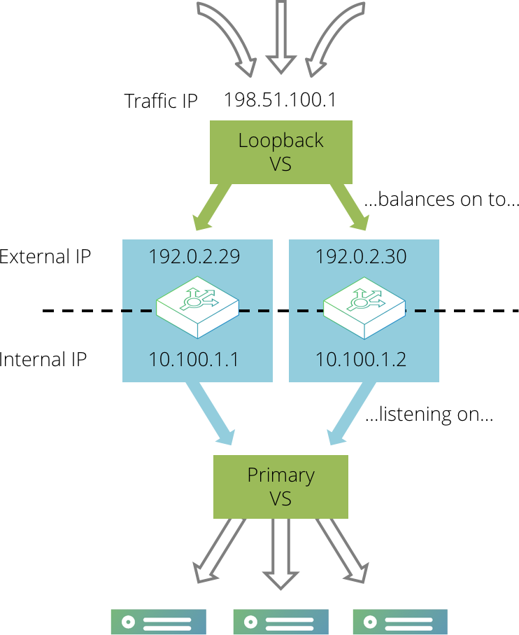
First, create your primary virtual server that processes traffic and load-balances it across the back-end servers. Configure this virtual server so that it listens on internal IP addresses and ports on each Traffic Manager, rather than externally accessible ones. For example, the virtual server could listen on 192.0.2.1:80 and 192.0.2.2:80, where the IP addresses are internally visible only.
Then, create a second “loopback” virtual server that listens on the single external IP address and immediately distributes traffic to the primary virtual server across the various Traffic Manager machines in your cluster.
As in the active-passive example, set up a single traffic IP address that will be raised by one Traffic Manager only. Any traffic coming in to this address should then be processed by the simple loopback virtual server, which is listening on that traffic IP address. The loopback virtual server should immediately select a loopback pool that contains the internal IP addresses of the Traffic Manager machines in the cluster; the loopback pool should use a either round-robin or least connections load balancing to evenly distribute traffic across the Traffic Manager machines in the cluster. It should not use a load-balancing method that is influenced by response time, as that will give very uneven request distribution.
The loopback virtual server uses little processing power. Ensure that all of the CPU-intensive processing is performed by the primary virtual server - tasks such as SSL decryption, rules, content compression, and so on.
This method splits the load of more intensive tasks between the two Traffic Managers. If either Traffic Manager fails, the service will continue to run (perhaps with a momentary interruption to some traffic). For example, if the Traffic Manager that is hosting the external traffic IP address were to fail, the traffic IP would be transferred to the remaining Traffic Manager. The loopback pool will detect that one of the nodes was unavailable and direct all traffic to the primary virtual server running on the remaining Traffic Manager.
The target virtual server will observe the connection originating from the loopback virtual server, not the remote client. Generally, the “X-Forwarded-For” or “X-Client-Cluster-Ip” headers can be used to determine the correct source for the connection, but in the common case where SSL requests are forwarded by the loopback virtual server, you should use the ssl_enhance and ssl_trust_magic settings described in the Preserving IP Addresses with SSL Forwarding section in SSL Encryption
Multiple-Redundant (N+M) Configuration
In the earlier cases, two Traffic Manager machines are used; if one should fail, a single point of failure is introduced into the system. When running mission-critical services, a higher level of protection can be employed by incorporating several additional Traffic Manager machines to form a multiple-redundant cluster.
Suppose that in normal operation you want to use N active Traffic Managers. You would then incorporate M passive Traffic Managers, where M is the number of machines that could potentially fail without reducing the number of Traffic Managers in operation.
To achieve this arrangement, you would need N+M front-end machines running the Traffic Manager. You can create a traffic IP group containing N traffic IP addresses, yet spanning all N+M machines. If a machine in your active group fails, a backup machine from the passive group is brought into active duty to take up the load. If another machine fails, an additional passive Traffic Manager becomes active, and so on. This is a typical clustering arrangement incorporating multiple layers of redundancy.
Using IP Transparency with a Cluster
Using IP transparency with a cluster of Traffic Manager machines introduces additional complexity because each server node is configured to route to a single Traffic Manager IP address. However, any of the Traffic Manager machines in the cluster may send transparent connections to the server nodes, and the nodes must route each response back via the Traffic Manager that originated the connection.
Active-Passive Configuration
With a single active Traffic Manager configuration, this can be achieved using the keeptogether setting in a traffic IP group that uses single-hosted IP addresses.
Create a traffic IP group containing two IP addresses; the front-end IP address for incoming traffic, and a back-end IP address that resides on the server side network. Select the keeptogether option in the traffic IP group.
Configure each back-end server to route all traffic via the back-end IP address you configured in the traffic IP group.
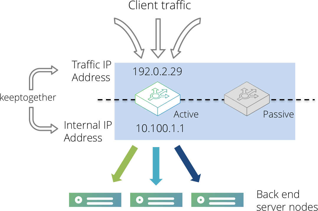
With this configuration, both IP addresses will be hosted on the same Traffic Manager machine. If that machine were to fail, both IP addresses would be migrated to the same passive machine, making it the new active machine. The back-end servers will now route traffic back via the new active machine.
Active-Active Configuration
With a configuration involving multiple active Traffic Managers, it is necessary to partition your back-end servers into groups, one for each active Traffic Manager machine. These groups should then be defined as pools within the Traffic Manager Admin UI, adding each back-end server as a node accordingly.
All servers in the same pool should have their default route configured to be the back-end IP address of the corresponding Traffic Manager. Please refer to your operating system documentation for more details about how to manipulate your server route settings.
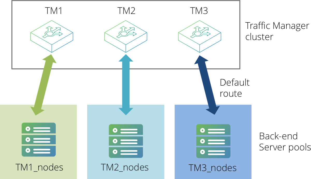
TrafficScript rules can then be used to select the correct pool to route traffic to, based on either of the following items:
•The name of the Traffic Manager that is managing that connection.
•The local client-side IP address (if using several "keeptogether" Traffic IP Groups in single-hosted mode).
The following code snippet demonstrates how this might work (using the Traffic Manager name as the selection criteria):
$hostname = sys.hostname();
if( $hostname == "TM1" ) {
pool.use( "TM1_nodes" );
}
if( $hostname == "TM2" ) {
pool.use( "TM2_nodes" );
}
if( $hostname == "TM3" ) {
pool.use( "TM3_nodes" );
}
This configuration does, however, include the limitation whereby if a Traffic Manager fails the associated pool will become redundant. Additionally, session persistence cannot reliably be used (particularly if multi-hosted IP addresses are in use).
IP transparency can be used selectively. For example, suppose that a Traffic Manager cluster is managing high volume Web traffic to www.mysite.com, and low volume SMTP traffic to mail.mysite.com. Only the SMTP traffic needs to be transparent. In this case, the following is true:
•www.mysite.com can resolve to several IP addresses in an Active-Active TrafficCluster configuration without IP transparency.
•mail.mysite.com can resolve to a single IP address using the Active-Passive keeptogether configuration described above.
Route Health Injection and the Network
When using Route Health Injection (RHI), the Traffic Manager communicates with routers in the adjacent routing domain. Once it has established communication, the Traffic Manager joins the routing domain and advertises RHI traffic IP addresses into it.
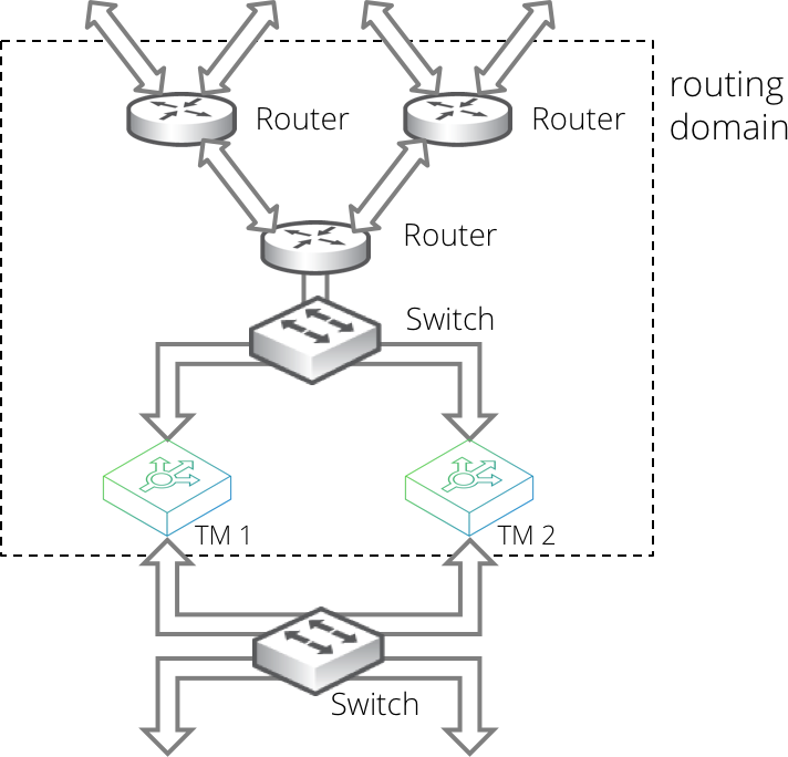
Such advertisements are dynamic and respond automatically to your Traffic Manager configuration changes that create, destroy, or move RHI traffic IP addresses. The advertisements also respond automatically to failures detected by the Traffic Manager, and through the routing domain's dynamic routing protocols, to network failures that are not local to the Traffic Manager.
RHI is therefore able to work in a wide variety of deployments. For example, on a small scale to manage simple local failover (such as within a single datacenter rack), and on a large scale to manage traffic distribution and failover between different datacenters within an enterprise or across the whole Internet.
RHI operates using RHI-designated IPv4 traffic IP groups. In a single location, you can use an RHI traffic IP group serviced by either a single active Traffic Manager, or an active-passive pair of Traffic Managers (See "Active-Passive Configuration – Single-Hosted and Route Health Injection Modes" on page 43).
RHI does not support Traffic IP groups based on IPv6 addresses.
To increase scale, you can repeat this pattern in further Traffic Manager datacenter locations as necessary. Different locations use different RHI traffic IP groups, where the Traffic IP addresses in each group are identical, but the OSPFv2 or BGP metrics used are typically different.
For OSPFv2, this scenario requires all datacenters to be in the same routing domain. For BGP, datacenters can be internal or external to the routing domain.
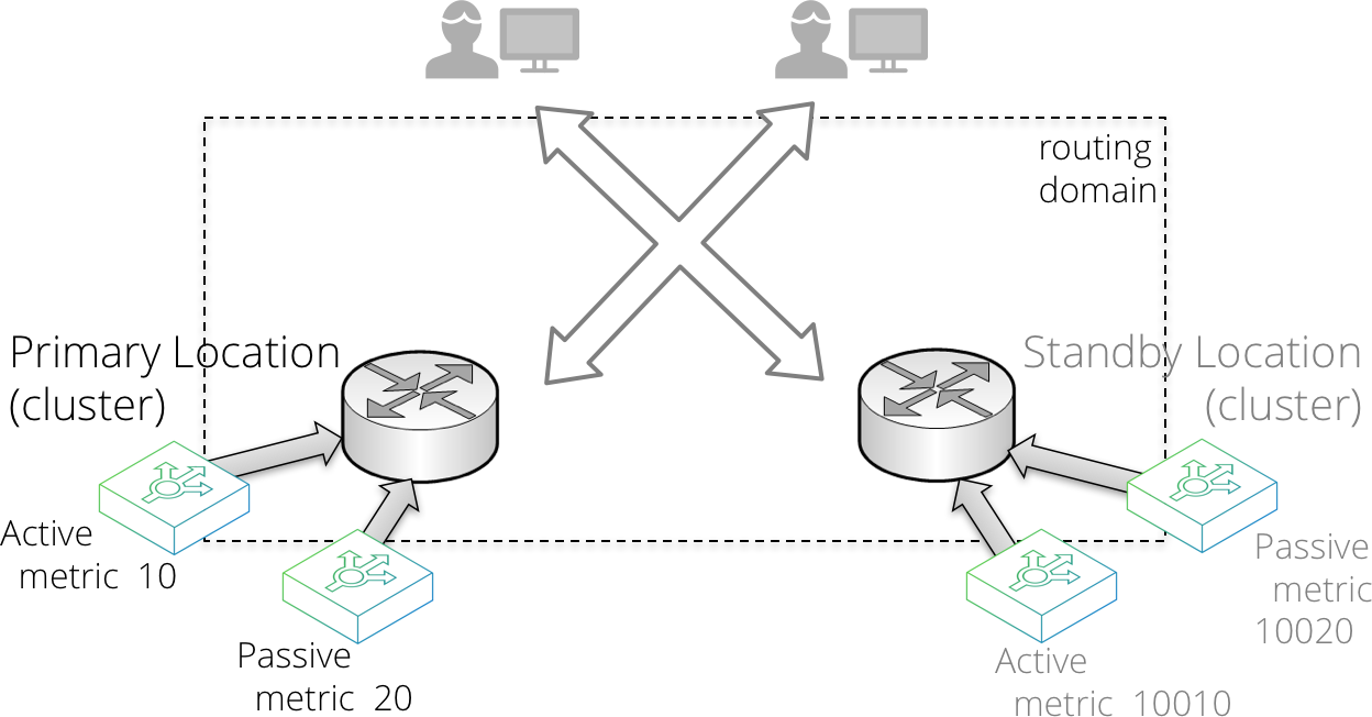
Locations might have different priorities. For example, with a two-location primary-standby datacenter deployment, you configure the following:
1.In the primary datacenter, configure a primary RHI traffic IP group serviced by an active-passive Traffic Manager pair.
2.In the standby datacenter, configure a standby RHI traffic IP group serviced by an active-passive Traffic Manager pair.
3.Configure the standby RHI traffic IP group with a very high metric, such that the primary datacenter is always preferred unless it is unavailable.
Alternatively, your datacenter locations might have similar priority, resulting in multiple active locations where routing decisions are based on using the best route, according to the network topology. This is often referred to as an anycast configuration. To achieve it, configure the RHI traffic IP groups in each location with the same metrics.
RHI implemented with BGP over multiple locations requires other parts of your infrastructure to be configured to support it. In other words, you must ensure that the routers between your datacenter locations respect the supplied metrics, and do not have other policies configured that might influence location choice.
The Credentials Used for RHI Communications
To implement RHI, each Traffic Manager communicates with adjacent routers using OSPFv2 or by establishing a session with BGP. You must configure your Traffic Manager with suitable credentials to enable the Traffic Manager to establish communications with an adjacent OSPFv2 or BGP enabled router. This process is called “peering” with the router.
OSPFv2 communication requires multicast.
You can create clusters of Traffic Managers that use the same credentials. Each cluster (or each Configuration Location within a Multi-Site Manager cluster; see "Multi-Site Cluster Management" on page 404) uses one set of credentials, and therefore all Traffic Managers in the cluster (or Configuration Location) join the same area (for OSPFv2) or Autonomous System (AS) (for BGP).
If you have multiple locations that require different credentials, the Traffic Managers in the different locations do not need to be clustered. If, however, you want to cluster them, you must use the Traffic Manager's Multi-Site Manager functionality.
To enter your OSPFv2 or BGP credentials, use the System > Fault Tolerance page.
For further details about OSPFv2/BGP configuration and RHI traffic IP group configuration, see Traffic IP Groups and Fault Tolerance
Troubleshooting RHI Issues
The Traffic Manager uses third party routing software for RHI operations. This routing software logs RHI events to a specific file in your file system: $ZEUSHOME/log/routing_sw
The contents of this file are included in your Technical Support Reports (see Getting Help) and can be useful to your support provider in troubleshooting RHI communication problems in your Traffic Manager deployment.
This log file is subject to the following rotation policy:
•For Virtual Appliance and Cloud instances, the Traffic Manager performs log rotation automatically using a fixed file size (50 MB by default). Archived logs are compressed with the "gzip" compression method and stored under a name containing the date and a sequential number.
•For software instances, you must enact your own rotation policy. To inform the Traffic Manager that the log file has been rotated (moved), use the script $ZEUSHOME/zxtm/zebos/bin/reload_logfile post-rotation to restart the logging process in a new file.
An Introduction to OSPFv2 and BGP
The Traffic Manager supports Open Shortest Path First version 2 (OSPFv2) and Border Gateway Protocol (BGP) as routing protocols for RHI.
OSPFv2 is an “interior gateway protocol”, typically used to distribute routes inside a single Autonomous System (AS) on a network, for example, with ISPs or large company networks. OSPFv2 enables routers to auto-discover and synchronize with other OSPFv2-configured routers in the same AS.
OSPFv2 works at Layer 3, using raw IP packets rather than over TCP or UDP, using a Time-To-Live (TTL) value of 1. It uses multicast addressing to flood routing information to the next router in the chain, and it is able to handle its own error detection and correction. OSPFv2 is typically internal to a body such as an ISP and is quick to converge (when a route changes, convergence is achieved when all routers in a network agree the new quickest route).
For further information on OSPF, see http://en.wikipedia.org/wiki/Open_Shortest_Path_First.
BGP is, by comparison, an exterior gateway protocol, typically used to distribute routing and reachability information outside of individual AS's.
BGP can still be used as an interior gateway protocol. For this purpose, the Traffic Manager uses Internal BGP (known as iBGP) for information exchange. For communication between routers in different ASs, the Traffic Manager uses External BGP (known as eBGP).
Unlike OSPFv2, rather than being able to auto-discover their peers, BGP enabled routers require you to define the explicit configuration of the neighbors with which they expect to establish sessions.
For further information on BGP, see www.bgp4.as.
You can configure the Traffic Manager to use either, or both, of these protocols to advertise IP addresses and to have these advertisements propagate through the network. To enable and use Route Health Injection with your services, see Creating a Traffic IP Group.