Connect Secure 25.1.x Release
25.1.0.0 Release
The upgrade process for hardware appliances involves uploading the 25.1.0.0 package, importing logs and configurations.
|
Note |
|
Upgrading from 22.8R2 Release to 25.1.0.0 Release
To upgrade from 22.8R2 release to 25.1.0.0 release:
1.Log into the Admin portal.
2.Upload the 25.1.0.0 package using standard upgrade process. For details, see ICS Administration Guide.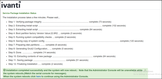
The system performs actions, which requires multiple reboots as part of the upgrade.
After the upgrade to the Secure Boot build (detailed above) is complete, the images on an ICS would look like the following:

Deploying Virtual ICS from OVF
ICS 25.1.0.0 needs vTPM to be enabled at the ESXi infrastructure. To enable vTPM, you need VMware vSphere and a key provider, such as Native Key Provider. vTPM and Native Key Provider are licensed for use in all vSphere versions. Supported ESXi versions are 7.0.x and 8.0.x.
vTPM is a VMware component, and for the latest documentation please refer to VMware product documentation.
To deploy Virtual ICS (vICS) from OVF:
1.Select Compute > vApps > New, and then select the Add vAPP From OVF option.
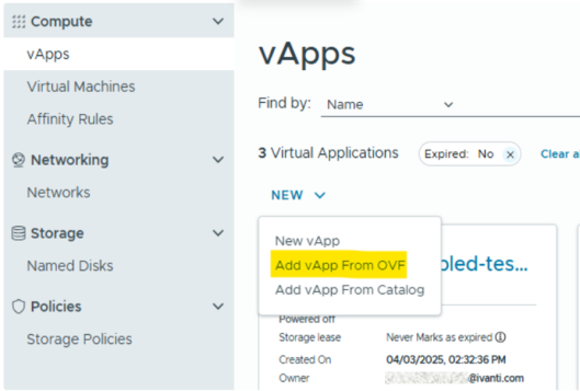
2.Select all three files (OVF, NVRAM, VMDK) required for deployment of vICS:
•OVF file - Select the OVF file based on your deployment requirement.
For example:
•ISA-V-VMWARE-ICS-25.1.0.0-<build-number>-VT-ISA8000-V.ovf
•ISA-V-VMWARE-ICS-25.1.0.0-<build-number>-VT-ISA6000-V.ovf
•ISA-V-VMWARE-ICS-25.1.0.0-<build-number>-VT-ISA4000-V.ovf
•NVRAM file - example: ISA-V-VMWARE-ICS-25.1.0.0-<build-number>-VT-file1.nvram
•VMDK file - example: ISA-V-VMWARE-ICS-25.1.0.0-<build-number>-VT-disk1.vmdk
3.Follow the wizard and configure the necessary details as per your requirement. Click Finish.
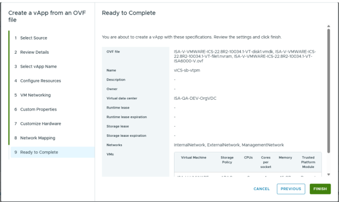
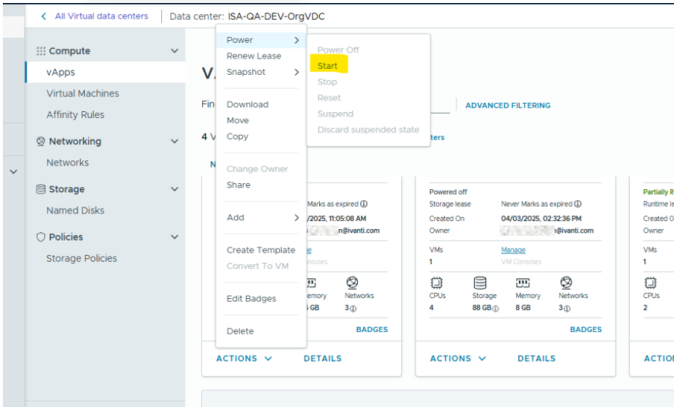
4.Click Start to power on vICS.
vTPM on ESXi 8.0.x
No additional steps are required to add vTPM when the ESXi itself is enabled with vTPM support.
Prerequisites
•vCenter license
•ESXi license
•Key Management Server on vCenter
•vTPM requirements as specified by Broadcom vTPM Requirements
vTPM on ESXi 7.x
If ESXi 7.2 is used as hypervisor, then vTPM does not get attached automatically on deploying virtual ICS. Attach vTPM by selecting Settings > ADD NEW DEVICE > Trusted Platform Module.
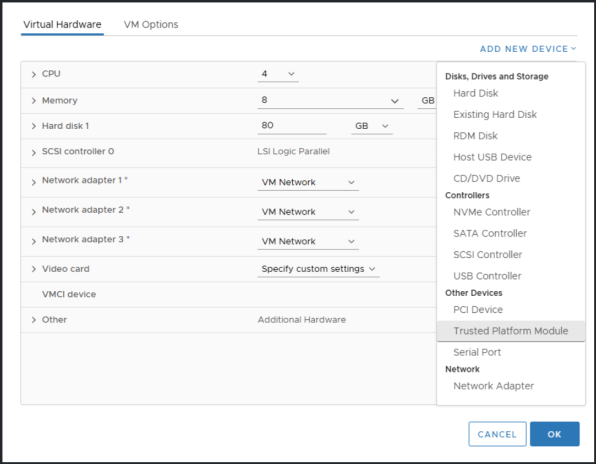
Due to VMware limitations, sometimes Trusted Platform Module is not visible in ADD NEW DEVICE option. In such scenario, follow the below steps.
1.Navigate to Settings > VM Options > General Options.
2.Change Guest OS Family from Other to Linux.
3.Change Guest OS Version from Other (64-bit) to TPM supported version like Ubuntu Linux (64-bit).
4.Click OK.
5.Attach vTPM by selecting Settings > ADD NEW DEVICE > Trusted Platform Module.
6.Revert Guest OS Family from Linux to Other.
7.Revert Guest OS Version from TPM supported version like Ubuntu Linux (64-bit) to Other (64-bit).
Limitations
•Removing vTPM from virtual ICS can make virtual ICS non recoverable.
•Cloning virtual ICS with replace TPM option is not supported.
•Exporting virtual ICS with vTPM to template is not supported by VMware.
25.1.1.0 Release
•Deploying Ivanti Connect Secure Appliance on Hyper-V
•Deploying Ivanti Connect Secure Appliance on OpenStack KVM
•Deploying Ivanti Connect Secure Appliance on Azure
Deploying Ivanti Connect Secure Appliance on Hyper-V
Overview of ICS Hyper-V Enablement
Ivanti Security Appliance are now supported on Microsoft's Hyper-V hypervisor in addition to VMWare platform.
The following table contains data regarding the Number of cores to be allocated to each Hyper-V model:
|
Platform |
Cores Per VM |
RAM |
Disk Space |
|---|---|---|---|
|
ISA4000-V |
4 |
8 GB |
80 GB |
|
ISA6000-V |
8 |
16 GB |
80 GB |
|
ISA8000-V |
12 |
32 GB |
80 GB |
Limitations
•Hyper-V Deployment with secure boot is only qualified for ICS 25.1.1.0 release onwards.
•Upgrade from 22.X to 25.X as well as rollback from 25.1.1.0 to any older release is not supported.
•Only Fresh install is supported.
•The image supports only IDE disks and will support only the ‘Generation 2’ type of Virtual machine in Hyper-V Manager because secure-boot is only supported on Gen2 onwards.
•VM Cloning is no longer a valid scenario because for every VM we should store unique keys in TPM, hence we can’t use same TPM while cloning.
Deploying a Hyper-V ISA-V through the Hyper-V Manager
To deploy a Ivanti Security appliance through the Hyper-V Manager:
1.Copy the Hyper-V ISA-V Package to the Hyper-V Server.
2.Open Hyper-V Manager.
3.Deploy Hyper-V ISA-V.
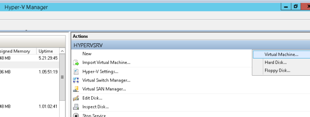
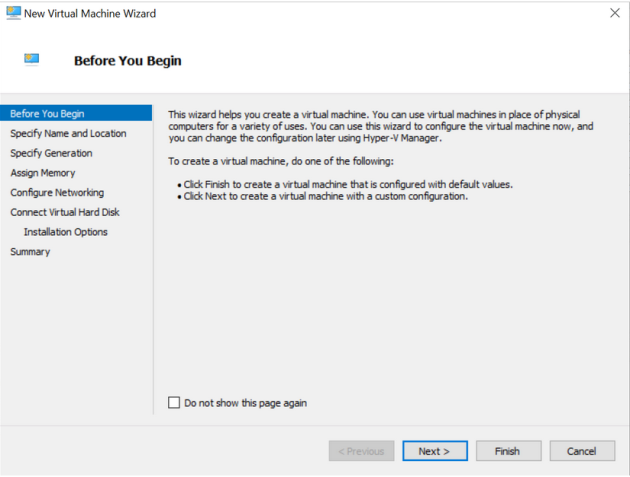
4.On the Before you Begin screen, click Next.
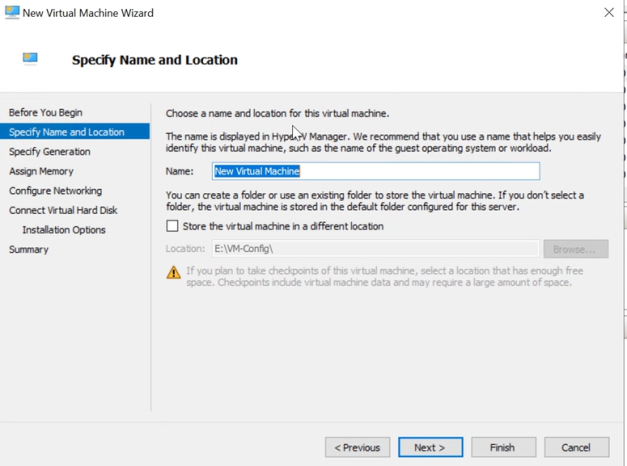
5.Enter Specify Name and Location and click Next.
6.Select Generation 2 only as Hyper-V ISA-V does not support older Generation 1, and click Next.
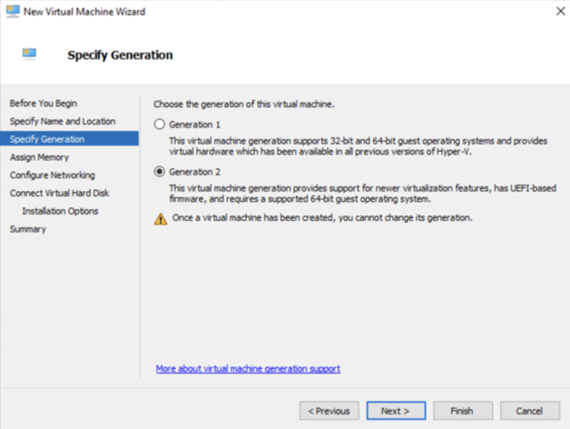
7.Now assign the appropriate memory. Enter 8192 MB for ISA-V, and click Next.
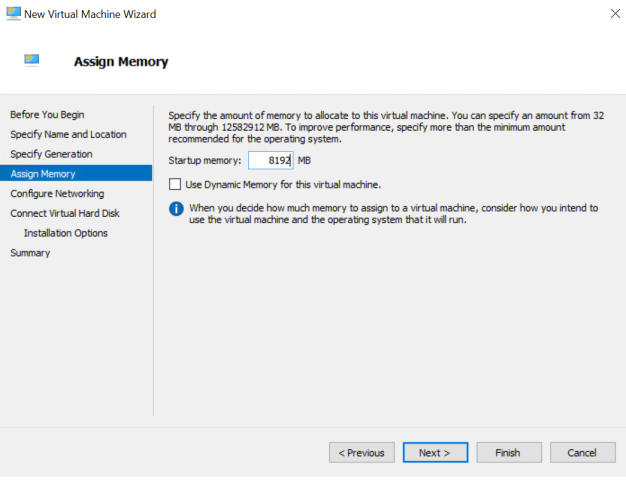
8.The Configure Networking page opens. Select a virtual switch to be used by the network adapter, and click Next.
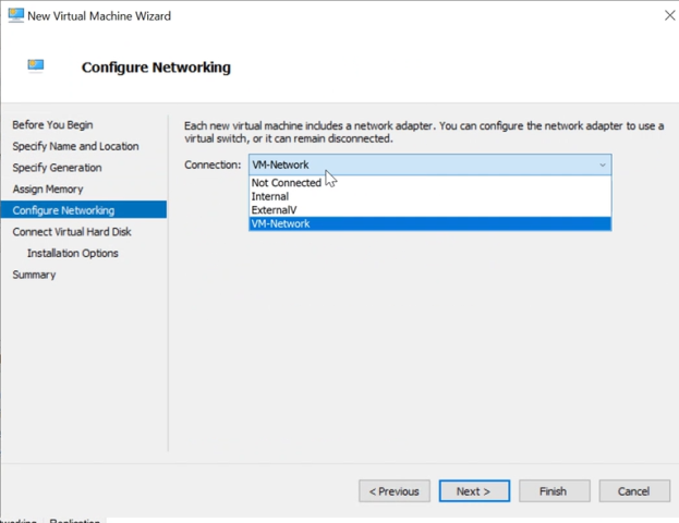
9. The Connect Virtual Hard Disk page appears. Select the Use an existing virtual hard disk button and provide the location of the Hyper-V ISA-V package.vhdx (step 1).
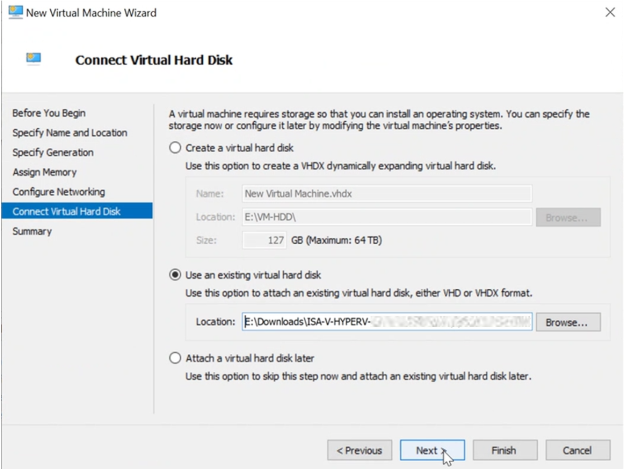
10. Click on Finish. Hyper-V Server creates an entry under Virtual Machines.
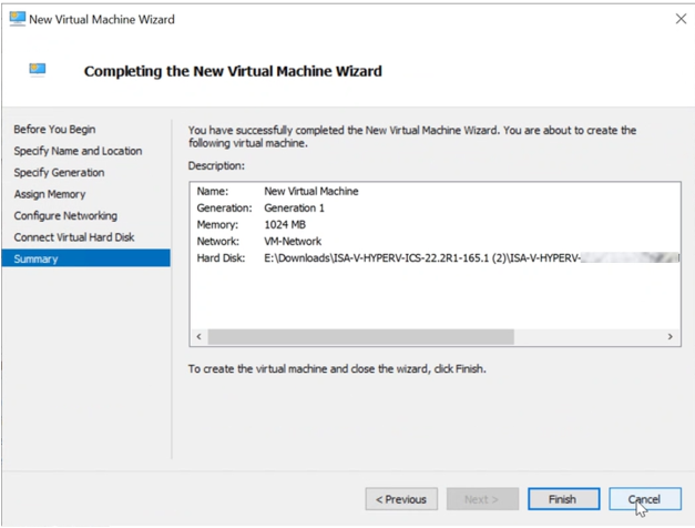
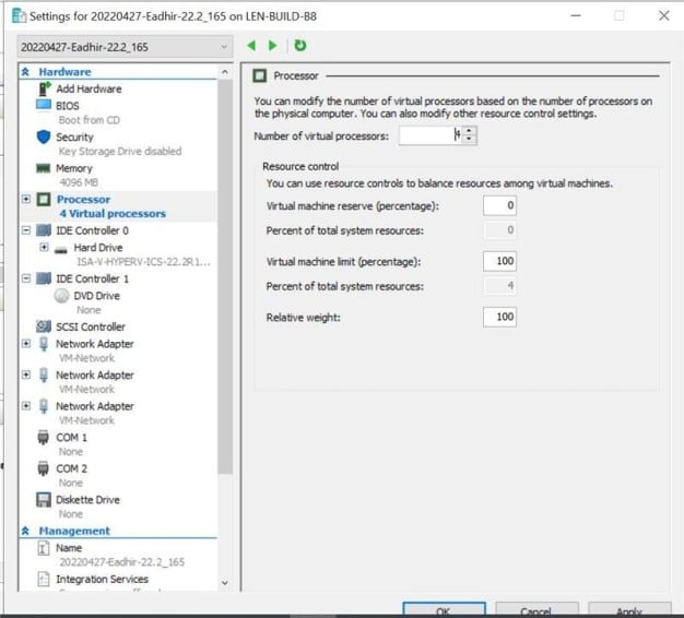
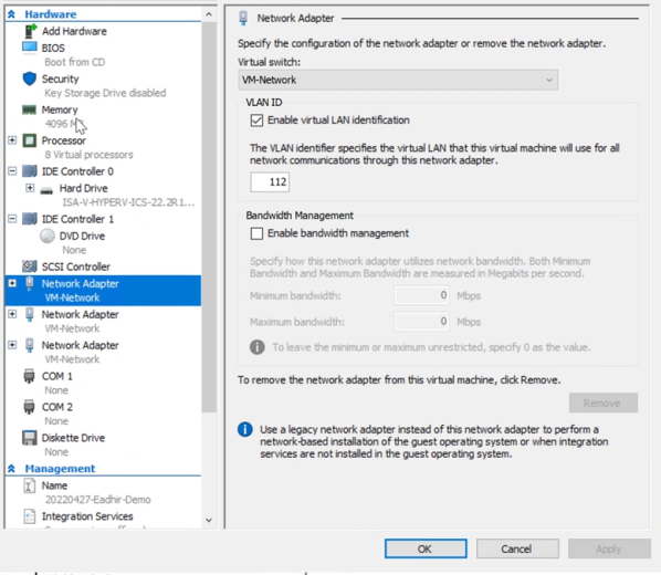
11. Now, add number on vCPUs and network adapter for External Port and Management Port.
a. Right click on the VM Name, and click on Settings.
b. Enter Number of virtual processors required.
c. In the dialog box that opens, click on Add Hardware in the left pane.
d. On the right pane, select Network Adapter.
e. Click on Add.
It is important to add all the three network adapters to Hyper-V ISA-V before powering on the VM. Adding network adapters after powering-on the Hyper-V ISA-V may result in network connectivity issues. The following list indicates the order of virtual adapters:
1. Network Adapter: Internal
2. Network Adapter 2: External
3. Network Adapter 3: Management
12. Select the virtual switch for External Port, and click on Apply.
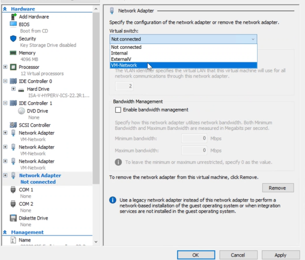
13. Now add network adapter for Management port.
a. Click on Add Hardware on the left pane. Select Network Adapter, click on Add.
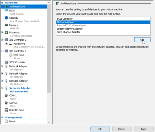
b. Select the Virtual Switch for Management Port, and click on Apply.
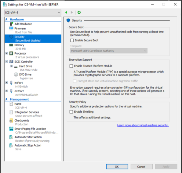
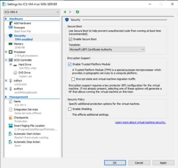
14. Before starting the virtual machine, go to Settings > Security.
a. Change the Template to Microsoft UEFI Certificate Authority.
b. Clear the Enable Secure Boot option to disable it before the first boot.
c. Clear the Enable Trusted Platform Module option to disable TPM for the first boot.
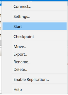
15. Select Start to power on the virtual machine.
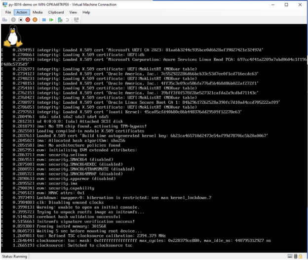
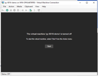
16. Virtual machine will boot, and it will automatically shut down when it detects Secure Boot is disabled. This step is very much needed, as it will install Ivanti Secure Boot certificate in this first boot. The following screenshot may or may not appear during the fast booting process and after the system is turned off.
17. Before starting the virtual machine again, go to Settings > Security.
a. Make sure the Template is Microsoft UEFI Certificate Authority.
b. Select the Enable Secure Boot option.
c. Select the Enable Trusted Platform Module option.
d. Optional step is to add a DVD drive with automatic initial configurations For details, see Deploying Connect Secure with Automatic Initial Configurations.
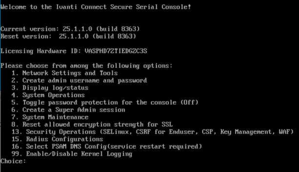
18. Select Start to power on the virtual machine.
Once Deployment is successful, the deployed VM Console is shown.
Deploying Connect Secure with Automatic Initial Configurations
1.Download the Hyper-V package file and find the hyperv_template.xml file.
2.Customize the required fields like IP address/Subnet Mask/Default Gateway for internal, external, and management ports and then convert to .iso image (hyperv.iso) using the following command.
Command Sample: mkisofs -l -o hyperv.iso hyperv_template.xml.
3.Under DVD Drive, click Browse and upload the .iso file and then start the VM.
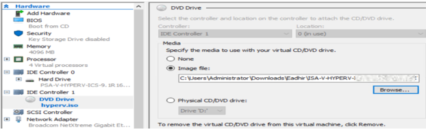
4.You can add DVD Drive when the virtual machine is switched off automatically after the first.
Note:
When deploying a Hyper-V image using a script (.ps1 file), it is essential to use the file name hyperv_template.xml with the mkisofs command. If you use any other file name, the deployment will not recognize hyperv.iso as a drive.
For example, the following commands will not work:
mkisofs -l -o hyperv.iso hyperv_template-AP.xml
mkisofs -l -o hyperv.iso hyperv_template-AP1.xml
or
with any other file name in place of hyperv_template.xml.
Always use the file name hyperv_template.xml with the mkisofs command:
mkisofs -l -o hyperv.iso hyperv_template.xml
Deploying a Hyper-V ISA-V through Powershell cmdlets
To deploy a Hyper-V ISA-V through Powershell cmdlets:
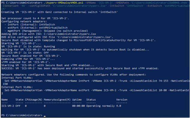
•either run the powershell commands manually from powershell script "hyperv-VMDeployVHDX.ps1".
•or call the powershell script(Method1) with proper arguments to automate all the steps and directly get a running VM with secure boot enabled.
Launch Hyper-V ISA-V in an automated fashion with secure boot enabled.
1.Copy the Hyper-V ISA-V Package and hyperv-VMDeployVHDX.ps1 to the Hyper-V Server.
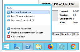
2.Open PowerShell as administrator.
3.PowerShell script takes the following inputs:
•VMName: Name of the VM to create (mandatory)
•VHDXPath: Path to the existing VHDX file (mandatory)
•ISAVariant: ISA variant determining VM resources - "4K", "6K", or "8K" (mandatory)
•4K: 8GB RAM, 4 vCPUs
•6K: 16GB RAM, 8 vCPUs
•8K: 32GB RAM, 12 vCPUs
•IntSwitch: Name of the Hyper-V virtual switch for Internal network adapter (mandatory)
•ExtSwitch: Name of the Hyper-V virtual switch for External network adapter (mandatory)
•MgmtSwitch: Name of the Hyper-V virtual switch for Management network adapter (optional)
•ConfigISOPath: Path to an ISO file to mount as a DVD drive for auto configuration (optional)
4.Keep the VMName, VHDXPath, ISAVariant, Internal Switch name, External Switch name ready.
5.Example deployment commands:
With all three network adapters:

With Internal and External adapters only:

Cloning of VM on Hyper-V
Cloning is no longer supported for Generation 2 VMs because of TPM (Trusted platform modules) limitations.
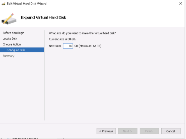
Increasing the Disk Size in Hyper-V
Fresh installation 80 GB disk space is available by default. You can modify or increase the disk size only once on fresh installation or upgrade of the ICS images, but not on rollback or factory reset images.
To increase the disk space:
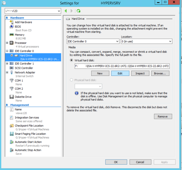
1.Click IDE Controller > Hardware, click Edit.
2.Select Expand and click Next>.
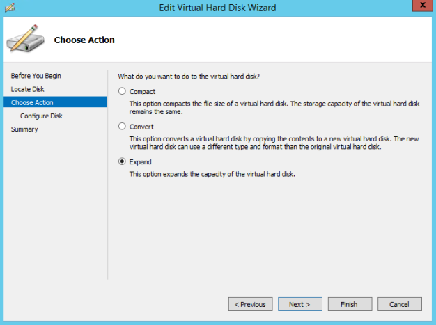
3.Change the disk size in GB and click Finish.
ICS Provisioning Parameters
Provisioning parameters are those parameters which are required during the deployment of a virtual appliance. ICS accepts the following parameters as provisioning parameters in the XML format.
|
<PropertySection> <Property oe:key="vaIPAddress" oe:value=""/> <Property oe:key="vaNetmask" oe:value=""/> <Property oe:key="vaGateway" oe:value=""/> <Property oe:key="vaDefaultVlan" oe:value=""/> <Property oe:key="vaExternalIPAddress" oe:value=""/> <Property oe:key="vaExternalNetmask" oe:value=""/> <Property oe:key="vaExternalGateway" oe:value=""/> <Property oe:key="vaExternalDefaultVlan" oe:value=""/> <Property oe:key="vaManagementIPAddress" oe:value=""/> <Property oe:key="vaManagementNetmask" oe:value=""/> <Property oe:key="vaManagementGateway" oe:value=""/> <Property oe:key="vaManagementDefaultVlan" oe:value=""/> <Property oe:key="vaPrimaryDNS" oe:value=""/> <Property oe:key="vaSecondaryDNS" oe:value=""/> <Property oe:key="vaWINSServer" oe:value="1.2.3.4"/> <Property oe:key="vaDNSDomain" oe:value="ics.company.com"/> <Property oe:key="vaAdminUsername" oe:value="admin"/> <Property oe:key="vaAdminPassword" oe:value="Password123$"/> <Property oe:key="vaCommonName" oe:value="ics-ext-port.company.com"/> <Property oe:key="vaOrganization" oe:value="Ivanti"/> <Property oe:key="vaRandomText" oe:value="randomtextrandomtextrandomtextrandomtext"/> <Property oe:key="vaAcceptLicenseAgreement" oe:value="y"/> <Property oe:key="vaEnableLicenseServer" oe:value="n"/> <Property oe:key="vaAdminEnableREST" oe:value=""/> <Property oe:key="vaAuthCodeLicense" oe:value=""/> <Property oe:key="vaConfigURL" oe:value="http://a.b.c.d/ics_config.xml"/> <Property oe:key="vaConfigServerCACertPEM" oe:value=""/> <Property oe:key="vaConfigData" oe:value=""/> <Property oe:key="vaInternalPortReconfigWithValueInVAppProperties" oe:value="1"/> <Property oe:key="vaManagementPortReconfigWithValueInVAppProperties" oe:value="1"/> <Property oe:key="vaExternalPortReconfigWithValueInVAppProperties" oe:value="1"/> </PropertySection> |
|
Parameter Name |
Type |
Description |
|---|---|---|
|
vaIPAddress |
IP address |
Internal interface IP |
|
vaNetmask |
IP address |
Internal interface subnet mask |
|
vaGateway |
IP address |
Internal interface IP gateway |
|
vaDefaultVlan |
integer |
VLAN number to assign to this interface |
|
vaExternalIPAddress |
IP address |
External interface IP |
|
vaExternalNetmask |
IP address |
External interface subnet mask |
|
vaExternalGateway |
IP address |
External interface IP gateway |
|
vaExternalDefaultVlan |
integer |
VLAN number to assign to this interface |
|
vaManagementIPAddress |
IP address |
Management interface IP |
|
vaManagementNetmask |
IP address |
Management interface subnet mask |
|
vaManagementGateway |
IP address |
Management interface IP gateway |
|
vaExternalDefaultVlan |
integer |
VLAN number to assign to this interface |
|
vaPrimaryDNS |
IP address |
Primary DNS IP |
|
vaSecondaryDNS |
IP address |
Secondary DNS IP |
|
vaWINSServer |
IP address |
Windows server IP |
|
vaDNSDomain |
string |
Windows domain name |
|
VaAdminUsername |
string |
Admin username |
|
vaAdminPassword |
string |
Admin password |
|
vaCommonName |
string |
Common name |
|
vaOrganization |
string |
Organization name |
|
vaRandomText |
string |
Random text to generate self-signed certificate |
|
vaAcceptLicenseAgreement |
character |
“y” to accept the license agreement |
|
vaEnableLicenseServer |
character |
“y” to enable it as VLS server. “n” to bring it up as a ICS node. |
|
vaAdminEnableREST |
character |
“y” to enable REST for administrator user |
|
vaAuthCodeLicense |
string |
Authentication code that needs to be obtained from Ivanti. |
|
vaConfigURL |
string URL |
Http based URL where XML based ICS configuration can be found. |
|
vaConfigServerCACertPEM |
string |
PEM format of CA certificate. |
|
vaConfigData |
string |
base64 encoded XML based ICS configuration. |
|
vaInternalPortReconfigWithValueIn VAppProperties |
integer |
The Internal port overwrite property. If set to 1, overwrites the virtual appliance’s internal port settings with the ones specified during deployment. Set this value as 1. |
|
vaManagementPortReconfigWithValueIn VAppProperties |
integer |
The Management port overwrite property. If set to 1, overwrites the management port-related parameters in the ICS with the ones defined here. Set this value as 1. |
|
vaExternalPortReconfigWithValueIn VAppProperties |
integer |
The External port overwrite property. If set to 1, overwrite the external port-related parameters in ICS/IPS with the ones defined here. Set this value as 1. |
v6 Parameters
| Parameter | Type | Description |
|---|---|---|
| vaNetworkStack | IPv4 or IPv6 address |
It indicates network address configured during deployment. v4 : IPv4 addresses are allowed to configured. v6 : IPv6 addresses are allowed to configured. Both: IPv4 and IPv6 addresses are allowed to configured. |
| vaIPv6Address | IPv6 address | Internal interface IPv6 address |
|
vaPrefix |
IPv6 address |
Internal interface IPv6 prefix length. |
|
vaIPv6Gateway |
IPv6 address |
Internal interface IPv6 gateway address. |
|
vaManagementIPv6Address |
IPv6 address |
Management interface IPv6 address |
|
vaManagementPrefix |
IPv6 address |
Management interface IPv6 prefix length. |
|
vaManagementIPv6Gateway |
IPv6 address |
Management interface IPv6 gateway address. |
|
vaExternalIPv6Address |
IPv6 address |
External interface IPv6 address |
|
vaExternalPrefix |
IPv6 address |
External interface IPv6 prefix length. |
|
vaExternalIPv6Gateway |
IPv6 address |
External interface IPv6 gateway address. |
ICS supports zero touch provisioning. This feature can detect and assign DHCP networking settings automatically at the ICS boot up. The following ICS parameters should be set to null in order to fetch the networking configuration automatically from the DHCP server.
|
vaIPAddress |
vaExternalIPAddress |
vaManagementIPAddress |
vaNetworkStack |
vaManagementIPv6Address |
vaExternalPrefix |
|
vaNetmask |
vaExternalNetmask |
vaManagementNetmask |
vaIPv6Address |
vaManagementPrefix |
vaExternalIPv6Gateway |
|
vaGateway |
vaExternalGateway |
vaManagementGateway |
vaPrefix |
vaManagementIPv6Gateway |
|
|
vaPrimaryDNS |
vaSecondaryDNS |
vaDNSDomain |
vaIPv6Gateway |
vaExternalIPv6Address |
Deploying Ivanti Connect Secure Appliance on OpenStack KVM
Overview
Assumptions
The basic understanding of deployment models of ICS on a data center and basic experience in using OpenStack is needed for the better understanding of this guide.
Prerequisites and System Requirements
The OpenStack Fabric has various components such as Controller, Compute, Identity, Image, Networking etc. that are separately installed. For details about these services,
To deploy the ICS VA on OpenStack, you need the following:
•Access to the OpenStack Dashboard
•An OpenStack account with deployment rights
•ICS KVM Image
•(Optional) ICS licenses
•(Optional) ICS configuration in xml format, required only for zero touch deployment
•Desired flavors of ISA-V (ISA4000-V, ISA6000-V, ISA8000-V).
•Desired ICS KVM image on OpenStack
•Internal, External and Management networks on OpenStack
•Security Groups for Internal, External and Management Ports
•Compute nodes should support vTPM.
•Compute nodes should support secure boot for virtual machines.
•Compute nodes should have Ivanti released OVMF firmware binary (OVMF_CODE.secboot.ivanti.fd) and NVRAM file (OVMF_VARS_4M.ivanti.fd) for secure boot.
Deploying ICS on OpenStack Using Horizon Dashboard
Before proceeding with the ICS deployment, ensure that the necessary prerequisites are set up. For details, see Appendix A: Setting Up Prerequisites
To deploy ICS on OpenStack, do the following:
1.Log in to the OpenStack.
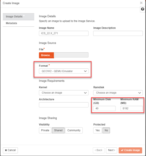
2.In the OpenStack dashboard displayed, select Project > Compute > Imagesand then create an image. For more information, see Create Image.
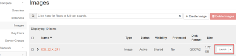
3.From the list of images displayed, click on Launch corresponding to the ICS KVM image you want to launch.
Image selected must have following attributes for secure boot and vTPM supported ICS image.
•hw_disk_bus='virtio'
•hw_firmware_type='uefi'
•hw_machine_type='q35'
•hw_tpm_model='tpm-crb'
•hw_tpm_version='2.0'
•os_secure_boot='required'
The following figure depicts the ICS VA Images screen:
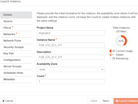
4.In the Launch Instance Details window, fill the following and then click Next.
•Instance Name: Specify host name of the ICS Virtual instance
•Description: Enter a brief description on this instance
•Availability Zone: Select the zone where the instance is deployed
•Count: Number of VM instances
The following figure depicts the Device Details screen:
5.The Source window displays the details of the image used. Click Next.
The following figure depicts the Source Selection screen.
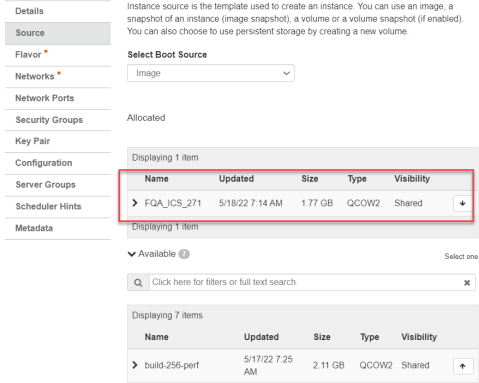
6.In the Flavor window, select required flavors of ISA-V (ISA4000-V, ISA6000-V, ISA8000-V) from the list based on the memory and storage capacity of the instance. Click Next.
The following figure depicts the Flavor Selection screen.
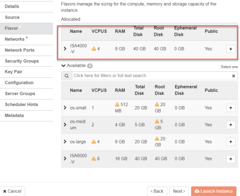
7.In the Networks window, select networks from the list that specifies internal, external and management subnets. ICS supports VM with 2-NICs model and 3-NICs model for deployment. Click Next.
The following figure depicts the Network Selection screen:
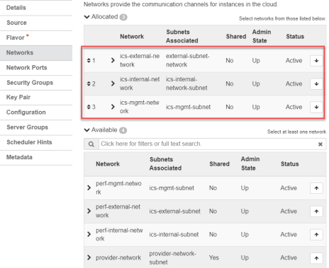
8.(Optional) Network Ports window. Click Next.
The following figure depicts the Network Ports Selection screen:
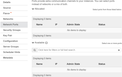
9.In the Security Groups window, select the required network security groups from the list for internal, external and management ports. Click Next. To create new security groups, refer Creating Required Security Groups for Internal, External and Management Ports
The following figure depicts the Security Groups Selection screen:
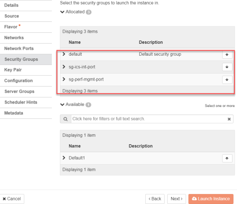
10.Key Pair is not used. Click Next.
The following figure depicts the Key Pair screen:
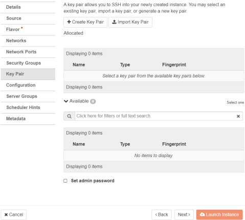
11.Click Choose File and import the file that contains the provisioning parameters in XML format OR paste the Customization script and do the required modifications. Select the Configuration Drive check box. The template file is available for ISA-V instance and click Launch Instance upon selecting the Configuration Drive option.
The following figure depicts the Configuration Script screen:
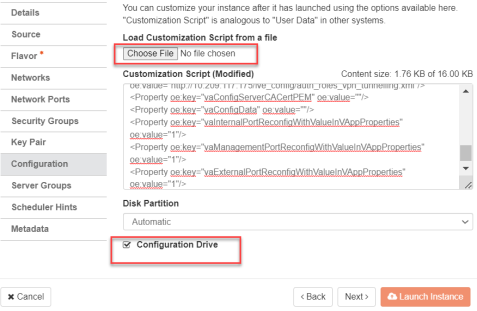
12.The Instances window lists all the ICS VA instances. The blue bar in the Task column shows the status of creation of the instance. This will take a few minutes.
Open the created ICS VA instance by clicking on the Instance Name link.
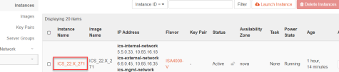
The Interface tab shows the networks that are created.

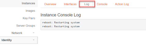
The Log tab shows the log details of the device that is created.
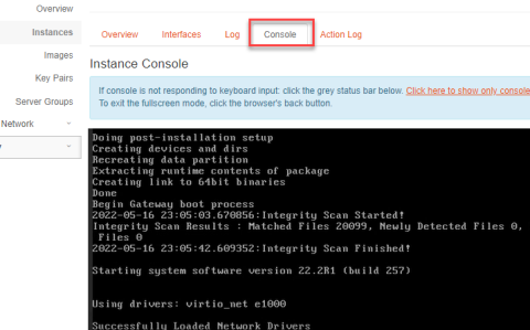
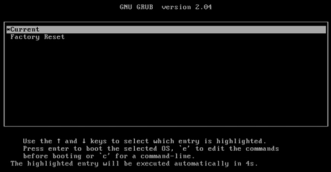
The console tab provides the virtual console to view the device coming up.
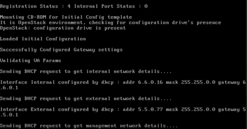
13.Next, the Internal and External interfaces are configured by DHCP (Zero touch configuration).
The following figure depicts the Internal and External Interfaces Configuration by DHCP screen:
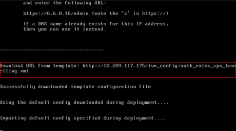
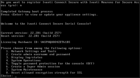
14.The Config URL is downloaded for initial configuration.
The following figure depicts the Download Config URL from Template screen:
ICS Provisioning Parameters
Provisioning parameters are those parameters which are required during the deployment of a virtual appliance. ICS accepts the following parameters as provisioning parameters in the XML format.
|
<PropertySection> <Property oe:key="vaIPAddress" oe:value=""/> <Property oe:key="vaNetmask" oe:value=""/> <Property oe:key="vaGateway" oe:value=""/> <Property oe:key="vaDefaultVlan" oe:value=""/> <Property oe:key="vaExternalIPAddress" oe:value=""/> <Property oe:key="vaExternalNetmask" oe:value=""/> <Property oe:key="vaExternalGateway" oe:value=""/> <Property oe:key="vaExternalDefaultVlan" oe:value=""/> <Property oe:key="vaManagementIPAddress" oe:value=""/> <Property oe:key="vaManagementNetmask" oe:value=""/> <Property oe:key="vaManagementGateway" oe:value=""/> <Property oe:key="vaManagementDefaultVlan" oe:value=""/> <Property oe:key="vaPrimaryDNS" oe:value=""/> <Property oe:key="vaSecondaryDNS" oe:value=""/> <Property oe:key="vaWINSServer" oe:value="1.2.3.4"/> <Property oe:key="vaDNSDomain" oe:value="ics.company.com"/> <Property oe:key="vaAdminUsername" oe:value="admindb"/> <Property oe:key="vaAdminPassword" oe:value="Password123$"/> <Property oe:key="vaCommonName" oe:value="ics-ext-port.company.com"/> <Property oe:key="vaOrganization" oe:value="Ivanti"/> <Property oe:key="vaRandomText" oe:value="randomtextrandomtextrandomtextrandomtext"/> <Property oe:key="vaAcceptLicenseAgreement" oe:value="y"/> <Property oe:key="vaEnableLicenseServer" oe:value="n"/> <Property oe:key="vaAdminEnableREST" oe:value=""/> <Property oe:key="vaAuthCodeLicense" oe:value=""/> <Property oe:key="vaConfigURL" oe:value="http://a.b.c.d/ics_config.xml"/> <Property oe:key="vaConfigServerCACertPEM" oe:value=""/> <Property oe:key="vaConfigData" oe:value=""/> <Property oe:key="vaInternalPortReconfigWithValueInVAppProperties" oe:value="1"/> <Property oe:key="vaManagementPortReconfigWithValueInVAppProperties" oe:value="1"/> <Property oe:key="vaExternalPortReconfigWithValueInVAppProperties" oe:value="1"/> </PropertySection> |
|
Parameter Name |
Type |
Description |
|---|---|---|
|
vaIPAddress |
IP address |
Internal interface IP |
|
vaNetmask |
IP address |
Internal interface subnet mask |
|
vaGateway |
IP address |
Internal interface IP gateway |
|
vaDefaultVlan |
integer |
VLAN number to assign to this interface |
|
vaExternalIPAddress |
IP address |
External interface IP |
|
vaExternalNetmask |
IP address |
External interface subnet mask |
|
vaExternalGateway |
IP address |
External interface IP gateway |
|
vaExternalDefaultVlan |
Integer |
VLAN number to assign to this interface. |
|
vaManagementIPAddress |
IP address |
Management interface IP |
|
vaManagementNetmask |
IP address |
Management interface subnet mask |
|
vaManagementGateway |
IP address |
Management interface IP gateway |
|
vaManagementDefaultVlan |
Integer |
VLAN number to assign to this interface |
|
vaPrimaryDNS |
IP address |
Primary DNS IP |
|
vaSecondaryDNS |
IP address |
Secondary DNS IP |
|
vaWINSServer |
IP address |
Windows server IP |
|
vaDNSDomain |
string |
Windows domain name |
|
VaAdminUsername |
string |
Admin username |
|
vaAdminPassword |
string |
Admin password |
|
vaCommonName |
string |
Common name |
|
vaOrganization |
string |
Organization name |
|
vaRandomText |
string |
Random text to generate self-signed certificate |
|
vaAcceptLicenseAgreement |
character |
“y” to accept the license agreement |
|
vaEnableLicenseServer |
character |
“y” to enable it as VLS server. “n” to bring it up as a ICS node. |
|
vaAdminEnableREST |
character |
“y” to enable REST for administrator user |
|
vaAuthCodeLicense |
string |
Authentication code that needs to be obtained from Ivanti. |
|
vaConfigURL |
String URL |
Http based URL where XML based ICS configuration can be found. |
|
vaConfigServerCACertPEM |
string |
PEM format of CA certificate. |
|
vaConfigData |
string |
base64 encoded XML based ICS configuration. |
|
vaInternalPortReconfigWithValueIn |
integer |
The Internal port overwrite property. If set to 1, overwrite the virtual appliance’s internal port settings with the ones specified during deployment. Set this value as 1. |
|
vaManagementPortReconfigWithValueIn |
integer |
The Management port overwrite property. If set to 1, overwrite the management port-related parameters in the ICS with the ones defined here. Set this value as 1. |
|
vaExternalPortReconfigWithValueIn |
integer |
The External port overwrite property. If set to 1, overwrite the external port-related parameters in ICS/IPS with the ones defined here. Set this value as 1. |
IICS supports zero touch provisioning. This feature can detect and assign DHCP networking settings automatically at the ICS boot up. The following ICS parameters should be set to null in order to fetch the networking configuration automatically from the DHCP server.
|
•vaIPAddress |
•vaExternalIPAddress |
•vaManagementIPAddress |
|
•vaNetmask |
•vaExternalNetmask |
•vaManagementNetmask |
|
•vaGateway |
•vaExternalGateway |
•vaManagementGateway |
|
•vaPrimaryDNS |
•vaSecondaryDNS |
•vaDNSDomain |
Leased IP from DHCP server should be valid for a long time as ICS does not request for DHCP renewals.
vTPM and Secure Boot Support on OpenStack
This section provides guidance on enabling virtual Trusted Platform Module (vTPM) and Secure Boot features for Ivanti Connect Secure virtual appliances deployed on OpenStack. Implementing vTPM and Secure Boot improves data protection by supporting encrypted secrets and secure firmware validation.
vTPM Overview
This section describes the process and prerequisites for enabling vTPM (virtual Trusted Platform Module) and Secure Boot for Ivanti Connect Secure virtual appliances on OpenStack. Enabling these security features ensures that sensitive data such as encryption keys are stored securely and validates the integrity of the virtual appliance firmware during boot. The guidance provided here will help you configure a compliant and robust OpenStack environment for secure ICS deployments.
Enabling vTPM
To enable vTPM (virtual Trusted Platform Module) support on OpenStack for Ivanti Connect Secure virtual appliances, ensure the following requirements and steps are met on each compute host:
Prerequisites:
•An OpenStack key manager service, such as Barbican, must be deployed and configured on the controller node. This service is required to store the secrets used for encrypting virtual device files at rest.
•The user deploying the ICS virtual appliance must have the creator role in the corresponding OpenStack project to allow Barbican to create ICS secrets.
•The swtpm binary and associated libraries must be installed on each compute node
•/etc/nova/nova-compute.conf should have following configuration to support virtual TPM.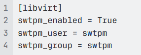
•Set the  config option to 'True' in
 of compute node. This will enable support for both TPM version 1.2 and 2.0.
With the above requirements satisfied, verify vTPM support by inspecting the traits on the compute node’s resource provider:
Enabling Secure Boot
To enable UEFI secure boot on OpenStack, follow steps as per OpenStack documentation.
You can verify UEFI Secure Boot support by inspecting the traits on the compute node’s resource provider:
In order to boot Ivanti virtual ICS in secure boot mode, perform following steps.
1.Extract Ivanti released OVMF firmware and VARS file from KVM ZIP artifact.
2.Ivanti released OVMF firmware and VARS file needs to be copied to /usr/share/OVMF directory of compute nodes.
Ivanti released VARS file has secure boot certificate required to boot virtual ICS in secure boot mode.
3.Copy 40-edk2-x86_64-secure-enrolled.json to 10-edk2-x86_64-secure-enrolled.json and modify 10-edk2-x86_64-secure-enrolled.json file in /usr/share/qemu/firmware directory to use Ivanti’s secure boot OVMF files.
b. Following contents need to be changed to use Ivanti’s released OVMF files.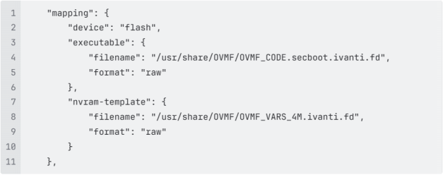
4.Restart libvirtd and nova-compute on compute nodes
Setting Virtual ICS Image Attributes
Following attributes need to be set to enable secure boot for virtual ICS.
1.Select virtual ICS image.
2.Edit image.
3.Select Metadata section.
4.Update following attributes.
•hw_disk_bus='virtio'
•hw_firmware_type='uefi'
•hw_machine_type='q35'
•hw_tpm_model='tpm-crb'
•hw_tpm_version='2.0'
•os_secure_boot='required'
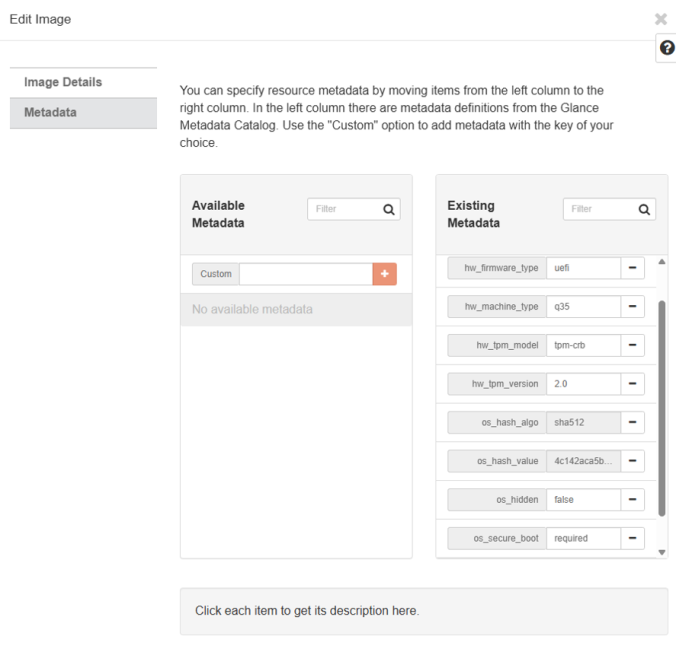
If above listed attributes are enabled then virtual ICS will boot with secure boot enabled and vTPM attached.
OpenStack Limitations
1.Snapshot and Restore functionality does not work in OpenStack for ICS with vTPM.
a. Source
b. Spawning from an image created by snapshotting a VM with a vTPM will result in a fresh, empty vTPM
2.Operations like “hard reboot” or “shut off/start” may fail to start ICS with vTPM. Refer Bug link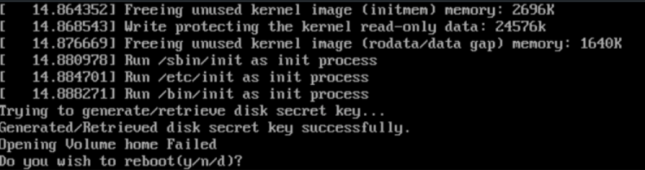
a. Above error may be seen.
b. OpenStack fix link is needed to solve this issue.
c. Alternately, following workaround can be added in your OpenStack environment.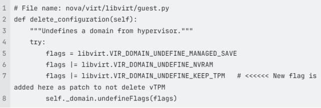
Deploying Ivanti Connect Secure Appliance on Azure
Prerequisites and System Requirements on Azure
To deploy the Ivanti Connect Secure Virtual Appliance on Azure custom deployment, you need the following:
•A Microsoft Azure account
•Access to the Microsoft Azure portal (https://portal.azure.com)
•Ivanti Connect Secure Virtual Appliance Image (.vhd file).
•Azure Resource Manager template (ARM template)
Supported Platform Systems
This section helps you in choosing the instance types that should be deployed with Ivanti Connect Secure for Azure.
•ISA4000-V
•ISA6000-V
•ISA8000-V
Create a Resource Group
To create a Resource group, do the following:
1.Log into Azure portal.
2.Navigate to Resource Groups. Enter unique resource group name.
3.Click Review + create to finalize and create resource group.
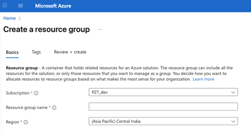
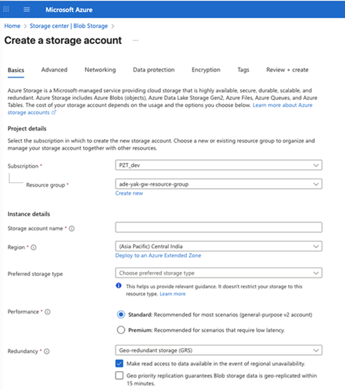
Create a Storage Account
To create a Storage Account, do the following:
1.Log in to the Azure portal.
2.Click New and create a Storage Account.
3.Choose the resource group you have already created.
4.Enter a unique name for the storage account name.
5.Click Review + create to create storage account.
Upload ICS Appliance Image to Storage Account
To upload Ivanti Connect Secure Virtual Appliance image to Stroage Account, do the following:
1.Download the Azure ICS image file (ics-azure-isa-v-<releaseno>-<buildno>-package.zip) which is in the zipped format.
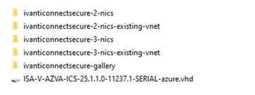
•The package contains the following components:
•ISA-V-AZVA-ICS-<releaseno>-<buildno>-SERIAL-azure.vhd: VHD disk image for Ivanti Connect Secure VA, to upload to Azure
•ivanticonnectsecure-gallery: Publish VHD as Shared Image Gallery image
•ivanticonnectsecure-2-nics: Deploy ICS with 2 NICs (new VNet)
•ivanticonnectsecure-2-nics-existing-vnet: Deploy ICS with 2 NICs (existing VNet)
•ivanticonnectsecure-3-nics: Deploy ICS with 3 NICs (new VNet)
•ivanticonnectsecure-3-nics-existing-vnet: Deploy ICS with 3 NICs (existing VNet)
•azuredeploy.json: ARM deployment templates
2.Unzip the file and look for the Ivanti Connect Secure Virtual Appliance vhd image.
3.Log in to the Azure portal.
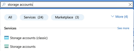
4.In the Azure portal, search for storage accounts and select the Storage Account you have created.
5.To upload ICS Virtual Appliance image. Select Storage browser in the left menu.
6.Click Blob containers and select your target container.
7.Click Upload at the top, browse for your file and hit the final Upload button and upload.
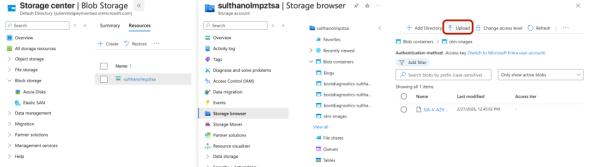
8.Inside your Storage Account, go to the left menu and click Storage browser under Data storage.
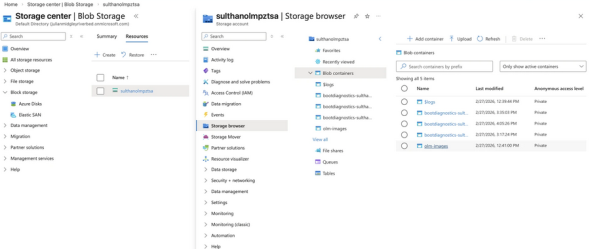
9.Under Blob containers, find and select your container (e.g., az-images) where the VHD file is uploaded.
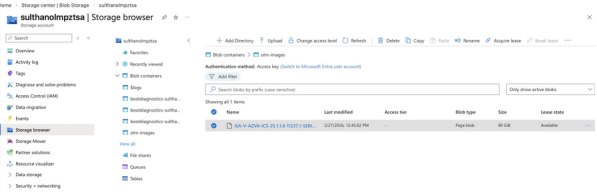
10.Inside the container, find your VHD file (e.g., ISA-V-AZVA-ICS-<releaseno>-<buildno>-SERIAL-azure.vhd). Click on the file to open its properties.
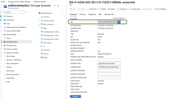
11.In the Overview or properties pane, look for the field named URL. Click the copy icon next to it.
The URL will be in this format: https://<name>.blob.core.windows.net/az-images/ISA-V-AZVA-ICS-<releaseno>-<buildno>-SERIAL-azure.vhd. This URL is need to deploy the Azure Gallery
Upload Azure Resource Manager Template to Gallery
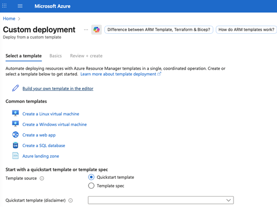
1.Navigate to Custom Deployment.
2.Select Build your template in the editor.
3.Locate the Azure Gallery deployment template file in folder (ivanticonnectsecure-gallery/azure-gallery-deploy.json).
4.Open this file and Copy its content and paste the into the designated field.
5.Click Save to apply the template.
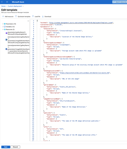
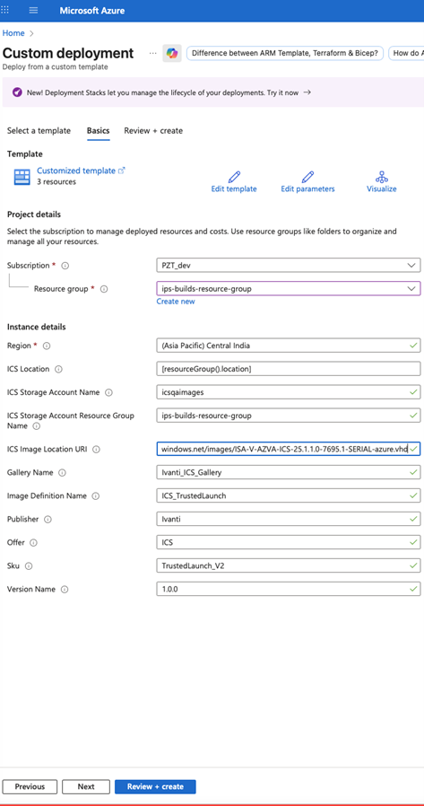
6.Fill or modify the following parameters:
•Region (mandatory): place
•ICS Location: Location of the Shared Image Gallery (Where Azrure Gallery image is deployed)
•Resource Group (mandatory): A resource group is a collection of resources that share the same lifecycle, permissions, and policies, where ICS is getting deployed
•ICS Storage Account Name: Storage account name where ICS image is uploaded
•ICS Storage Account Resource Group Name: Resource group of the existing storage account where ICS image is uploaded
•ICS Image Location URI: The is the URL to the location where ICS Azure vhd image is stored
•Gallery Name: The name of the Shared Image Gallery (this value is from Azure Gallery image)
•Image Definition Name: The name of the Image Definition (this value is from Azure Gallery image)
•Publisher: The name of the VM image definition publisher
•Offer: The name of the VM image definition offer
•SKU: The name of the VM image definition SKU
•Version Name: The VM image version name in semantic version pattern. The allowed characters are digit and period. For example: 0.0.1, 15.35.0. (this value is from Azure Gallery image)
 Azure Gallery Naming Restrictions
|
Resource Type |
Allowed Characters |
Disallowed Characters |
Length |
Start/End |
Rule Example |
|---|---|---|---|---|---|
| Gallery Name | Letters (A-Z, a-z), digits (0-9), underscores (_), periods (.) | Dashes (-), spaces, other special characters | 1–80 chars | Cannot start/end with _ or . | Ivanti_ICS.Gallery |
| Image Definition | Letters, digits, underscores (_), periods (.), hyphens (-) | Name Spaces, other special characters | 1–80 chars | None | ICS-Trusted_Launch.25 |
| Image Version Name | Digits (0-9), periods (.) | Letters, hyphens, other characters | 1–80 chars | Must follow X.Y.Z format | 25.1.1 |
1.Click Review+ create to review your selections.
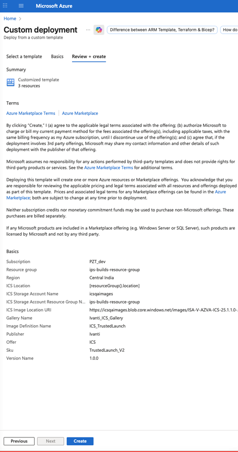
2.Click Create. Deployment will take 10 to 15 Minutes.
After a successful deployment, the Azure Gallery image for ICS will be ready for deploying the ICS virtual appliance.
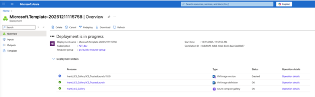
ICS Virtual Machine Deployment
1.Navigate to Custom Deployment.
2.Select Build your own template in the editor.
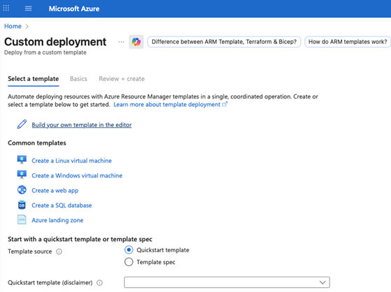
3.Download the Azure deployment template 2-NIC or 3-NIC from "Azure-template" folder (ivanticonnectsecure-3-nics/azuredeploy.json) to get azuredeploy.json.
ISA4000-V supports only 2-NIC deployment. ISA6000-V and ISA8000-V support 2-NIC and 3-NIC deployments.
|
Standard Model |
vCPU |
RAM(GiB) |
Disk Space |
NICs |
|---|---|---|---|---|
| ISA4000-V (Standard_D4s_v6) | 4 | 16 GB | 80 GB | 2 |
| ISA4000-V (Standard_D4ds_v6) | 4 | 16 GB | 80 GB | 2 |
| ISA6000-V (Standard_D8s_v6) | 8 | 32 GB | 80 GB | 3 |
|
ISA6000-V (Standard_D8ds_v6) |
8 | 32 GB | 80 GB | 3 |
|
ISA8000-V (Standard_D16ds_v6) |
16 |
64 GB |
80 GB |
3 |
|
ISA4000-V (Standard_F4as_v6) |
4 |
16 GB |
80 GB |
2 |
|
ISA6000-V (Standard_F8as_v6) |
8 | 32 GB | 80 GB | 3 |
|
ISA8000-V (Standard_F16as_v6) |
16 |
64 GB |
80 GB |
3 |
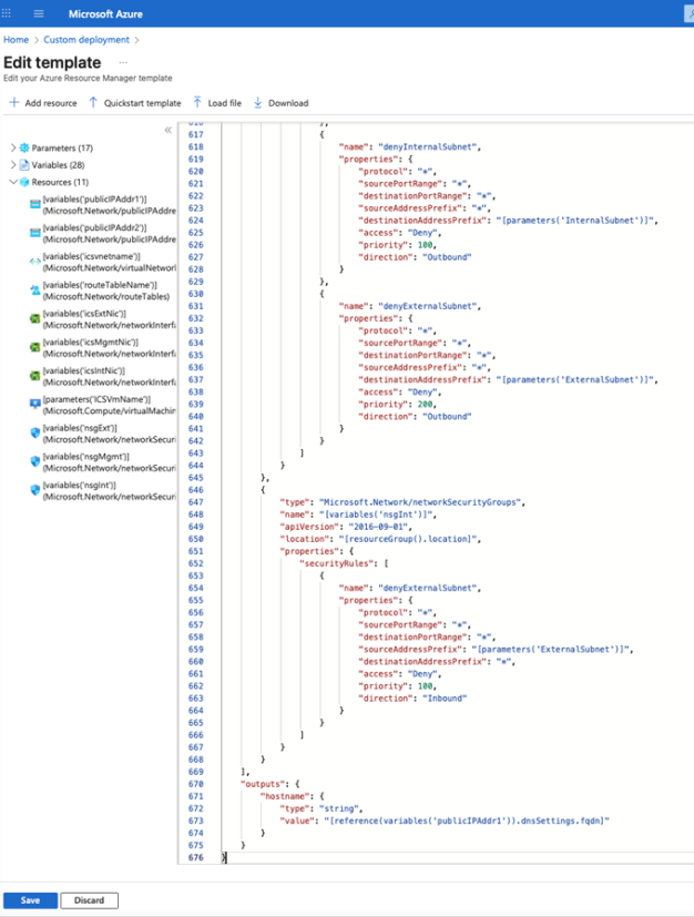
4.Copy and paste the azuredeploy.json into the designated field.
5.Edit Virtual Machine Standards - variables section "variables": ["VirtualMachineSize": "Standard_D8ds_v6",]
6.Click Save to apply the template.
You can modify the following parameters in the VM Template to suit your requirements:
•Gallery name, Image Definition name, and Image Version number
•Network Details
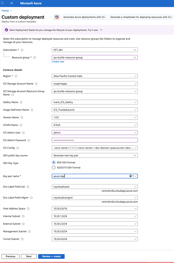
7.Fill or modify the following parameters:
•ICS Storage Account Name: Storage account name where ICS image is uploaded
•ICS Storage Account Resource Group Name: Resource group of the existing storage account where ICS image is uploaded
•Gallery Name: The name of the Shared Image Gallery (This value is from Azure gallery image created)
•Image Definition Name: The name of the Image Definition (This value is from Azure gallery image created)
•Version Name: The VM image version name in semantic version pattern. The allowed characters are digit and period. For example: 0.0.1, 15.35.0 (This value is from Azure gallery image created)
•ICS VM Name: This is the name given to ICS Virtual Appliance.
•ICS Admin User: Ivanti Connect Secure Admin User, value must be 2-30 characters long.
•ICS Admin Password: Ivanti Connect Secure Admin Password, value must be 12-128 characters long and no special characters.
•SSH Public Key: This is an RSA public key that is used to access Ivanti Connect Secure via SSH.
•ICS Config: This section contains provisioning parameters that are required during the deployment of a Virtual Appliance. An XML-based configuration file can be present in another Virtual Machine in Azure cloud or in the corporate network which is accessible for Ivanti Connect Secure through site-to-site VPN between Azure and the corporate data center.
•Key pair name: The new ssh key pair name.
•DNS Label Prefix Ext: This is the prefix for External Interface DNS label.
•DNS Label Prefix Mgmt: This is the prefix for Management Interface DNS label.
In case of two NIC deployment, the management port would not be auto-populated and admin has to provide details for internal port manually.
•VNet Address Space: This is a Virtual Network address space
•Internal Subnet: Subnet from which Ivanti Connect Secure Internal Interface needs to lease IP.
•External Subnet: Subnet from which Ivanti Connect Secure External Interface needs to lease IP.
•Management Subnet: Subnet from which Ivanti Connect Secure Management Interface needs to lease IP.
•Tunnel Subnet: Subnet which will be configured as Tunnel IP pool in Ivanti Connect Secure VPN profile.
8.Click Review + create to review your selections.
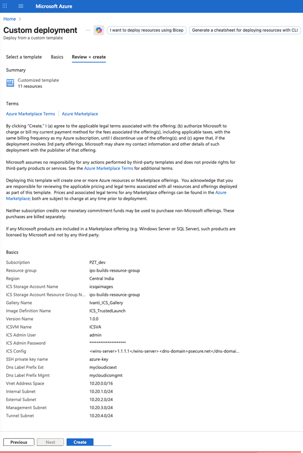
9.Click Create. A prompt will appear for generating new key pairs
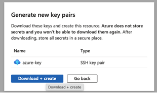
10.Click "Download + Create" to download the PEM key and begin deploying the virtual appliance (VA).
This action will create all required network resources, routes, and deploy the VA.
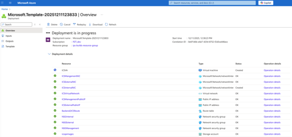
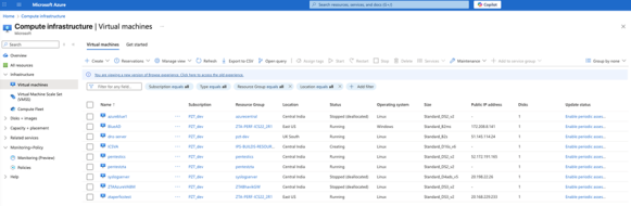
11. Once the virtual appliance (VA) status shows as "Created," the VA will appear in the list of Virtual Machines.
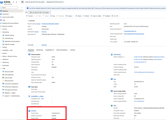
The new ICS virtual appliance will boot with the following features enabled:
•Secure Boot
•vTPM (virtual Trusted Platform Module)
•Disk controller type set to NVME
25.1.3.0 Release
•ISA VA Platforms for 25.1.3.0
•Deploying Ivanti Connect Secure Appliance on AWS
•Deploying Ivanti Connect Secure Appliance on GCP
ISA VA Platforms for 25.1.3.0
|
Platform |
Qualified |
Qualified Cloud VM Types /Equivalent ISA-V |
|---|---|---|
| Microsoft Hyper-V Server 2022 | Q | (4 vCPUs / ISA4500-v), (8 vCPUs/ ISA6500-v), (12 vCPUs/ ISA8500-v) |
| Azure | Q |
• ISA4500-V (Standard_D4ds_v6) • ISA4500-V (Standard_D4s_v6) • ISA6500-V (Standard_D8ds_v6) • ISA6500-V (Standard_D8s_v6) • ISA8500-V (Standard_D16ds_v6) • ISA4500-V (Standard_F4as_v6) • ISA6500-V (Standard_F8as_v6) • ISA8500-V (Standard_F16as_v6) |
| AWS | Q |
• ISA4500-V (c7i.xlarge) • ISA6500-V (c7i.2xlarge) • ISA8500-V (c7i.4xlarge) • ISA4500-V (m7i.xlarge) • ISA6500-V(m7i.2xlarge) • ISA8500-V (m7i.4xlarge) • ISA4500-V (c7i-flex.xlarge) • ISA6500-V (c7i-flex.2xlarge) • ISA8500-V (c7i-flex.4xlarge) • ISA4500-V (m7i-flex.xlarge) • ISA6500-V (m7i-flex.2xlarge) • ISA8500-V (m7i-flex.4xlarge) |
| GCP | Q |
• ISA4500-V (n4-standard-4) • ISA6500-V (n4-standard-8) • ISA8500-V (n4-standard-16) |
For the deployment details, see:
•VMware: Deploying Virtual ICS from OVF
•HyperV: Deploying Ivanti Connect Secure Appliance on Hyper-V
•Azure: Deploying Ivanti Connect Secure Appliance on Azure
In 25.1.3.0 release, the legacy SCSI storage subsystem is replaced with a high-performance NVMe (Non-Volatile Memory Express) controller on VMware.
Deploying Ivanti Connect Secure Appliance on AWS
Prerequisites
SNAT End Point Tunnel IP
The packets transmitted from ICS Internal Interface are dropped by AWS Virtual Gateway in L3 traffic. This is because the source IP and MAC address are not matching and the transit routing is not supported.
Ivanti Connect Secure must be able to SNAT these packets to the Internal interface IP which belongs to a subnet within the VPC.
To NAT endpoint tunnel IP to Internal interface IP, do the following:
1.Log in to Ivanti Connect Secure admin console.
2.Navigate to System > Network > VPN Tunneling.
3.Enable Source NATTING. By default, Source NATTING is disabled.

Enabling SNAT on ICS would reduce the number of connections, since one IP will be handling the traffic for all the end user Ivanti client connections. So, it is recommended that you purchase a NAT gateway and assign it to ICS.
Deploying Ivanti Connect Secure using AWS Marketplace
Ivanti Connect Secure is made available in AWS Market Place. The CloudFormation templates are available at Amazon marketplace.
Prerequisites and System Requirements on AWS Marketplace
To deploy the Ivanti Connect Secure Virtual Appliance on AWS Marketplace, you need the following:
•An AWS account
•Access to the AWS Marketplace (https://aws.amazon.com/marketplace)
•Ivanti Connect Secure licenses *
Deploying Ivanti Connect Secure on AWS Marketplace
4.Launch AWS Marketplace using the URL: https://aws.amazon.com/marketplace and search with keyword Ivanti.

AWS Marketplace contains the following two Ivanti Connect Secure SKUs:
•Ivanti Connect Secure - BYOL 2 NIC
•Ivanti Connect Secure - BYOL 3 NIC
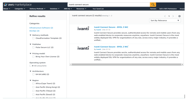

5.Select either 3-NIC model or 2-NIC model based on your requirement. In the Product Subscription page displayed, click Continue to Subscribe. In this section, 3-NIC model is chosen as example.
6.After subscribing, proceed to configuration by clicking Continue to Configuration.

7.In Fulfillment Option, select either Existing VPC or New VPC that you want to deploy and click Continue to Launch. In the Launch page displayed, select Launch CloudFormation and click Launch.
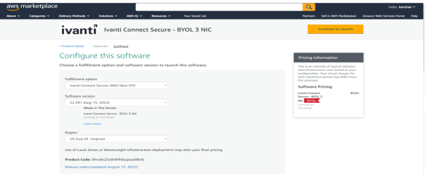
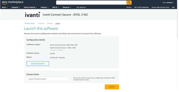
Specify Template
1.In the Create stack wizard, in the Specify Template page choose the template that describes your stack’s resources and their properties and, click Next.
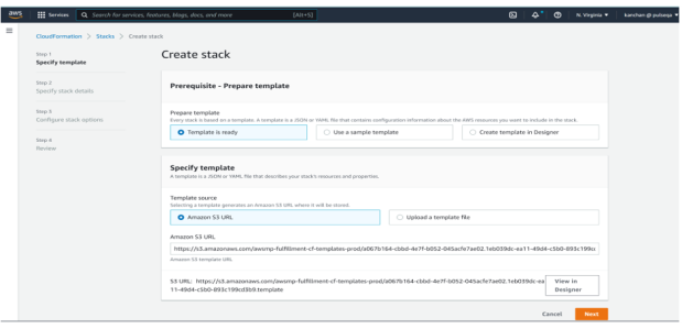
Specify Stack Details
1.In the Specify Stack Details page, specify a name for the stack.
2.In the Parameters section, use the default parameter values. These are defined in the CloudFormation template.
3.In the Ivanti Connect Secure Configuration section:
•Select Ivanti Connect Secure VM size. By default it is set to m5.xlarge.
•By default, ICS admin user name is configured. You can give any other user name if you want to.
•Enter the Admin user password.
•Config Data: This is pre-populated as part of AWS Cloudformation template. In order to customize the config parameters, see Ivanti Connect Secure Provisioning Parameters.
•Select SSH Key Name of EC2 key pair. This key is used to access ICS via SSH. The SSH keys are generated using ssh-keygen on Linux and OS X, or PuTTyGen on Windows. For details about generating the SSH key pairs, refer http://docs.aws.amazon.com/AWSEC2/latest/UserGuide/ec2-key-pairs.html.
Without providing the SSH key, an error is displayed during deployment.
Accessing the ICS using SSH will work on releases prior to 22.4R2 and all FIPS releases.
•In the Security Configuration section, enter Remote Access CIDR IP range that permits end user access to Ivanti Connect Secure instance.
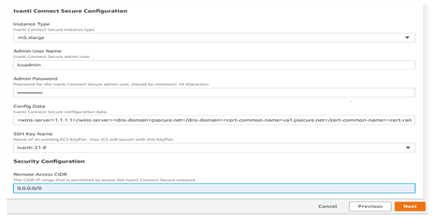
Review
1.In the Review page, verify the details and click Create.
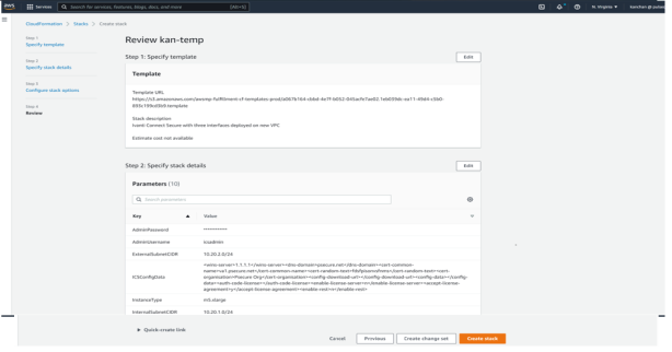
2.Wait for a few minutes while it creates all the resources. This completes deploying ICS on AWS Marketplace.

To access Ivanti Connect Secure Virtual Appliance, see Accessing the Ivanti Connect Secure Virtual Appliance
Resizing a Disk Volume in the AWS portal
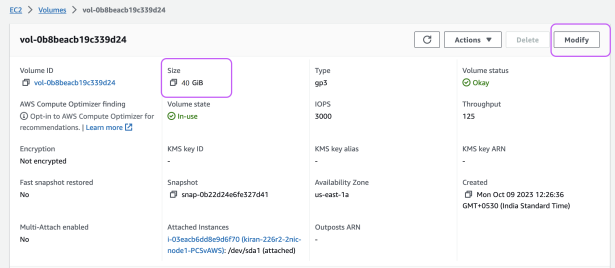
From 22.6R2 release, On fresh installation, 80 GB disk space is available by default. You can modify or increase the disk size only once on fresh installation or upgrade of the ICS images, but not on rollback or factory reset images.
If the user is upgrading to 22.6R2 or later, then the disk size change from 40 GB to 80 GB have to be done prior to upgrade on AWS cloud platform.
Disk Size Allocation is supported from 22.6R2 and later releases.
1.To increase the data volume size, in the navigation pane, choose Instances.
2.Under the Storage tab, select the Volume ID of your data volume.
3.Click Modify volume.
4.The Modify volume screen displays the volume ID and the volume’s current configuration, including type, size, input/output operations per second (IOPS), and throughput. Change the Size to 80 GB.
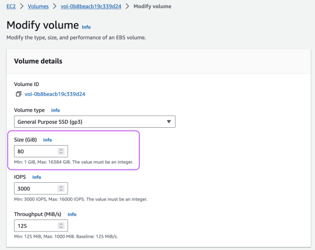
5.Choose Modify, and when prompted for confirmation choose Modify again. You are charged for the new volume configuration after volume modification starts.
Custom Ivanti Connect Secure Deployment on AWS Portal
Prerequisites and System Requirements on AWS
To deploy the Ivanti Connect Secure Virtual Appliance on AWS, you need the following:
•An AWS account
•Access to the AWS portal (https://console.aws.amazon.com/)*
•Ivanti Connect Secure Virtual Appliance AMI ID
•AWS CloudFormation template
•Ivanti Connect Secure licenses **
•Site-to-Site VPN between AWS and the corporate network (optional)
Note: This is needed only if the Ivanti Connect Secure users need to access corporate resources.
•Ivanti License Server (optional)**
•Located at corporate network, accessible through site-to-site VPN
•Ivanti Connect Secure configuration in XML format (optional)
Ivanti Connect Secure Virtual Appliance can be deployed only through AWS CloudFormation style.
Deploying Ivanti Connect Secure on Amazon Web Services
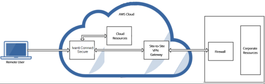
As depicted in the below diagram, a remote user can use Ivanti Connect Secure to securely access cloud resources as well as corporate resources. To access corporate resources, the Ivanti Connect Secure administrator needs to ensure that site-to-site VPN is already established between AWS and the corporate network.
Supported Platform Systems
From 25.1.3.0 release, ICS supports Secure Boot and Nitro TPM, and new instance types which are powered by 4th gen Intel Xenon Scalable processors and have support of DDR5 memory.
•ISA4500-V (xlarge)
•ISA6500-V (2xlarge)
•ISA8500-V (4xlarge)
|
Model |
vCPU |
Memory |
Diskspace |
|---|---|---|---|
| c7i.xlarge | 4 | 8 | 80 GB |
| c7i.2xlarge | 8 | 16 | 80 GB |
| c7i.4xlarge | 16 | 32 | 80 GB |
| m7i.xlarge | 4 | 16 | 80 GB |
|
m7i.2xlarge |
8 |
32 |
80 GB |
|
m7i.4xlarge |
16 |
64 |
80 GB |
|
c7i-flex.xlarge |
4 |
8 |
80 GB |
|
c7i-flex.2xlarge |
8 |
16 |
80 GB |
|
c7i-flex.4xlarge |
16 |
32 |
80 GB |
|
m7i-flex.xlarge |
4 |
16 |
80 GB |
|
m7i-flex.2xlarge |
8 |
32 |
80 GB |
|
m7i-flex.4xlarge |
16 |
64 |
80 GB |
Customs Templates
To deploy 2-NIC or 3-NIC in an existing VPC respectively using the links below:
Ivanti-2nic-existing-vpc.json
{
"AWSTemplateFormatVersion" : "2010-09-09",
"Description" : "Deploy ICS with 2 nic into an existing VPC",
"Metadata" : {
"AWS::CloudFormation::Interface" : {
"ParameterGroups" : [
{
"Label" : { "default" : "Existing VPC details" },
"Parameters" : [ "VpcId", "SubnetIntId", "SubnetExtId"]
},
{
"Label" : { "default":"ICS Configuration" },
"Parameters" : [
"InstanceType",
"AdminUsername",
"AdminPassword",
"ICSConfigData",
"ICSImageAMIId",
"KeyName" ]
}
],
"ParameterLabels" : {
"VpcId" : { "default" : "Existing VPC ID" },
"SubnetIntId" : {"default" : "Internal Subnet ID"},
"SubnetExtId" : {"default" : "External Subnet ID"},
"ICSImageAMIId" : {"default" : "ICS AMI ID"},
"InstanceType" : {"default" : "Instance Type"},
"KeyName" : {"default" : "SSH Key Name"},
"AdminUsername": {"default": "Admin User Name"},
"AdminPassword": {"default": "Admin Password"},
"ICSConfigData": {"default": "Config Data"}
}
}
},
"Parameters" : {
"KeyName": {
"Type": "AWS::EC2::KeyPair::KeyName",
"Default": "",
"AllowedPattern" : "[-_ a-zA-Z0-9]*",
"Description": "Name of an existing EC2 KeyPair. Your ICS will launch with this KeyPair.",
"ConstraintDescription": "Must be the name of an existing EC2 KeyPair."
},
"ICSImageAMIId" : {
"Type" : "String",
"Description" : "AMI ID of your existing ICS image"
},
"InstanceType": {
"Description": "Select ICS instance type",
"Type": "String",
"Default": "c7i.xlarge",
"AllowedValues": [
"c7i.xlarge",
"c7i.2xlarge",
"c7i.4xlarge",
"m7i.xlarge",
"m7i.2xlarge",
"m7i.4xlarge",
"c7i-flex.xlarge",
"c7i-flex.2xlarge",
"c7i-flex.4xlarge",
"m7i-flex.xlarge",
"m7i-flex.2xlarge",
"m7i-flex.4xlarge"
],
"ConstraintDescription": "Must be an allowed EC2 instance type."
},
"AdminUsername": {
"Description": "Ivanti Connect Secure admin user.",
"Type": "String",
"MinLength": "1",
"MaxLength": "30",
"AllowedPattern": ".{1,30}"
},
"AdminPassword": {
"Description": "Password for the Ivanti Connect Secure admin user, should be minimum 10 characters",
"Type": "String",
"MinLength": "10",
"MaxLength": "128",
"AllowedPattern": ".{10,128}",
"NoEcho": "true"
},
"ICSConfigData": {
"Type": "String",
"Description": "Ivanti Connect Secure configuration data.",
"Default": "<wins-server>1.1.1.1</wins-server><dns-domain>psecure.net</dns-domain><cert-common-name>va1.psecure.net</cert-common-name><cert-random-text>fdsfpisonvsfnms</cert-random-text><cert-organisation>Psecure Org</cert-organisation><config-download-url></config-download-url><config-data></config-data><auth-code-license></auth-code-license><enable-license-server>n</enable-license-server><accept-license-agreement>y</accept-license-agreement>",
"AllowedPattern": "^<wins-server>(([2][5][0-5]\\.)|([2][0-4][0-9]\\.)|([0-1]?[0-9]?[0-9]\\.)){3}(([2][5][0-5])|([2][0-4][0-9])|([0-1]?[0-9]?[0-9]))</wins-server><dns-domain>.{1,50}</dns-domain><cert-common-name>.{1,50}</cert-common-name><cert-random-text>.{1,50}</cert-random-text><cert-organisation>.{1,80}</cert-organisation><config-download-url>.*</config-download-url><config-data>.*</config-data><auth-code-license>.*</auth-code-license><enable-license-server>[yn]</enable-license-server><accept-license-agreement>[yn]</accept-license-agreement>$",
"ConstraintDescription": "Invalid configuration. Please refer Ivanti Connect Secure AWS deployment guide for configuration elements and allowed values."
},
"VpcId" : {
"Type" : "String",
"Description" : "ID of existing VPC"
},
"SubnetIntId" : {
"Type" : "String",
"Description" : "ID of the subnet where ICS internal interface connects"
},
"SubnetExtId" : {
"Type" : "String",
"Description" : "ID of the subnet where ICS External interface connects"
}
},
"Resources" : {
"EIP0" : {
"Type" : "AWS::EC2::EIP",
"Properties" : {
"Domain" : "vpc"
}
},
"EIPAssoc0" : {
"Type" : "AWS::EC2::EIPAssociation",
"Properties" : {
"NetworkInterfaceId" : { "Ref" : "Eth0" },
"AllocationId" : { "Fn::GetAtt" : ["EIP0", "AllocationId"] },
"PrivateIpAddress" : { "Fn::GetAtt" : ["Eth0", "PrimaryPrivateIpAddress" ] }
}
},
"EIP1" : {
"Type" : "AWS::EC2::EIP",
"Properties" : {
"Domain" : "vpc"
}
},
"EIPAssoc1" : {
"Type" : "AWS::EC2::EIPAssociation",
"Properties" : {
"NetworkInterfaceId" : { "Ref" : "Eth1" },
"AllocationId" : { "Fn::GetAtt" : ["EIP1", "AllocationId"] },
"PrivateIpAddress" : { "Fn::GetAtt" : ["Eth1", "PrimaryPrivateIpAddress" ] }
}
},
"ICSvExternalSecurityGroup": {
"Type": "AWS::EC2::SecurityGroup",
"Properties": {
"GroupDescription": "Access Rules for ICS external port",
"VpcId": {
"Ref": "VpcId"
},
"SecurityGroupIngress": [
{
"IpProtocol": "icmp",
"FromPort": "-1",
"ToPort": "-1",
"CidrIp": "0.0.0.0/0"
},
{
"IpProtocol": "tcp",
"FromPort": "80",
"ToPort": "80",
"CidrIp": "0.0.0.0/0"
},
{
"IpProtocol": "tcp",
"FromPort": "443",
"ToPort": "443",
"CidrIp": "0.0.0.0/0"
},
{
"IpProtocol": "udp",
"FromPort": "4500",
"ToPort": "4500",
"CidrIp": "0.0.0.0/0"
},
{
"IpProtocol": "tcp",
"FromPort": "11000",
"ToPort": "11099",
"CidrIp": "0.0.0.0/0"
}
],
"SecurityGroupEgress": [
{
"CidrIp": "127.0.0.1/32",
"IpProtocol": "-1"
}],
"Tags": [
{
"Key": "Name",
"Value": { "Fn::Join": [ "-", [ { "Ref": "AWS::StackName" }, "ICSvExtSG" ] ] }
}
]
}
},
"ICSvInternalSecurityGroup": {
"Type": "AWS::EC2::SecurityGroup",
"Properties": {
"GroupDescription": "Access Rules for ICS internal port",
"VpcId": {
"Ref": "VpcId"
},
"SecurityGroupIngress": [
{
"IpProtocol": "icmp",
"FromPort": "-1",
"ToPort": "-1",
"CidrIp": "0.0.0.0/0"
},
{
"IpProtocol": "tcp",
"FromPort": "80",
"ToPort": "80",
"CidrIp": "0.0.0.0/0"
},
{
"IpProtocol": "tcp",
"FromPort": "443",
"ToPort": "443",
"CidrIp": "0.0.0.0/0"
}
],
"Tags": [
{
"Key": "Name",
"Value": { "Fn::Join": [ "-", [ { "Ref": "AWS::StackName" }, "ICSvIntSG" ] ] }
}
]
}
},
"EC2Instance" : {
"Type" : "AWS::EC2::Instance",
"DependsOn" : ["EIPAssoc0", "EIPAssoc1"],
"Properties" : {
"ImageId" : {"Ref" : "ICSImageAMIId"},
"KeyName" : { "Ref" : "KeyName" },
"InstanceType" : { "Ref" : "InstanceType" },
"NetworkInterfaces" : [
{ "NetworkInterfaceId" : {"Ref" : "Eth0" }, "DeviceIndex" : "0" },
{ "NetworkInterfaceId" : {"Ref" : "Eth1" }, "DeviceIndex" : "1" }
],
"Tags" : [
{"Key" : "Name",
"Value" : { "Fn::Join": [ "-", [ { "Ref": "AWS::StackName" }, "ICSvAWS" ] ] }
}
],
"UserData": {
"Fn::Base64": {
"Fn::Join": [
"",
[
"<pulse-config>",
"<admin-password>",
{
"Ref": "AdminPassword"
},
"</admin-password>",
"<admin-username>",
{
"Ref": "AdminUsername"
},
"</admin-username>",
{
"Ref": "ICSConfigData"
},
"</pulse-config>"
]
]
}
},
"MetadataOptions": {
"HttpTokens": "required",
"HttpPutResponseHopLimit": 1
}
}
},
"Eth0" : {
"Type" : "AWS::EC2::NetworkInterface",
"Properties" : {
"Description" : "eth0",
"GroupSet" : [ { "Ref" : "ICSvInternalSecurityGroup" } ],
"SourceDestCheck" : "false",
"SubnetId" : { "Ref" : "SubnetIntId" },
"Tags" : [ {"Key" : "Name", "Value" : "Interface 0"}, {"Key" : "Interface", "Value" : "eth0"} ]
}
},
"Eth1" : {
"Type" : "AWS::EC2::NetworkInterface",
"Properties" : {
"Description" : "eth1",
"GroupSet" : [ { "Ref" : "ICSvExternalSecurityGroup" } ],
"SourceDestCheck" : "false",
"SubnetId" : { "Ref" : "SubnetExtId" },
"Tags" : [ {"Key" : "Name", "Value" : "Interface 1"}, {"Key" : "Interface", "Value" : "eth1"} ]
}
}
},
"Outputs" : {
"InstanceId" : {
"Value" : { "Ref" : "EC2Instance" },
"Description" : "Instance Id of newly created instance"
},
"ExternalAddress" : {
"Value" : { "Fn::Join" : [" ", [ "Public IP address:", { "Ref" : "EIP1" }, "Private IP address:", { "Fn::GetAtt" : ["Eth1", "PrimaryPrivateIpAddress"] }]]},
"Description" : "ICS Extenal Interface details"
},
"InternalAddress" : {
"Value" : { "Fn::Join" : [" ", [ "Public IP address:", { "Ref" : "EIP0" }, "Private IP address:", { "Fn::GetAtt" : ["Eth0", "PrimaryPrivateIpAddress"] }]]},
"Description" : "ICS Internal Interface details"
}
}
}
{
"AWSTemplateFormatVersion" : "2010-09-09",
"Description" : "Deploy ICS with 3 nic into an existing VPC",
"Metadata" : {
"AWS::CloudFormation::Interface" : {
"ParameterGroups" : [
{
"Label" : { "default" : "Existing VPC details" },
"Parameters" : [ "VpcId", "SubnetIntId", "SubnetExtId", "SubnetMgmtId" ]
},
{
"Label" : { "default":"ICS Configuration" },
"Parameters" : [
"ICSImageAMIId",
"InstanceType",
"AdminUsername",
"AdminPassword",
"ICSConfigData",
"KeyName" ]
}
],
"ParameterLabels" : {
"VpcId" : { "default" : "Existing VPC ID" },
"SubnetIntId" : {"default" : "Internal Subnet ID"},
"SubnetExtId" : {"default" : "External Subnet ID"},
"SubnetMgmtId" : {"default" : "Management Subnet ID"},
"ICSImageAMIId" : {"default" : "ICS AMI ID"},
"InstanceType" : {"default" : "Instance Type"},
"KeyName" : {"default" : "SSH Key Name"},
"AdminUsername": {"default": "Admin User Name"},
"AdminPassword": {"default": "Admin Password"},
"ICSConfigData": {"default": "Config Data"}
}
}
},
"Parameters" : {
"KeyName": {
"Type": "AWS::EC2::KeyPair::KeyName",
"AllowedPattern" : "[-_ a-zA-Z0-9]*",
"Description": "Name of an existing EC2 KeyPair. Your ICS will launch with this KeyPair.",
"ConstraintDescription": "Must be the name of an existing EC2 KeyPair."
},
"ICSImageAMIId" : {
"Type" : "String",
"Description" : "AMI ID of your existing ICS image"
},
"InstanceType": {
"Description": "Select ICS instance type",
"Type": "String",
"Default": "c7i.xlarge",
"AllowedValues": [
"c7i.xlarge",
"c7i.2xlarge",
"c7i.4xlarge",
"m7i.xlarge",
"m7i.2xlarge",
"m7i.4xlarge",
"c7i-flex.xlarge",
"c7i-flex.2xlarge",
"c7i-flex.4xlarge",
"m7i-flex.xlarge",
"m7i-flex.2xlarge",
"m7i-flex.4xlarge"
],
"ConstraintDescription": "Must be an allowed EC2 instance type."
},
"AdminUsername": {
"Description": "Ivanti Connect Secure admin user.",
"Type": "String",
"MinLength": "1",
"MaxLength": "30",
"AllowedPattern": ".{1,30}"
},
"AdminPassword": {
"Description": "Password for the Ivanti Connect Secure admin user, should be minimum 10 characters",
"Type": "String",
"MinLength": "10",
"MaxLength": "128",
"AllowedPattern": ".{10,128}",
"NoEcho": "true"
},
"ICSConfigData": {
"Type": "String",
"Description": "Ivanti Connect Secure configuration data.",
"Default": "<wins-server>1.1.1.1</wins-server><dns-domain>psecure.net</dns-domain><cert-common-name>va1.psecure.net</cert-common-name><cert-random-text>fdsfpisonvsfnms</cert-random-text><cert-organisation>Psecure Org</cert-organisation><config-download-url></config-download-url><config-data></config-data><auth-code-license></auth-code-license><enable-license-server>n</enable-license-server><accept-license-agreement>y</accept-license-agreement>",
"AllowedPattern": "^<wins-server>(([2][5][0-5]\\.)|([2][0-4][0-9]\\.)|([0-1]?[0-9]?[0-9]\\.)){3}(([2][5][0-5])|([2][0-4][0-9])|([0-1]?[0-9]?[0-9]))</wins-server><dns-domain>.{1,50}</dns-domain><cert-common-name>.{1,50}</cert-common-name><cert-random-text>.{1,50}</cert-random-text><cert-organisation>.{1,80}</cert-organisation><config-download-url>.*</config-download-url><config-data>.*</config-data><auth-code-license>.*</auth-code-license><enable-license-server>[yn]</enable-license-server><accept-license-agreement>[yn]</accept-license-agreement>$",
"ConstraintDescription": "Invalid configuration. Please refer Ivanti Connect Secure AWS deployment guide for configuration elements and allowed values."
},
"VpcId" : {
"Type" : "String",
"Description" : "ID of existing VPC"
},
"SubnetIntId" : {
"Type" : "String",
"Description" : "ID of the subnet where ICS internal interface connects"
},
"SubnetExtId" : {
"Type" : "String",
"Description" : "ID of the subnet where ICS External interface connects"
},
"SubnetMgmtId" : {
"Type" : "String",
"Description" : "ID of the subnet where ICS Management interface connects"
}
},
"Resources" : {
"EIP0" : {
"Type" : "AWS::EC2::EIP",
"Properties" : {
"Domain" : "vpc"
}
},
"EIPAssoc0" : {
"Type" : "AWS::EC2::EIPAssociation",
"Properties" : {
"NetworkInterfaceId" : { "Ref" : "Eth0" },
"AllocationId" : { "Fn::GetAtt" : ["EIP0", "AllocationId"] },
"PrivateIpAddress" : { "Fn::GetAtt" : ["Eth0", "PrimaryPrivateIpAddress" ] }
}
},
"EIP1" : {
"Type" : "AWS::EC2::EIP",
"Properties" : {
"Domain" : "vpc"
}
},
"EIPAssoc1" : {
"Type" : "AWS::EC2::EIPAssociation",
"Properties" : {
"NetworkInterfaceId" : { "Ref" : "Eth1" },
"AllocationId" : { "Fn::GetAtt" : ["EIP1", "AllocationId"] },
"PrivateIpAddress" : { "Fn::GetAtt" : ["Eth1", "PrimaryPrivateIpAddress" ] }
}
},
"EIP2" : {
"Type" : "AWS::EC2::EIP",
"Properties" : {
"Domain" : "vpc"
}
},
"EIPAssoc2" : {
"Type" : "AWS::EC2::EIPAssociation",
"Properties" : {
"NetworkInterfaceId" : { "Ref" : "Eth2" },
"AllocationId" : { "Fn::GetAtt" : ["EIP2", "AllocationId"] },
"PrivateIpAddress" : { "Fn::GetAtt" : ["Eth2", "PrimaryPrivateIpAddress" ] }
}
},
"ICSvExternalSecurityGroup": {
"Type": "AWS::EC2::SecurityGroup",
"Properties": {
"GroupDescription": "Access Rules for ICS external port",
"VpcId": {
"Ref": "VpcId"
},
"SecurityGroupIngress": [
{
"IpProtocol": "icmp",
"FromPort": "-1",
"ToPort": "-1",
"CidrIp": "0.0.0.0/0"
},
{
"IpProtocol": "tcp",
"FromPort": "80",
"ToPort": "80",
"CidrIp": "0.0.0.0/0"
},
{
"IpProtocol": "tcp",
"FromPort": "443",
"ToPort": "443",
"CidrIp": "0.0.0.0/0"
},
{
"IpProtocol": "udp",
"FromPort": "4500",
"ToPort": "4500",
"CidrIp": "0.0.0.0/0"
},
{
"IpProtocol": "tcp",
"FromPort": "11000",
"ToPort": "11099",
"CidrIp": "0.0.0.0/0"
}
],
"SecurityGroupEgress": [
{
"CidrIp": "127.0.0.1/32",
"IpProtocol": "-1"
}],
"Tags": [
{
"Key": "Name",
"Value": { "Fn::Join": [ "-", [ { "Ref": "AWS::StackName" }, "ICSvExtSG" ] ] }
}
]
}
},
"ICSvInternalSecurityGroup": {
"Type": "AWS::EC2::SecurityGroup",
"Properties": {
"GroupDescription": "Access Rules for ICS internal port",
"VpcId": {
"Ref": "VpcId"
},
"SecurityGroupIngress": [
{
"IpProtocol": "icmp",
"FromPort": "-1",
"ToPort": "-1",
"CidrIp": "0.0.0.0/0"
}
],
"Tags": [
{
"Key": "Name",
"Value": { "Fn::Join": [ "-", [ { "Ref": "AWS::StackName" }, "ICSvIntSG" ] ] }
}
]
}
},
"ICSvManagementSecurityGroup": {
"Type": "AWS::EC2::SecurityGroup",
"Properties": {
"GroupDescription": "Access Rules for ICS Management port",
"VpcId": {
"Ref": "VpcId"
},
"SecurityGroupIngress": [
{
"IpProtocol": "icmp",
"FromPort": "-1",
"ToPort": "-1",
"CidrIp": "0.0.0.0/0"
},
{
"IpProtocol": "tcp",
"FromPort": "80",
"ToPort": "80",
"CidrIp": "0.0.0.0/0"
},
{
"IpProtocol": "tcp",
"FromPort": "443",
"ToPort": "443",
"CidrIp": "0.0.0.0/0"
}
],
"SecurityGroupEgress": [
{
"CidrIp": "127.0.0.1/32",
"IpProtocol": "-1"
}],
"Tags": [
{
"Key": "Name",
"Value": { "Fn::Join": [ "-", [ { "Ref": "AWS::StackName" }, "ICSvMgmtSG" ] ] }
}
]
}
},
"EC2Instance" : {
"Type" : "AWS::EC2::Instance",
"DependsOn" : ["EIPAssoc0", "EIPAssoc1", "EIPAssoc2"],
"Properties" : {
"ImageId" : {"Ref" : "ICSImageAMIId"},
"KeyName" : { "Ref" : "KeyName" },
"InstanceType" : { "Ref" : "InstanceType" },
"NetworkInterfaces" : [
{ "NetworkInterfaceId" : {"Ref" : "Eth0" }, "DeviceIndex" : "0" },
{ "NetworkInterfaceId" : {"Ref" : "Eth1" }, "DeviceIndex" : "1" },
{ "NetworkInterfaceId" : {"Ref" : "Eth2" }, "DeviceIndex" : "2" }
],
"Tags" : [
{"Key" : "Name",
"Value" : { "Fn::Join": [ "-", [ { "Ref": "AWS::StackName" }, "ICSvAWS" ] ] }
}
],
"UserData": {
"Fn::Base64": {
"Fn::Join": [
"",
[
"<pulse-config>",
"<admin-password>",
{
"Ref": "AdminPassword"
},
"</admin-password>",
"<admin-username>",
{
"Ref": "AdminUsername"
},
"</admin-username>",
{
"Ref": "ICSConfigData"
},
"</pulse-config>"
]
]
}
},
"MetadataOptions": {
"HttpTokens": "required",
"HttpPutResponseHopLimit": 1
}
}
},
"Eth0" : {
"Type" : "AWS::EC2::NetworkInterface",
"Properties" : {
"Description" : "eth0",
"GroupSet" : [ { "Ref" : "ICSvInternalSecurityGroup" } ],
"SourceDestCheck" : "false",
"SubnetId" : { "Ref" : "SubnetIntId" },
"Tags" : [ {"Key" : "Name", "Value" : "Interface 0"}, {"Key" : "Interface", "Value" : "eth0"} ]
}
},
"Eth1" : {
"Type" : "AWS::EC2::NetworkInterface",
"Properties" : {
"Description" : "eth1",
"GroupSet" : [ { "Ref" : "ICSvExternalSecurityGroup" } ],
"SourceDestCheck" : "false",
"SubnetId" : { "Ref" : "SubnetExtId" },
"Tags" : [ {"Key" : "Name", "Value" : "Interface 1"}, {"Key" : "Interface", "Value" : "eth1"} ]
}
},
"Eth2" : {
"Type" : "AWS::EC2::NetworkInterface",
"Properties" : {
"Description" : "eth2",
"GroupSet" : [ { "Ref" : "ICSvManagementSecurityGroup" } ],
"SourceDestCheck" : "false",
"SubnetId" : { "Ref" : "SubnetMgmtId" },
"Tags" : [ {"Key" : "Name", "Value" : "Interface 2"}, {"Key" : "Interface", "Value" : "eth2"} ]
}
}
},
"Outputs" : {
"InstanceId" : {
"Value" : { "Ref" : "EC2Instance" },
"Description" : "Instance Id of newly created instance"
},
"ManagementAddress" : {
"Value" : { "Fn::Join" : [" ", [ "Public IP address:", { "Ref" : "EIP2" }, "Private IP address:", { "Fn::GetAtt" : ["Eth2", "PrimaryPrivateIpAddress"] }]]},
"Description" : "ICS Management Interface details"
},
"ExternalAddress" : {
"Value" : { "Fn::Join" : [" ", [ "Public IP address:", { "Ref" : "EIP1" }, "Private IP address:", { "Fn::GetAtt" : ["Eth1", "PrimaryPrivateIpAddress"] }]]},
"Description" : "ICS External Interface details"
},
"InternalAddress" : {
"Value" : { "Fn::Join" : [" ", [ "Public IP address:", { "Ref" : "EIP0" }, "Private IP address:", { "Fn::GetAtt" : ["Eth0", "PrimaryPrivateIpAddress"] }]]},
"Description" : "ICS Internal Interface details"
}
}
}
To deploy 2-NIC or 3-NIC in a new VPC respectively using the links below:
Ivanti-2nic-new-vpc.json
{
"AWSTemplateFormatVersion" : "2010-09-09",
"Description" : "Deploy ICS with 2 nic into a new VPC",
"Metadata" : {
"AWS::CloudFormation::Interface" : {
"ParameterGroups" : [
{
"Label" : { "default" : "New VPC Configuration" },
"Parameters" : [ "VPCCIDR", "InternalSubnetCIDR", "ExternalSubnetCIDR", "TunnelSubnetCIDR" ]
},
{
"Label" : { "default":"ICS Configuration" },
"Parameters" : [
"InstanceType",
"AdminUsername",
"AdminPassword",
"ICSConfigData",
"ICSImageAMIId",
"KeyName"
]
}
],
"ParameterLabels" : {
"VPCCIDR" : { "default" : "New VPC address space" },
"InternalSubnetCIDR" : {"default" : "Internal Subnet address space"},
"ExternalSubnetCIDR" : {"default" : "External Subnet address space"},
"TunnelSubnetCIDR" : {"default" : "Tunnel Subnet address space"},
"ICSImageAMIId" : {"default" : "ICS AMI ID"},
"InstanceType" : {"default" : "Instance Type"},
"KeyName" : {"default" : "SSH Key Name"},
"AdminUsername": {"default": "Admin User Name"},
"AdminPassword": {"default": "Admin Password"},
"ICSConfigData": {"default": "Config Data"}
}
}
},
"Parameters" : {
"KeyName": {
"Type": "AWS::EC2::KeyPair::KeyName",
"Default": "",
"AllowedPattern" : "[-_ a-zA-Z0-9]*",
"Description": "Name of an existing EC2 KeyPair. Your ICS will launch with this KeyPair.",
"ConstraintDescription": "Must be the name of an existing EC2 KeyPair."
},
"ICSImageAMIId" : {
"Type" : "String",
"Description" : "AMI ID of your existing ICS image"
},
"InstanceType": {
"Description": "Select ICS instance type",
"Type": "String",
"Default": "m7i-flex.xlarge",
"AllowedValues": [
"m7i-flex.xlarge",
"m7i-flex.2xlarge",
"m7i-flex.4xlarge",
"m7i.xlarge",
"m7i.2xlarge",
"m7i.4xlarge",
"c7i-flex.xlarge",
"c7i-flex.2xlarge",
"c7i-flex.4xlarge",
"c7i.xlarge",
"c7i.2xlarge",
"c7i.4xlarge"
],
"ConstraintDescription": "Must be an allowed EC2 instance type."
},
"AdminUsername": {
"Description": "Ivanti Connect Secure admin user.",
"Type": "String",
"MinLength": "1",
"MaxLength": "30",
"AllowedPattern": ".{1,30}"
},
"AdminPassword": {
"Description": "Password for the Ivanti Connect Secure admin user, should be minimum 10 characters",
"Type": "String",
"MinLength": "10",
"MaxLength": "128",
"AllowedPattern": ".{10,128}",
"NoEcho": "true"
},
"ICSConfigData": {
"Type": "String",
"Description": "Ivanti Connect Secure configuration data.",
"Default": "<wins-server>1.1.1.1</wins-server><dns-domain>psecure.net</dns-domain><cert-common-name>va1.psecure.net</cert-common-name><cert-random-text>fdsfpisonvsfnms</cert-random-text><cert-organisation>Psecure Org</cert-organisation><config-download-url></config-download-url><config-data></config-data><auth-code-license></auth-code-license><enable-license-server>n</enable-license-server><accept-license-agreement>y</accept-license-agreement>",
"AllowedPattern": "^<wins-server>(([2][5][0-5]\\.)|([2][0-4][0-9]\\.)|([0-1]?[0-9]?[0-9]\\.)){3}(([2][5][0-5])|([2][0-4][0-9])|([0-1]?[0-9]?[0-9]))</wins-server><dns-domain>.{1,50}</dns-domain><cert-common-name>.{1,50}</cert-common-name><cert-random-text>.{1,50}</cert-random-text><cert-organisation>.{1,80}</cert-organisation><config-download-url>.*</config-download-url><config-data>.*</config-data><auth-code-license>.*</auth-code-license><enable-license-server>[yn]</enable-license-server><accept-license-agreement>[yn]</accept-license-agreement>$",
"ConstraintDescription": "Invalid configuration. Please refer Ivanti Connect Secure AWS deployment guide for configuration elements and allowed values."
},
"VPCCIDR": {
"Description": "CIDR block for entire VPC.",
"Type": "String",
"Default": "10.20.0.0/16",
"AllowedPattern": "^(([0-9]|[1-9][0-9]|1[0-9]{2}|2[0-4][0-9]|25[0-5])\\.){3}([0-9]|[1-9][0-9]|1[0-9]{2}|2[0-4][0-9]|25[0-5])(\\/([0-9]|[1-2][0-9]|3[0-2]))$",
"ConstraintDescription": "Must be a valid CIDR range of the form x.x.x.x/x."
},
"InternalSubnetCIDR": {
"Description": "ICS internal interface connects to this subnet",
"Type": "String",
"Default": "10.20.1.0/24",
"AllowedPattern": "^(([0-9]|[1-9][0-9]|1[0-9]{2}|2[0-4][0-9]|25[0-5])\\.){3}([0-9]|[1-9][0-9]|1[0-9]{2}|2[0-4][0-9]|25[0-5])(\\/([0-9]|[1-2][0-9]|3[0-2]))$",
"ConstraintDescription": "CIDR block parameter must be in the form x.x.x.x/x"
},
"ExternalSubnetCIDR": {
"Description": "ICS external interface connects to this subnet",
"Type": "String",
"Default": "10.20.2.0/24",
"AllowedPattern": "^(([0-9]|[1-9][0-9]|1[0-9]{2}|2[0-4][0-9]|25[0-5])\\.){3}([0-9]|[1-9][0-9]|1[0-9]{2}|2[0-4][0-9]|25[0-5])(\\/([0-9]|[1-2][0-9]|3[0-2]))$",
"ConstraintDescription": "CIDR block parameter must be in the form x.x.x.x/x"
},
"TunnelSubnetCIDR": {
"Description": "For L3 VPN connections ICS hands over IP to the clients from this subnet",
"Type": "String",
"Default": "10.20.3.0/24",
"AllowedPattern": "^(([0-9]|[1-9][0-9]|1[0-9]{2}|2[0-4][0-9]|25[0-5])\\.){3}([0-9]|[1-9][0-9]|1[0-9]{2}|2[0-4][0-9]|25[0-5])(\\/([0-9]|[1-2][0-9]|3[0-2]))$",
"ConstraintDescription": "CIDR block parameter must be in the form x.x.x.x/x"
}
},
"Resources" : {
"VPC" : {
"Type" : "AWS::EC2::VPC",
"Properties" : {
"CidrBlock" : {"Ref": "VPCCIDR"},
"EnableDnsHostnames": "true",
"EnableDnsSupport": "true",
"Tags" : [ {"Key" : "Application", "Value" : { "Ref" : "AWS::StackId"} },
{"Key" : "Name", "Value" : { "Fn::Join": [ "-", [ { "Ref": "AWS::StackName" }, "ICSVPC" ] ] } }
]
}
},
"IntSubnet" : {
"Type" : "AWS::EC2::Subnet",
"Properties" : {
"VpcId" : { "Ref" : "VPC" },
"CidrBlock" : {"Ref" : "InternalSubnetCIDR"},
"AvailabilityZone" : {
"Fn::Select" : [ "0", { "Fn::GetAZs" : "" } ]
},
"Tags" : [ {"Key" : "Application", "Value" : { "Ref" : "AWS::StackId"} },
{"Key" : "Name", "Value" : { "Fn::Join": [ "-", [ { "Ref": "AWS::StackName" }, "ICSVPCIntSubnet" ] ] } }
]
}
},
"ExtSubnet" : {
"Type" : "AWS::EC2::Subnet",
"Properties" : {
"VpcId" : { "Ref" : "VPC" },
"CidrBlock" : {"Ref" : "ExternalSubnetCIDR"},
"AvailabilityZone" : {
"Fn::Select" : [ "0", { "Fn::GetAZs" : "" } ]
},
"Tags" : [ {"Key" : "Application", "Value" : { "Ref" : "AWS::StackId"} },
{"Key" : "Name", "Value" : { "Fn::Join": [ "-", [ { "Ref": "AWS::StackName" }, "ICSVPCExtSubnet" ] ] } }
]
}
},
"TunnelSubnet" : {
"Type" : "AWS::EC2::Subnet",
"Properties" : {
"VpcId" : { "Ref" : "VPC" },
"CidrBlock" : {"Ref" : "TunnelSubnetCIDR"},
"AvailabilityZone" : {
"Fn::Select" : [ "0", { "Fn::GetAZs" : "" } ]
},
"Tags" : [ {"Key" : "Application", "Value" : { "Ref" : "AWS::StackId"} },
{"Key" : "Name", "Value" : { "Fn::Join": [ "-", [ { "Ref": "AWS::StackName" }, "ICSVPCTunnelSubnet" ] ] } }
]
}
},
"InternetGateway" : {
"Type" : "AWS::EC2::InternetGateway",
"Properties" : {
"Tags" : [ {"Key" : "Application", "Value" : { "Ref" : "AWS::StackId"} },
{"Key" : "Name", "Value" : { "Fn::Join": [ "-", [ { "Ref": "AWS::StackName" }, "ICSVPC" ] ] } }
]
}
},
"AttachGateway" : {
"Type" : "AWS::EC2::VPCGatewayAttachment",
"Properties" : {
"VpcId" : { "Ref" : "VPC" },
"InternetGatewayId" : { "Ref" : "InternetGateway" }
}
},
"PublicSubnetRouteTable" : {
"Type" : "AWS::EC2::RouteTable",
"Properties" : {
"VpcId" : {"Ref" : "VPC"},
"Tags" : [ {"Key" : "Application", "Value" : { "Ref" : "AWS::StackId"} },
{"Key" : "Name", "Value" : { "Fn::Join": [ "-", [ { "Ref": "AWS::StackName" }, "ICSVPC" ] ] } }
]
}
},
"PublicSubnetRoute" : {
"Type" : "AWS::EC2::Route",
"DependsOn" : "AttachGateway",
"Properties" : {
"RouteTableId" : { "Ref" : "PublicSubnetRouteTable" },
"DestinationCidrBlock" : "0.0.0.0/0",
"GatewayId" : { "Ref" : "InternetGateway" }
}
},
"ExtSubnetRouteTableAssociation" : {
"Type" : "AWS::EC2::SubnetRouteTableAssociation",
"Properties" : {
"SubnetId" : { "Ref" : "ExtSubnet" },
"RouteTableId" : { "Ref" : "PublicSubnetRouteTable" }
}
},
"IntSubnetRouteTableAssociation" : {
"Type" : "AWS::EC2::SubnetRouteTableAssociation",
"Properties" : {
"SubnetId" : { "Ref" : "IntSubnet" },
"RouteTableId" : { "Ref" : "PublicSubnetRouteTable" }
}
},
"EIP0" : {
"Type" : "AWS::EC2::EIP",
"Properties" : {
"Domain" : "vpc"
}
},
"EIPAssoc0" : {
"Type" : "AWS::EC2::EIPAssociation",
"Properties" : {
"NetworkInterfaceId" : { "Ref" : "Eth0" },
"AllocationId" : { "Fn::GetAtt" : ["EIP0", "AllocationId"] },
"PrivateIpAddress" : { "Fn::GetAtt" : ["Eth0", "PrimaryPrivateIpAddress" ] }
}
},
"EIP1" : {
"Type" : "AWS::EC2::EIP",
"Properties" : {
"Domain" : "vpc"
}
},
"EIPAssoc1" : {
"Type" : "AWS::EC2::EIPAssociation",
"Properties" : {
"NetworkInterfaceId" : { "Ref" : "Eth1" },
"AllocationId" : { "Fn::GetAtt" : ["EIP1", "AllocationId"] },
"PrivateIpAddress" : { "Fn::GetAtt" : ["Eth1", "PrimaryPrivateIpAddress" ] }
}
},
"ICSvExternalSecurityGroup": {
"Type": "AWS::EC2::SecurityGroup",
"Properties": {
"GroupDescription": "Access Rules for ICS external port",
"VpcId": {
"Ref": "VPC"
},
"SecurityGroupIngress": [
{
"IpProtocol": "icmp",
"FromPort": "-1",
"ToPort": "-1",
"CidrIp": "0.0.0.0/0"
},
{
"IpProtocol": "tcp",
"FromPort": "80",
"ToPort": "80",
"CidrIp": "0.0.0.0/0"
},
{
"IpProtocol": "tcp",
"FromPort": "443",
"ToPort": "443",
"CidrIp": "0.0.0.0/0"
},
{
"IpProtocol": "udp",
"FromPort": "4500",
"ToPort": "4500",
"CidrIp": "0.0.0.0/0"
},
{
"IpProtocol": "tcp",
"FromPort": "11000",
"ToPort": "11099",
"CidrIp": "0.0.0.0/0"
}
],
"SecurityGroupEgress": [
{
"CidrIp": "127.0.0.1/32",
"IpProtocol": "-1"
}],
"Tags": [
{
"Key": "Name",
"Value": { "Fn::Join": [ "-", [ { "Ref": "AWS::StackName" }, "ICSvExtSG" ] ] }
}
]
}
},
"ICSvInternalSecurityGroup": {
"Type": "AWS::EC2::SecurityGroup",
"Properties": {
"GroupDescription": "Access Rules for ICS internal port",
"VpcId": {
"Ref": "VPC"
},
"SecurityGroupIngress": [
{
"IpProtocol": "icmp",
"FromPort": "-1",
"ToPort": "-1",
"CidrIp": "0.0.0.0/0"
},
{
"IpProtocol": "tcp",
"FromPort": "443",
"ToPort": "443",
"CidrIp": "0.0.0.0/0"
}
],
"Tags": [
{
"Key": "Name",
"Value": { "Fn::Join": [ "-", [ { "Ref": "AWS::StackName" }, "ICSvIntSG" ] ] }
}
]
}
},
"EC2Instance" : {
"Type" : "AWS::EC2::Instance",
"DependsOn" : ["EIPAssoc0", "EIPAssoc1"],
"Properties" : {
"ImageId" : {"Ref" : "ICSImageAMIId"},
"KeyName" : { "Ref" : "KeyName" },
"InstanceType" : { "Ref" : "InstanceType" },
"NetworkInterfaces" : [
{ "NetworkInterfaceId" : {"Ref" : "Eth0" }, "DeviceIndex" : "0" },
{ "NetworkInterfaceId" : {"Ref" : "Eth1" }, "DeviceIndex" : "1" }
],
"Tags" : [
{"Key" : "Name",
"Value" : { "Fn::Join": [ "-", [ { "Ref": "AWS::StackName" }, "ICSvAWS" ] ] }
}
],
"UserData": {
"Fn::Base64": {
"Fn::Join": [
"",
[
"<pulse-config>",
"<admin-password>",
{
"Ref": "AdminPassword"
},
"</admin-password>",
"<admin-username>",
{
"Ref": "AdminUsername"
},
"</admin-username>",
{
"Ref": "ICSConfigData"
},
"</pulse-config>"
]
]
}
},
"MetadataOptions": {
"HttpTokens": "required",
"HttpPutResponseHopLimit": 1
}
}
},
"Eth0" : {
"Type" : "AWS::EC2::NetworkInterface",
"Properties" : {
"Description" : "eth0",
"GroupSet" : [ { "Ref" : "ICSvInternalSecurityGroup" } ],
"SourceDestCheck" : "false",
"SubnetId" : { "Ref" : "IntSubnet" },
"Tags" : [ {"Key" : "Name", "Value" : "Interface 0"}, {"Key" : "Interface", "Value" : "eth0"} ]
}
},
"Eth1" : {
"Type" : "AWS::EC2::NetworkInterface",
"Properties" : {
"Description" : "eth1",
"GroupSet" : [ { "Ref" : "ICSvExternalSecurityGroup" } ],
"SourceDestCheck" : "false",
"SubnetId" : { "Ref" : "ExtSubnet" },
"Tags" : [ {"Key" : "Name", "Value" : "Interface 1"}, {"Key" : "Interface", "Value" : "eth1"} ]
}
}
},
"Outputs" : {
"InstanceId" : {
"Value" : { "Ref" : "EC2Instance" },
"Description" : "Instance Id of newly created instance"
},
"ExternalAddress" : {
"Value" : { "Fn::Join" : [" ", [ "Public IP address:", { "Ref" : "EIP1" }, "Private IP address:", { "Fn::GetAtt" : ["Eth1", "PrimaryPrivateIpAddress"] }]]},
"Description" : "ICS Extenal Interface details"
},
"InternalAddress" : {
"Value" : { "Fn::Join" : [" ", [ "Public IP address:", { "Ref" : "EIP0" }, "Private IP address:", { "Fn::GetAtt" : ["Eth0", "PrimaryPrivateIpAddress"] }]]},
"Description" : "ICS Internal Interface details"
}
}
}
{
"AWSTemplateFormatVersion" : "2010-09-09",
"Description" : "Deploy ICS with 3 nic into a new VPC",
"Metadata" : {
"AWS::CloudFormation::Interface" : {
"ParameterGroups" : [
{
"Label" : { "default" : "New VPC Configuration" },
"Parameters" : [ "VPCCIDR", "InternalSubnetCIDR", "ExternalSubnetCIDR", "ManagementSubnetCIDR", "TunnelSubnetCIDR" ]
},
{
"Label" : { "default":"ICS Configuration" },
"Parameters" : [
"ICSImageAMIId",
"InstanceType",
"AdminUsername",
"AdminPassword",
"ICSConfigData",
"KeyName"
]
}
],
"ParameterLabels" : {
"VPCCIDR" : { "default" : "New VPC address space" },
"InternalSubnetCIDR" : {"default" : "Internal Subnet address space"},
"ExternalSubnetCIDR" : {"default" : "External Subnet address space"},
"ManagementSubnetCIDR" : {"default" : "Management Subnet address space"},
"TunnelSubnetCIDR" : {"default" : "Tunnel Subnet address space"},
"ICSImageAMIId" : {"default" : "ICS AMI ID"},
"InstanceType" : {"default" : "Instance Type"},
"KeyName" : {"default" : "SSH Key Name"},
"AdminUsername": {"default": "Admin User Name"},
"AdminPassword": {"default": "Admin Password"},
"ICSConfigData": {"default": "Config Data"}
}
}
},
"Parameters" : {
"KeyName": {
"Type": "AWS::EC2::KeyPair::KeyName",
"Default": "",
"AllowedPattern" : "[-_ a-zA-Z0-9]*",
"Description": "Name of an existing EC2 KeyPair. Your ICS will launch with this KeyPair.",
"ConstraintDescription": "Must be the name of an existing EC2 KeyPair."
},
"ICSImageAMIId" : {
"Type" : "String",
"Description" : "AMI ID of your existing ICS image"
},
"InstanceType": {
"Description": "Select ICS instance type",
"Type": "String",
"Default": "c7i.xlarge",
"AllowedValues": [
"c7i.xlarge",
"c7i.2xlarge",
"c7i.4xlarge",
"m7i.xlarge",
"m7i.2xlarge",
"m7i.4xlarge",
"c7i-flex.xlarge",
"c7i-flex.2xlarge",
"c7i-flex.4xlarge",
"m7i-flex.xlarge",
"m7i-flex.2xlarge",
"m7i-flex.4xlarge"
],
"ConstraintDescription": "Must be an allowed EC2 instance type."
},
"AdminUsername": {
"Description": "Ivanti Connect Secure admin user.",
"Type": "String",
"MinLength": "1",
"MaxLength": "30",
"AllowedPattern": ".{1,30}"
},
"AdminPassword": {
"Description": "Password for the Ivanti Connect Secure admin user, should be minimum 10 characters",
"Type": "String",
"MinLength": "10",
"MaxLength": "128",
"AllowedPattern": ".{10,128}",
"NoEcho": "true"
},
"ICSConfigData": {
"Type": "String",
"Description": "Ivanti Connect Secure configuration data.",
"Default": "<wins-server>1.1.1.1</wins-server><dns-domain>psecure.net</dns-domain><cert-common-name>va1.psecure.net</cert-common-name><cert-random-text>fdsfpisonvsfnms</cert-random-text><cert-organisation>Psecure Org</cert-organisation><config-download-url></config-download-url><config-data></config-data><auth-code-license></auth-code-license><enable-license-server>n</enable-license-server><accept-license-agreement>y</accept-license-agreement>",
"AllowedPattern": "^<wins-server>(([2][5][0-5]\\.)|([2][0-4][0-9]\\.)|([0-1]?[0-9]?[0-9]\\.)){3}(([2][5][0-5])|([2][0-4][0-9])|([0-1]?[0-9]?[0-9]))</wins-server><dns-domain>.{1,50}</dns-domain><cert-common-name>.{1,50}</cert-common-name><cert-random-text>.{1,50}</cert-random-text><cert-organisation>.{1,80}</cert-organisation><config-download-url>.*</config-download-url><config-data>.*</config-data><auth-code-license>.*</auth-code-license><enable-license-server>[yn]</enable-license-server><accept-license-agreement>[yn]</accept-license-agreement>$",
"ConstraintDescription": "Invalid configuration. Please refer Ivanti Connect Secure AWS deployment guide for configuration elements and allowed values."
},
"VPCCIDR": {
"Description": "CIDR block for entire VPC.",
"Type": "String",
"Default": "10.20.0.0/16",
"AllowedPattern": "^(([0-9]|[1-9][0-9]|1[0-9]{2}|2[0-4][0-9]|25[0-5])\\.){3}([0-9]|[1-9][0-9]|1[0-9]{2}|2[0-4][0-9]|25[0-5])(\\/([0-9]|[1-2][0-9]|3[0-2]))$",
"ConstraintDescription": "Must be a valid CIDR range of the form x.x.x.x/x."
},
"InternalSubnetCIDR": {
"Description": "ICS internal interface connects to this subnet",
"Type": "String",
"Default": "10.20.1.0/24",
"AllowedPattern": "^(([0-9]|[1-9][0-9]|1[0-9]{2}|2[0-4][0-9]|25[0-5])\\.){3}([0-9]|[1-9][0-9]|1[0-9]{2}|2[0-4][0-9]|25[0-5])(\\/([0-9]|[1-2][0-9]|3[0-2]))$",
"ConstraintDescription": "CIDR block parameter must be in the form x.x.x.x/x"
},
"ExternalSubnetCIDR": {
"Description": "ICS external interface connects to this subnet",
"Type": "String",
"Default": "10.20.2.0/24",
"AllowedPattern": "^(([0-9]|[1-9][0-9]|1[0-9]{2}|2[0-4][0-9]|25[0-5])\\.){3}([0-9]|[1-9][0-9]|1[0-9]{2}|2[0-4][0-9]|25[0-5])(\\/([0-9]|[1-2][0-9]|3[0-2]))$",
"ConstraintDescription": "CIDR block parameter must be in the form x.x.x.x/x"
},
"ManagementSubnetCIDR": {
"Description": "ICS management interface connects to this subnet",
"Type": "String",
"Default": "10.20.3.0/24",
"AllowedPattern": "^(([0-9]|[1-9][0-9]|1[0-9]{2}|2[0-4][0-9]|25[0-5])\\.){3}([0-9]|[1-9][0-9]|1[0-9]{2}|2[0-4][0-9]|25[0-5])(\\/([0-9]|[1-2][0-9]|3[0-2]))$",
"ConstraintDescription": "CIDR block parameter must be in the form x.x.x.x/x"
},
"TunnelSubnetCIDR": {
"Description": "For L3 VPN connections ICS hands over IP to the clients from this subnet",
"Type": "String",
"Default": "10.20.4.0/24",
"AllowedPattern": "^(([0-9]|[1-9][0-9]|1[0-9]{2}|2[0-4][0-9]|25[0-5])\\.){3}([0-9]|[1-9][0-9]|1[0-9]{2}|2[0-4][0-9]|25[0-5])(\\/([0-9]|[1-2][0-9]|3[0-2]))$",
"ConstraintDescription": "CIDR block parameter must be in the form x.x.x.x/x"
}
},
"Resources" : {
"VPC" : {
"Type" : "AWS::EC2::VPC",
"Properties" : {
"CidrBlock" : {"Ref": "VPCCIDR"},
"EnableDnsHostnames": "true",
"EnableDnsSupport": "true",
"Tags" : [ {"Key" : "Application", "Value" : { "Ref" : "AWS::StackId"} },
{"Key" : "Name", "Value" : { "Fn::Join": [ "-", [ { "Ref": "AWS::StackName" }, "ICSVPC" ] ] } }
]
}
},
"IntSubnet" : {
"Type" : "AWS::EC2::Subnet",
"Properties" : {
"VpcId" : { "Ref" : "VPC" },
"CidrBlock" : {"Ref" : "InternalSubnetCIDR"},
"AvailabilityZone" : {
"Fn::Select" : [ "0", { "Fn::GetAZs" : "" } ]
},
"Tags" : [ {"Key" : "Application", "Value" : { "Ref" : "AWS::StackId"} },
{"Key" : "Name", "Value" : { "Fn::Join": [ "-", [ { "Ref": "AWS::StackName" }, "ICSVPCIntSubnet" ] ] } }
]
}
},
"ExtSubnet" : {
"Type" : "AWS::EC2::Subnet",
"Properties" : {
"VpcId" : { "Ref" : "VPC" },
"CidrBlock" : {"Ref" : "ExternalSubnetCIDR"},
"AvailabilityZone" : {
"Fn::Select" : [ "0", { "Fn::GetAZs" : "" } ]
},
"Tags" : [ {"Key" : "Application", "Value" : { "Ref" : "AWS::StackId"} },
{"Key" : "Name", "Value" : { "Fn::Join": [ "-", [ { "Ref": "AWS::StackName" }, "ICSVPCExtSubnet" ] ] } }
]
}
},
"MgmtSubnet" : {
"Type" : "AWS::EC2::Subnet",
"Properties" : {
"VpcId" : { "Ref" : "VPC" },
"CidrBlock" : {"Ref" : "ManagementSubnetCIDR"},
"AvailabilityZone" : {
"Fn::Select" : [ "0", { "Fn::GetAZs" : "" } ]
},
"Tags" : [ {"Key" : "Application", "Value" : { "Ref" : "AWS::StackId"} },
{"Key" : "Name", "Value" : { "Fn::Join": [ "-", [ { "Ref": "AWS::StackName" }, "ICSVPCMgmtSubnet" ] ] } }
]
}
},
"TunnelSubnet" : {
"Type" : "AWS::EC2::Subnet",
"Properties" : {
"VpcId" : { "Ref" : "VPC" },
"CidrBlock" : {"Ref" : "TunnelSubnetCIDR"},
"AvailabilityZone" : {
"Fn::Select" : [ "0", { "Fn::GetAZs" : "" } ]
},
"Tags" : [ {"Key" : "Application", "Value" : { "Ref" : "AWS::StackId"} },
{"Key" : "Name", "Value" : { "Fn::Join": [ "-", [ { "Ref": "AWS::StackName" }, "ICSVPCTunnelSubnet" ] ] } }
]
}
},
"InternetGateway" : {
"Type" : "AWS::EC2::InternetGateway",
"Properties" : {
"Tags" : [ {"Key" : "Application", "Value" : { "Ref" : "AWS::StackId"} },
{"Key" : "Name", "Value" : { "Fn::Join": [ "-", [ { "Ref": "AWS::StackName" }, "ICSVPC" ] ] } }
]
}
},
"AttachGateway" : {
"Type" : "AWS::EC2::VPCGatewayAttachment",
"Properties" : {
"VpcId" : { "Ref" : "VPC" },
"InternetGatewayId" : { "Ref" : "InternetGateway" }
}
},
"PublicSubnetRouteTable" : {
"Type" : "AWS::EC2::RouteTable",
"Properties" : {
"VpcId" : {"Ref" : "VPC"},
"Tags" : [ {"Key" : "Application", "Value" : { "Ref" : "AWS::StackId"} },
{"Key" : "Name", "Value" : { "Fn::Join": [ "-", [ { "Ref": "AWS::StackName" }, "ICSVPC" ] ] } }
]
}
},
"PublicSubnetRoute" : {
"Type" : "AWS::EC2::Route",
"DependsOn" : "AttachGateway",
"Properties" : {
"RouteTableId" : { "Ref" : "PublicSubnetRouteTable" },
"DestinationCidrBlock" : "0.0.0.0/0",
"GatewayId" : { "Ref" : "InternetGateway" }
}
},
"ExtSubnetRouteTableAssociation" : {
"Type" : "AWS::EC2::SubnetRouteTableAssociation",
"Properties" : {
"SubnetId" : { "Ref" : "ExtSubnet" },
"RouteTableId" : { "Ref" : "PublicSubnetRouteTable" }
}
},
"MgmtSubnetRouteTableAssociation" : {
"Type" : "AWS::EC2::SubnetRouteTableAssociation",
"Properties" : {
"SubnetId" : { "Ref" : "MgmtSubnet" },
"RouteTableId" : { "Ref" : "PublicSubnetRouteTable" }
}
},
"IntSubnetRouteTableAssociation" : {
"Type" : "AWS::EC2::SubnetRouteTableAssociation",
"Properties" : {
"SubnetId" : { "Ref" : "IntSubnet" },
"RouteTableId" : { "Ref" : "PublicSubnetRouteTable" }
}
},
"EIP0" : {
"Type" : "AWS::EC2::EIP",
"Properties" : {
"Domain" : "vpc"
}
},
"EIPAssoc0" : {
"Type" : "AWS::EC2::EIPAssociation",
"Properties" : {
"NetworkInterfaceId" : { "Ref" : "Eth0" },
"AllocationId" : { "Fn::GetAtt" : ["EIP0", "AllocationId"] },
"PrivateIpAddress" : { "Fn::GetAtt" : ["Eth0", "PrimaryPrivateIpAddress" ] }
}
},
"EIP1" : {
"Type" : "AWS::EC2::EIP",
"Properties" : {
"Domain" : "vpc"
}
},
"EIPAssoc1" : {
"Type" : "AWS::EC2::EIPAssociation",
"Properties" : {
"NetworkInterfaceId" : { "Ref" : "Eth1" },
"AllocationId" : { "Fn::GetAtt" : ["EIP1", "AllocationId"] },
"PrivateIpAddress" : { "Fn::GetAtt" : ["Eth1", "PrimaryPrivateIpAddress" ] }
}
},
"EIP2" : {
"Type" : "AWS::EC2::EIP",
"Properties" : {
"Domain" : "vpc"
}
},
"EIPAssoc2" : {
"Type" : "AWS::EC2::EIPAssociation",
"Properties" : {
"NetworkInterfaceId" : { "Ref" : "Eth2" },
"AllocationId" : { "Fn::GetAtt" : ["EIP2", "AllocationId"] },
"PrivateIpAddress" : { "Fn::GetAtt" : ["Eth2", "PrimaryPrivateIpAddress" ] }
}
},
"ICSvExternalSecurityGroup": {
"Type": "AWS::EC2::SecurityGroup",
"Properties": {
"GroupDescription": "Access Rules for ICS external port",
"VpcId": {
"Ref": "VPC"
},
"SecurityGroupIngress": [
{
"IpProtocol": "icmp",
"FromPort": "-1",
"ToPort": "-1",
"CidrIp": "0.0.0.0/0"
},
{
"IpProtocol": "tcp",
"FromPort": "80",
"ToPort": "80",
"CidrIp": "0.0.0.0/0"
},
{
"IpProtocol": "tcp",
"FromPort": "443",
"ToPort": "443",
"CidrIp": "0.0.0.0/0"
},
{
"IpProtocol": "udp",
"FromPort": "4500",
"ToPort": "4500",
"CidrIp": "0.0.0.0/0"
},
{
"IpProtocol": "tcp",
"FromPort": "11000",
"ToPort": "11099",
"CidrIp": "0.0.0.0/0"
}
],
"SecurityGroupEgress": [
{
"CidrIp": "127.0.0.1/32",
"IpProtocol": "-1"
}],
"Tags": [
{
"Key": "Name",
"Value": { "Fn::Join": [ "-", [ { "Ref": "AWS::StackName" }, "ICSvExtSG" ] ] }
}
]
}
},
"ICSvInternalSecurityGroup": {
"Type": "AWS::EC2::SecurityGroup",
"Properties": {
"GroupDescription": "Access Rules for ICS internal port",
"VpcId": {
"Ref": "VPC"
},
"SecurityGroupIngress": [
{
"IpProtocol": "icmp",
"FromPort": "-1",
"ToPort": "-1",
"CidrIp": "0.0.0.0/0"
}
],
"Tags": [
{
"Key": "Name",
"Value": { "Fn::Join": [ "-", [ { "Ref": "AWS::StackName" }, "ICSvIntSG" ] ] }
}
]
}
},
"ICSvManagementSecurityGroup": {
"Type": "AWS::EC2::SecurityGroup",
"Properties": {
"GroupDescription": "Access Rules for ICS Management port",
"VpcId": {
"Ref": "VPC"
},
"SecurityGroupIngress": [
{
"IpProtocol": "icmp",
"FromPort": "-1",
"ToPort": "-1",
"CidrIp": "0.0.0.0/0"
},
{
"IpProtocol": "tcp",
"FromPort": "80",
"ToPort": "80",
"CidrIp": "0.0.0.0/0"
},
{
"IpProtocol": "tcp",
"FromPort": "443",
"ToPort": "443",
"CidrIp": "0.0.0.0/0"
}
],
"SecurityGroupEgress": [
{
"CidrIp": "127.0.0.1/32",
"IpProtocol": "-1"
}],
"Tags": [
{
"Key": "Name",
"Value": { "Fn::Join": [ "-", [ { "Ref": "AWS::StackName" }, "ICSvMgmtSG" ] ] }
}
]
}
},
"EC2Instance" : {
"Type" : "AWS::EC2::Instance",
"DependsOn" : ["EIPAssoc0", "EIPAssoc1", "EIPAssoc2"],
"Properties" : {
"ImageId" : {"Ref" : "ICSImageAMIId"},
"KeyName" : { "Ref" : "KeyName" },
"InstanceType" : { "Ref" : "InstanceType" },
"NetworkInterfaces" : [
{ "NetworkInterfaceId" : {"Ref" : "Eth0" }, "DeviceIndex" : "0" },
{ "NetworkInterfaceId" : {"Ref" : "Eth1" }, "DeviceIndex" : "1" },
{ "NetworkInterfaceId" : {"Ref" : "Eth2" }, "DeviceIndex" : "2" }
],
"Tags" : [
{"Key" : "Name",
"Value" : { "Fn::Join": [ "-", [ { "Ref": "AWS::StackName" }, "ICSvAWS" ] ] }
}
],
"UserData": {
"Fn::Base64": {
"Fn::Join": [
"",
[
"<pulse-config>",
"<admin-password>",
{
"Ref": "AdminPassword"
},
"</admin-password>",
"<admin-username>",
{
"Ref": "AdminUsername"
},
"</admin-username>",
{
"Ref": "ICSConfigData"
},
"</pulse-config>"
]
]
}
},
"MetadataOptions": {
"HttpTokens": "required",
"HttpPutResponseHopLimit": 1
}
}
},
"Eth0" : {
"Type" : "AWS::EC2::NetworkInterface",
"Properties" : {
"Description" : "eth0",
"GroupSet" : [ { "Ref" : "ICSvInternalSecurityGroup" } ],
"SourceDestCheck" : "false",
"SubnetId" : { "Ref" : "IntSubnet" },
"Tags" : [ {"Key" : "Name", "Value" : "Interface 0"}, {"Key" : "Interface", "Value" : "eth0"} ]
}
},
"Eth1" : {
"Type" : "AWS::EC2::NetworkInterface",
"Properties" : {
"Description" : "eth1",
"GroupSet" : [ { "Ref" : "ICSvExternalSecurityGroup" } ],
"SourceDestCheck" : "false",
"SubnetId" : { "Ref" : "ExtSubnet" },
"Tags" : [ {"Key" : "Name", "Value" : "Interface 1"}, {"Key" : "Interface", "Value" : "eth1"} ]
}
},
"Eth2" : {
"Type" : "AWS::EC2::NetworkInterface",
"Properties" : {
"Description" : "eth2",
"GroupSet" : [ { "Ref" : "ICSvManagementSecurityGroup" } ],
"SourceDestCheck" : "false",
"SubnetId" : { "Ref" : "MgmtSubnet" },
"Tags" : [ {"Key" : "Name", "Value" : "Interface 2"}, {"Key" : "Interface", "Value" : "eth2"} ]
}
}
},
"Outputs" : {
"InstanceId" : {
"Value" : { "Ref" : "EC2Instance" },
"Description" : "Instance Id of newly created instance"
},
"ManagementAddress" : {
"Value" : { "Fn::Join" : [" ", [ "Public IP address:", { "Ref" : "EIP2" }, "Private IP address:", { "Fn::GetAtt" : ["Eth2", "PrimaryPrivateIpAddress"] }]]},
"Description" : "ICS Management Interface details"
},
"ExternalAddress" : {
"Value" : { "Fn::Join" : [" ", [ "Public IP address:", { "Ref" : "EIP1" }, "Private IP address:", { "Fn::GetAtt" : ["Eth1", "PrimaryPrivateIpAddress"] }]]},
"Description" : "ICS Extenal Interface details"
},
"InternalAddress" : {
"Value" : { "Fn::Join" : [" ", [ "Public IP address:", { "Ref" : "EIP0" }, "Private IP address:", { "Fn::GetAtt" : ["Eth0", "PrimaryPrivateIpAddress"] }]]},
"Description" : "ICS Internal Interface details"
}
}
} Registering the AMI
This section describes the steps to register the AMI. This is the one-time activity to be followed to deploy Ivanti Connect Secure on AWS.
To register AMI, do the following:
1.Login to AWS Portal.
2.Search for the AMI name in the Public images: ISA-V-NITRO-ICS-22.2R1-657.1-SERIAL-nitro.img. Images can be searched under public AMI section and copy AMI ID for custom deployment using custom templates. To determine AMI for 2 NIC and 3 NIC based on the AMI name or AMI ID, refer to the KB article.
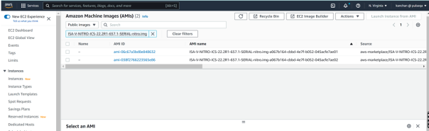
To deploy 2-NIC or 3-NIC in an existing VPC and new VPC respectively using the links above.
ICS gateway AMIs are available in all AWS regions (except China).
Deploying AWS Cloud ICS using Terraform Template
This section describes how to install terraform template, and deploy ICS on aws with 2 NICs and 3 NICs.
Installing Terraform Template
1.Go to the Terraform website and install Terraform on a Linux VM of your choice at usr/local/bin.
2.Install AWS CLI.
3.Configure AWS Access key and AWS Secret key under .bashrc directory.
Example: AWS_ACCESS_KEY="XXXXXXXX"; export AWS_ACCESS_KEY
AWS_SECRET_KEY="YYYYYYYY"; export AWS_SECRET_KEY
4.Deploy the ICS using the Terraform Template. To download the Cloud Templates, see product-downloads.
To configure the required password:
1.Locate pulse-config within the .tf file.
2.Assign the desired value to the admin-password field.
Configuring Base Setup
1.Customize and set the variables in variables.tf file based on the requirement.
Example: Region, AMI-id, VPC name, subnet IP address details, instance name etc.
2.Create a directory base_setup.
3.Copy the files variables.tf and base_setup.tf into the base_setup directory.
4.Change the key based on your requirement.
5.Change the files permission with +x .
linux# chmod +x *.*
6.Run the following commands creating base setup.:
linux# terraform init
linux# terraform apply
7.When prompted for admin input for deployment, type "yes".
The Base setup will create VPC, Subnets, Security Groups, Internet Gateway and Route Table.
Deploying ICS with 2 NICs
1.Customize and set the variables in variables.tf file based on the requirement.
2.Change directory to ics_2_nics.
3.Copy the files variables.tf and ics_2_nics.tf into the ics-2nic directory.
4.Run the following commands:
linux# terraform init
linux# terraform apply
This terraform will deploy 2 NIC ICS.
Deploying ICS with 3 NICs
1.Customize and set the variables in variables.tf file based on the requirement.
2.Change directory to ics_3_nics.
3.Copy the files variables.tf and ics_3_nics.tf into the ics-3nic directory.
4.Run the following commands:
linux# terraform init
linux# terraform apply
This terraform will deploy 3 NIC ICS.
Ivanti Connect Secure Provisioning Parameters
Provisioning parameters are those parameters which are required during the deployment of a virtual appliance. Ivanti Connect Secure accepts the following parameters as provisioning parameters in the XML format.
<pulse-config>
<primary-dns><value></primary-dns>
<secondary-dns><value></secondary-dns>
<wins-server><value></wins-server>
<dns-domain><value></dns-domain>
<admin-username><value></admin-username>
<admin-password><value></admin-password>
<cert-common-name><value></cert-common-name>
<cert-random-text><value></cert-random-text>
<cert-organisation><value></cert-organisation>
<config-download-url><value></config-download-url>
<config-data><value></config-data>
<auth-code-license><value></auth-code-license>
<enable-license-server><value></enable-license-server>
<accept-license-agreement><value></accept-license-agreement >
<enable-rest><value></enable-rest>
<registration-code> 1grkL2Xbr </registration-code>
<registration-fqdn>auto.toad.pzt.dev.perfsec.com</registration-fqdn>
<enable-proxy>n</enable-proxy>
<proxy-host></proxy-host>
<proxy-port></proxy-port>
<proxy-username></proxy-username>
<proxy-password></proxy-password>
<register-network-interface>external</register-network-interface>
</pulse-config>
The below table depicts the details of the xml file.
|
# |
Parameter Name |
Type |
Description |
|
1 |
wins-server |
IP address |
Wins server for Ivanti Connect Secure |
|
2 |
dns-domain |
string |
DNS domain of Ivanti Connect Secure |
|
3 |
cert-common-name |
string |
Common name for the self-signed certificate generation. This certificate is used as the device certificate of Ivanti Connect Secure Random text for the self-certificate generation Organization name for the self-signed certificate generation |
|
4 |
cert-random-text |
string |
|
|
5 |
cert-organization |
string |
|
|
6 |
config-download-url |
String URL |
Http based URL where XML based Ivanti Connect Secure configuration can be found. During provisioning, Ivanti Connect Secure fetches this file and comes up with preloaded configuration. XML based configuration can be present in another VM in AWS cloud or at corporate network which is accessible for Ivanti Connect Secure through site to site VPN between AWS and corporate data center |
|
7 |
config-data |
string |
base64 encoded XML based Ivanti Connect Secure configuration |
|
8 |
auth-code-license |
string |
Authentication code that needs to be obtained from Ivanti |
|
9 |
enable-license-server |
string |
If set to ‘y’, ICS will be deployed as a License server. If set to ‘n’, ICS will be deployed as a normal server. |
|
10 |
accept-license-agreement |
string |
This value is passed to the instance for configuration at the boot time. By default, this value is set to “n”. This value must be set to “y”. |
|
11 |
enable-rest |
string |
If set to ‘y’, REST API access for the administrator user is enabled. |
- In the above list of parameters, primary dns, dns domain, admin username, admin password, cert-random name, cert-random text, cert-organization and accept-license-agreement are mandatory parameters. The other parameters are optional parameters.
- The XML parsing fails if the following characters are used in the strings:
- "
- ’
- <
- >
- &
- Ivanti Connect Secure supports zero touch provisioning. This feature can detect and assign DHCP networking settings automatically at the Ivanti Connect Secure boot up. The Ivanti Connect Secure parameters should be set to null in order to fetch the networking configuration automatically from the DHCP server.
The below table describes the new parameters that are added in the XML file and these are applicable only for nSA-managed 9.x and ICS 21.x versions.
|
Parameter |
Type |
Description |
|---|---|---|
|
registrationCode |
string |
The registration code, which is generated during the ICS gateway registration on nSA. Example: KyZR6YDL8 |
|
registrationFQDN |
string |
The registration FQDN name, which is generated during the ICS gateway registration on nSA. Example: sample.domain.com |
|
enableproxy |
string |
Default is set to n. |
|
proxyHost |
string |
The proxy server name. |
|
proxyPort |
integer |
The port number of the proxy server. Example: 8080 |
|
proxyUsername |
string |
The username of the proxy server. Example,:usr |
|
proxyPassword |
string |
The password of the proxy server. Example: pxx124 |
|
registerNetworkInterface |
string |
The interface through which the gateway registers with nSA. Example: external |
Provisioning Ivanti Connect Secure with Predefined Configuration
The Ivanti Connect Secure Virtual Appliance can be provisioned on AWS with a predefined Ivanti Connect Secure configuration. The provisioning can be done in the following two ways:
•Ivanti Connect Secure administrator needs to provide the location of the XML-based configuration as a provisioning parameter. Refer Ivanti Connect Secure Provisioning Parameters for details about the Ivanti Connect Secure specific provisioning parameters.
•Ivanti Connect Secureconfiguration can be kept on AWS or on a machine located in the corporate network. If it is in the corporate network, the Ivanti Connect Secure administrator needs to ensure that site-to-site VPN between AWS to corporate network is already established so that Ivanti Connect Secure can access the machine located in the corporate network.
•Ivanti Connect Secure administrator provides the configuration data encoded in the base64 encoded xml in the CloudFormation template.
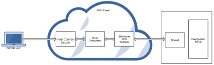
Configuring Licenses on the Ivanti Connect Secure Appliance
Evaluation licenses are provided, to add more licenses, the Ivanti Connect Secure administrator needs to leverage the Ivanti License server.
Ivanti License Server in Corporate Network
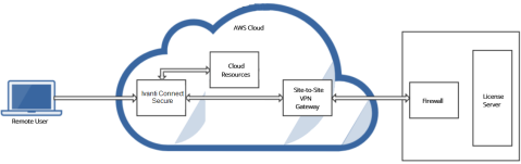
Ivanti License Server in Cloud Network
Ivanti Connect Secure virtual machines (VM) are enabled to provision licenses through the Ivanti Cloud Licensing Service. For this, administrator needs to obtain an Authentication code from Ivanti Support and apply it in Download Licenses page of ICS admin console. The ICS also periodically sends heartbeat messages to CLS for auditing purposes.

The Authentication code can also be specified in the CloudFormation template. When ICS comes up, it automatically fetches the Authentication code.
•Adding Authentication Code in ICS Admin Console
•Including Authentication Code in CloudFormation Template
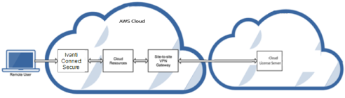
Adding Authentication Code in ICS Admin Console
To add Authentication code:
5.Go to System > Configuration > Licensing > Download Licenses.
6.Under On demand license downloads, enter the Authentication code in the text box.
7.Click on Download and Install. For more info see Gateway Licensing.
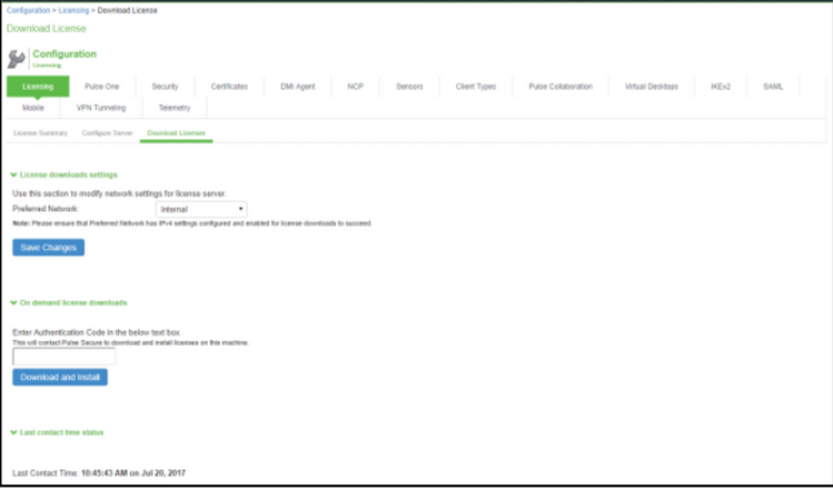
Including Authentication Code in CloudFormation Template
To include Authentication code in the CloudFormation template:
•In the CloudFormation template, go to the ICSConfig section.
•For the element <auth-code-license>, enter the Authentication code as the content.
•Save the template.
For details about the license configuration, refer to License Configuration Guide.
System Operations
The AWS portal provides Start, Restart Stop and Terminate operations to control the Virtual Appliance connection.
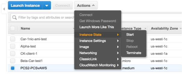
On the AWS portal, select AWS Services > Launch Instance. From the Actions menu, select Instance State.
•Click Start to start a VM
•Click Stop to stop the VM
•Click Restart to restart the VM
•Click Terminate to terminate the VM
Network Configuration
IP Address Assignment for Internal, External and Management Interfaces
Each interface in AWS can have private and public IP addresses. Sample CloudFormation Templates provided by Ivanti Connect Secure creates the Ivanti Connect Secure Virtual Appliance with public and private IP addresses for external and management interfaces and only private IP address for internal interface. More details about IP address types on AWS can be seen at: https://docs.aws.amazon.com/AmazonVPC/latest/UserGuide/vpc-ip-addressing.html
IP Addressing Modes
When Ivanti Connect Secure gets deployed by using the sample templates provided by Ivanti, Ivanti Connect Secure comes up with multiple interfaces. If you take an example of a template “pulsesecure-ICS-3-nics.zip” provided by Ivanti, you notice the following things.
ICS external interface and ICS management interface have both Elastic and Private IP addresses.
Modifying Network Parameters After Deployment
Since Networking Infrastructure is provided by AWS, a ICS admin cannot change Networking configuration after deployment. Hence, both admin UI and ssh do not support changing network configuration.
Controlling the Selection of Internal, External and Management Interfaces
Sample CloudFormation template, provided by Ivanti, requests AWS fabric to create three Network Interfaces. While running this template, AWS fabric creates interfaces named eth0, eth1 and eth2 and attaches them to ICS Virtual Interface.
So, the question is, among eth0, eth1 and eth2 which network interface will become external, internal or management interface? Below table answers this question.
|
Interface Name |
ICS Interface |
|
eth0 |
internal interface |
|
eth1 |
external interface |
|
eth2 |
management interface |
Then, question is how you can control the order of network interfaces named eth0, eth1 and eth2 created through CloudFormation template?
The Ivanti Connect Secure Virtual Appliance is qualified with internal interface as primary and other two are secondary. In the following code snippet, three network interfaces get assigned to VM. These three NICs with ID “nic1”, “nic2” and “nic3” are internally mapped to ‘eth0’, ‘eth1’, and ‘eth2’ respectively.
"EC2Instance": {
"Type": "AWS::EC2::Instance",
"DependsOn": [
"EIPAssoc0",
"EIPAssoc1"
],
"Properties": {
"ImageId": {
"Fn::FindInMap": [
"ICSAMI",
{
"Ref": "AWS::Region"
},
"img"
]
},
"KeyName": {
"Ref": "KeyName"
},
"InstanceType": {
"Ref": "InstanceType"
},
"NetworkInterfaces": [
{
"NetworkInterfaceId": {
"Ref": "Eth0"
},
"DeviceIndex": "0"
},
{
"NetworkInterfaceId": {
"Ref": "Eth1"
},
"DeviceIndex": "1"
}
],
ICS converts eth0 to int0, eth1 to ext0 and eth2 to mgmt0. This means, the network interface with ID nic1 will be internal interface, nic2 will be external interface and nic3 will be management interface.
The below table depicts this scenario well:
|
Interface Name |
ICS Interface |
Network ID |
|
eth0 |
internal interface |
nic1 |
|
eth1 |
external interface |
nic2 |
|
eth2 |
management interface |
nic3 |
Accessing the Ivanti Connect Secure Virtual Appliance
Accessing the Ivanti Connect Secure Virtual Appliance as an Administrator
In the AWS portal, navigate to CloudFormation section. Select the stack where ICS is deployed and then click on the ‘Outputs’ tab. Note down the ICS management, internal and external address from the table as shown in figure.
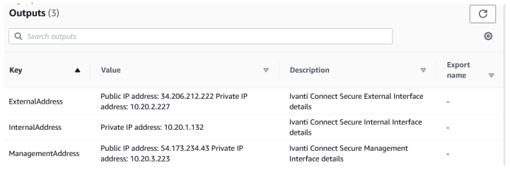
Use the credentials provided in the provisioning parameters to log in as the administrator in the ICS Admin interface with URL https://<PCS-IP>/admin. The default ICS Admin UI user configured in the CloudFormation config file is: user ‘admin’ and password ‘password1234’.
The administrator can configure Active Directory located in the corporate network for user authentication. The Ivanti Connect Secure Virtual Appliance administrator can check troubleshooting tools provided in the Ivanti Connect Secure admin UI (System > Maintenance > Troubleshooting), to verify whether Ivanti Connect Secure is able to reach other cloud resources as well as corporate resources. For this, AWS network administrator needs to ensure that all other resources have Ivanti Connect Secure Internal interface as its default gateway.
Accessing the Ivanti Connect Secure Virtual Appliance as an End User
After successfully deploying ICS on AWS, go to the Outputs section and copy the Ivanti External Interface details.
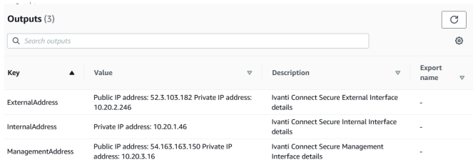
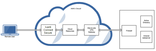
Seamless Migration of ICS configuration on AWS
Overview
This section describes the seamless migration of the ICS configuration on Amazon Web Services.
Process
The process for seamless migration of the ICS configuration on AWS marketplace is as follows:
1.Setting up and deploying a new VM, refer Custom Ivanti Connect Secure Deployment on AWS Portal.
2.ICS configuration migration, refer Provisioning Ivanti Connect Secure with Predefined Configuration.
3.License migration, refer Configuring Licenses on the Ivanti Connect Secure Appliance.
4.Network IP address migration.
Before You Begin
1.Deploy a ICS in AWS environment with new software version, possibly with existing Virtual Private Cloud instance. Note down the private and public IP addresses.
2.Check the reachability of the ICS using public IP address for newly deployed ICS.
3.Perform a cleanup of the appliance before exporting the user.cfg to reduce the size of the user configuration file.
•Disable any debug logging
•Delete logs
•Delete any old snapshots
•Clear event logs
•Delete old ESAP
•Delete old Ivanti Clients
•Clean up external user records
Network IP address Migration
To change IP address of the ICS instance on AWS for internal and external ports:
1.In the AWS environment, navigate to Elastic IP dashboard of port network settings. Select the public IP address entry and select Disassociate Elastic IP address under Actions.
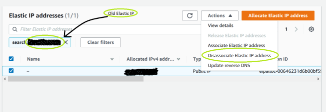
2.Select the private IP address entry and select Disassociate address under Actions.
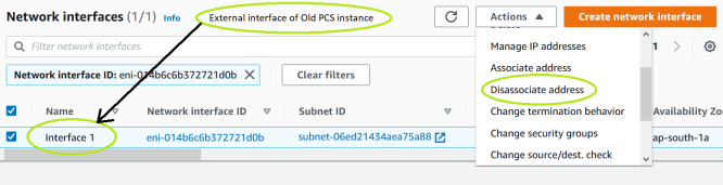
3.For external port interface, select the entry and select Delete under Actions.
Internal port is associated as primary interface of the ICS deployed earlier. For internal port IP address migration, AWS console does not allow to delete the specific interface. Admin needs to delete the instance and then associate the internal port.
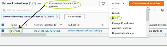
4.Navigate to the port interface of the newly deployed ICS, click Actions and select Manage IP addresses.
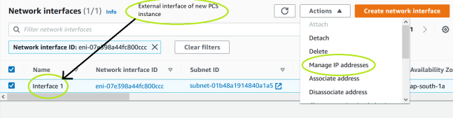
5.Enter the IP address of the ICS instance and select Assign new IP address.
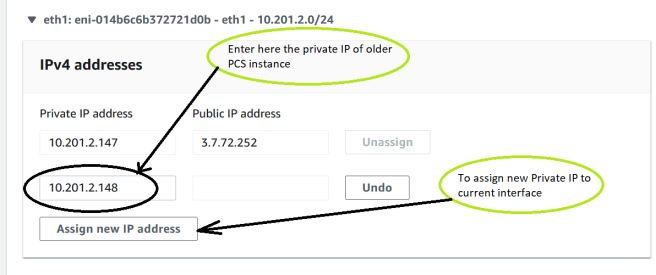
6.Select the public IP entry again and select Associate Elastic IP address under Actions.
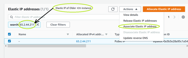
7.Select the private IP address of the newly deployed ICS. Select Network interface, enter the interface ID in Network Interface field.
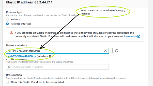
8.The list of configured IPs automatically populates under Private IP address field. Select the IP address as configured in ICS and click Associate.
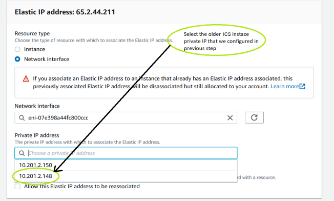
9.In the port network interface for the newly deployed ICS, select the Elastic IP address and navigate to Actions View Details. View and verify the elastic IP address associated to the secondary IP address.
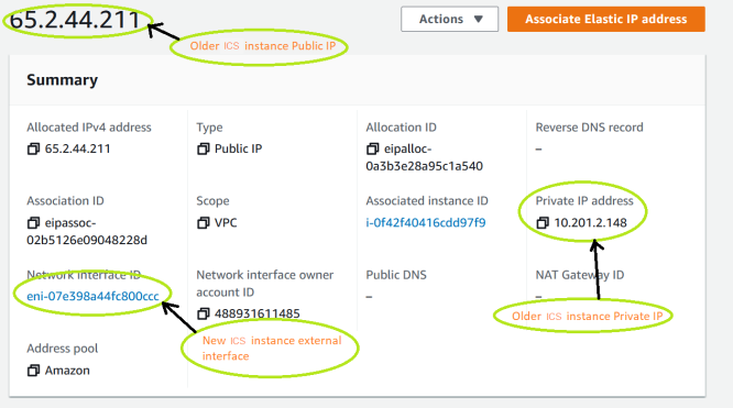
10. Login to newly deployed ICS and modify the external port IP address to older ICS external port address.
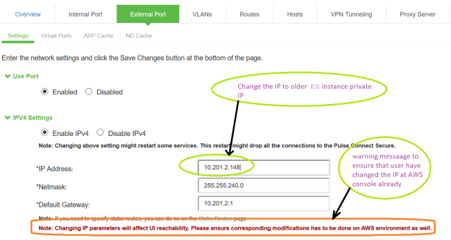
11.Login as end user using the elastic IP address (assigned for secondary private IP address) and verify that end user login is successful.
Troubleshooting
Ivanti Connect Secure emits booting logs at a specified storage. You can check the storage details of the boot diagnostic logs as shown below:
1.Select AWS Services > Instances > Launch Instance.
2.From the list displayed, select Instance Settings > Get System Log.
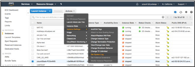
The system logs window is displayed.
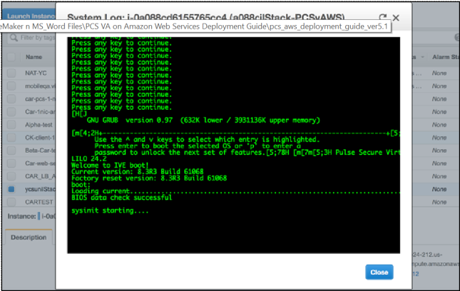
Deploying Ivanti Connect Secure Appliance on GCP
Prerequisites and System Requirements
To deploy the Ivanti Connect Secure Virtual Appliance on GCP, you need the following:
•Google Cloud Platform account
•Access to the GCP portal (https://cloud.google.com/ )*
•Ivanti Connect Secure Virtual Appliance Image
•Ivanti Connect Secure licenses **
•Ensure that you have enough IP address in your region
•Ensure that you have already created VPC network for each interface, as this is required while you deploy VM instances.
Before you Begin
Before you start, make sure you have the following information and files:
•Signature database file : https://pulsezta.blob.core.windows.net/gateway/nsa/db.der
•To create a GCP image : https://pulsezta.blob.core.windows.net/gateway/nsa/templates/GCP/<package name>/ivanti-ics-image.zip
Downloading the GCP Virtual Machine Image
Download ICS image which is in zip format from Ivanti support site. Unzip the file to a location that is accessible from Google Cloud Platform.
Uploading the GCP Virtual Machine Image onto the Google Cloud Platform
To upload a GCP Gateway virtual machine image into Google Cloud Platform:
1.Access the Google Cloud Platform Management Portal, either from a client or a web browser, and log in using your Google Cloud Platform credentials.
2. In the Google Cloud Platform console, select your required project from the pull-down list on the title bar. For example:

3.Click the Navigation menu, and then select Cloud Storage > Browser.
A list of GCP storage buckets appears.
4.Select the bucket into which you wish to place the GCP image.
A page listing the current contents of the bucket appears.
5.(Optional) Navigate to the required folder within the bucket.
6.Click Upload Files. For example:
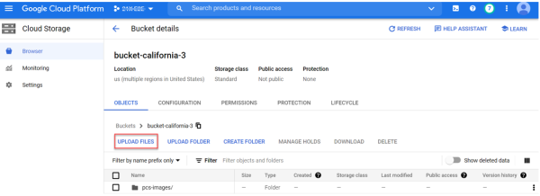
An upload dialog appears.
7.Select the ICS Gateway GCP virtual machine image .tar file from your local workstation (see Before you begin), and click Open.
If you want to use the provided YAML templates to automate the creation of the GCP image (see Creating a VM Instance of the Uploaded GCP Image Using a Script/Template), select these in addition to the image archive.
The image archive and any selected template files are added to the bucket.
8.Wait until the upload completes. This may take several minutes.
9.Start a command line session from the title bar. For example:

A command line session starts.
10.Navigate to the project folder.
11.Copy the db.der file extracted from the ICS image .zip file, to the current project directory.
12.Create an image using the following command using GCP CLI:
gcloud compute images create <image_name> --source-uri=gs://<bucket_name>/<optional_path>/<image_name>.tar.gz --signature-database-file=db.der --guest-os-features MULTI_IP_SUBNET,UEFI_COMPATIBLE,GVNIC
For example:
gcloud compute images create pcs109 --source-uri=gs://bucket-california/pcs_images/ICS-25.13R1-25.13R1-145.1.tar.gz --signature-database-file=db.der --guest-os-features MULTI_IP_SUBNET,UEFI_COMPATIBLE,GVNIC
13.You can also create an image using a script/template (see Creating a GCP Image Using a Script/Template)
14.You can now create a VM instance of the uploaded GCP image. To do this, either:
•Perform the task manually, see Creating a VM Instance of the Uploaded GCP Image Manually.
•Perform the task with a script/template, see Creating a VM Instance of the Uploaded GCP Image Using a Script/Template.
Creating a GCP Image Using a Script/Template
1.Download the required template archive file to your local workstation. https://pulsezta.blob.core.windows.net/gateway/nsa/templates/GCP/21-12-145/ivanti-ics-image.zip
2.Unpack the downloaded archive file to a location that is accessible from Google Cloud Platform. Each archive contains three files present in one respective directory, i.e.:
•ivanti-ics-image.jinja
•ivanti-ics-image.scheme
•ivanti-ics-image.yaml
3.Edit the YAML file properties section to reflect your project requirements.
An example of an existing VPC YAML file is provided here:
imports:
- path: ivanti-ics-image.jinja
resources:
- name: ivanti-custom-secure-image
type: ivanti-ics-image.jinja
properties:
image_name: icsgcp123
bucket_name: bucket-california
image_file: ICS-25.13R1-25.13R1-145.1.tar.gz
# Paste your Base64 encoded file lines directly here:
db_content: <BASE64_STRING_FROM_DB.DER>
4.Save the YAML file.
5.On the Google Cloud Platform, start a command line session from the title bar. For example:
A command line session starts.
6.Within the project folder, change to deploymentmanager folder.
7.Create a new folder and change to the new folder and copy the three script files to this folder.
8.Select the required project:
gcloud config set project <project-name>
9.Create the GCP image using the following command:
gcloud deployment-manager deployments create <image-name> --config <yaml_file>
For example:
gcloud deployment-manager deployments create icsgcp123 --config ivanti-ics-image.yaml
Creating a VM Instance of the Uploaded GCP Image Manually
This section describes how to manually create a virtual machine instance of the ICS Gateway image inside Google Cloud Platform. You can also perform this process automatically using a script/template, see Creating a VM Instance of the Uploaded GCP Image Using a Script/Template.
1.Click the Navigation menu, and then select Compute Engine > Images.
The Images page appears. For example:
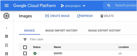
2.Locate the new image in the list of images.
3.At the end of the image entry, click the action menu and select Create Instance.
The Create Instance page appears. For example:
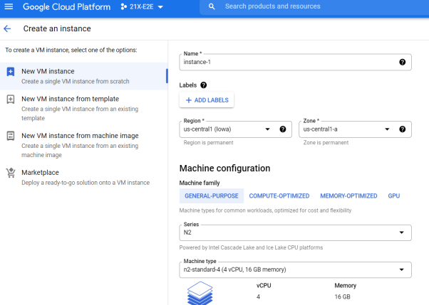
4.On the Create Instance page:
For more information, see table below.
|
General-Purpose |
CPUs / Memory |
ISA Model |
Disk Space |
|---|---|---|---|
|
N4 (5th Gen Intel Xeon Scalable processor) |
n4-standard-4 (4 vCPU, 16 GB) |
ISA4500V |
80 GB |
| n4-standard-8 (8 vCPU, 32 GB) |
ISA6500V |
80 GB | |
| n4-standard-16 (16 vCPU, 64 GB) |
ISA8500V |
80 GB |
•Enter a Name for the new instance.
•Select a Region and Zone.
•Under Machine configuration:
•For Series, select n4-standard-4.
•For Machine Type, select a minimum of n4-standard-4.
•For Boot Disk, confirm that the correct image is already selected.
•For Firewall, select the required HTTP/HTTPS options.
•Under Security → Shielded VM
•Select Turn on Secure Boot
•Select Turn on vTPM
•Deselect Turn on Integrity Monitoring
•Expand the Management, security, disks, networking, sole tenancy options.
•Select the Management tab.
•Under Metadata:
•For Key, enter pulse-config.
•For Value, paste the text of the metadata file..
•Select the Networking tab.
•Under Network interfaces, click the Edit icon to change the default network interface selection.
The Network interface options appear.
•Under Network interface, specify a private (internal) network interface:
•For Network, select the required private VPC.
•For Subnetwork, select the required subnetwork.
•Click Done to confirm the settings for the private network interface.
•Under Network interfaces, click Add network interface.
The Network interface options appear.
•Under Network interface, specify a public (external) network interface:
•For Network, select the required public VPC.
•For Subnetwork, select the required subnetwork.
•Click Done to confirm the settings for the public network interface.
•(Optional) Click Add network interface and specify a management network interface.
•Click Create to confirm the settings and instantiate a VM instance of the image.
The VM Instances page appears. This page shows the new VM instance of the image. For example:

5.On the VM Instances page, wait until the creation of the VM instance completes. This may take several minutes.
6.After the VM instance is created, click on it in the list of VM instances.
The VM instance details page appears for the instance.
7.Confirm the details for the VM instance, including the number of network interfaces.
8.Make a note of the public IP address of the EXT interface (typically, this is nic1. This is required inside nSA.
9.Under Network interfaces, confirm that the firewall settings from your VPCs are present for your specified network interfaces:
•Click nic0. A summary page for this network interface appears.
Under Firewall and route details, click the Firewall Rules tab and confirm that the following firewall rules are defined.
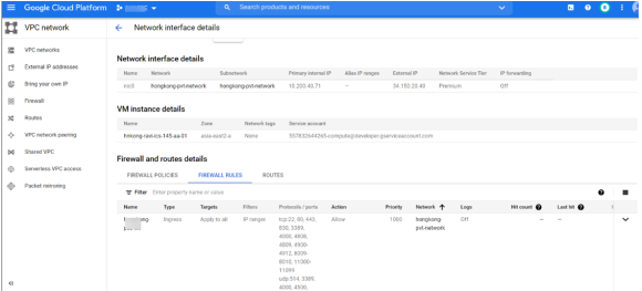
•Click nic1. A summary page for this network interface appears.
Under Firewall and route details, click the Firewall Rules tab and confirm that the following firewall rules are defined.
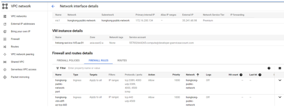
•(Optional) Click nic2. A summary page for this optional network interface appears.
Under Firewall and route details, click the Firewall Rules tab and confirm that the following firewall rules are defined.
10.The VM instance details* page, click Connect to serial console
A console monitor view (in a separate browser tab) shows the ongoing boot-up process for the instance.
11.Wait until the instance boot up is complete, and shows a screen similar to the following:
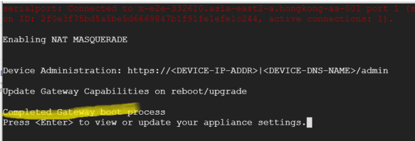
You can then complete this process by updating the Gateway details on the nSA Controller, see Completing the Configuration of the nSA Controller.
Creating a VM Instance of the Uploaded GCP Image Using a Script/Template
This section describes how to automatically create a virtual machine instance of the ICS Gateway image inside Google Cloud Platform using a script/template. You can also perform this process manually, see Creating a VM Instance of the Uploaded GCP Image Manually.
Ivanti provides YAML-based templates to create an instance of the ICS Gateway image in the following configurations:
•Two network interfaces in an existing VPC.
•Three network interfaces in an existing VPC.
Download:
https://pulsezta.blob.core.windows.net/gateway/nsa/templates/GCP/21-12-145/ivanti-ics-2-nics-existing-vpc.zip
https://pulsezta.blob.core.windows.net/gateway/nsa/templates/GCP/21-12-145/ivanti-ics-3-nics-existing-vpc.zip
•Two network interfaces in a new VPC.
•Three network interfaces in a new VPC.
Download:
https://pulsezta.blob.core.windows.net/gateway/nsa/templates/GCP/21-12-145/ivanti-ics-2-nics-new-vpc.zip
https://pulsezta.blob.core.windows.net/gateway/nsa/templates/GCP/21-12-145/ivanti-ics-3-nics-new-vpc.zip
To use a template:
1.Download the required template archive file to your local workstation.
2.Unpack the downloaded archive file to a location that is accessible from Google Cloud Platform. Each archive contains three files. These files should be present in one respective directory. For example, for the three-interface (existing VPC) version of the archive:
ivanti-ics-2-nics-existing-vpc.jinja
ivanti-ics-2-nics-existing-vpc.scheme
ivanti-ics-2-nics-existing-vpc.yaml
3.Edit the YAML file properties section to reflect your project and instance requirements, including the user_data property.
An example of an existing VPC YAML file is provided here:
|
imports: - path: ivanti-ics-3-nics-existing-vpc.jinja resources: - name: my-vm properties: project: ics-project email: [email protected] machinetype: n2-standard-4 region: asia-south1 zone: asia-south1-b image: icsgcp123 int_network: vpc-network-private-abcdef ext_network: vpc-network-public-abcdef mgmt_network: vpc-network-mgmt-abcdef int_subnetwork: vpc-asia-south1-b-ics-int-port ext_subnetwork: vpc-asia-south1-b-ics-ext-port mgmt_subnetwork: vpc-asia-south1-b-ics-mgmt-port user_data: <pulse-config><primary-dns>8.8.8.8<\primary-dns> ... type: ivanti-ics-3-nics-existing-vpc.jinja enableSecureBoot: true enableVtpm: true enableIntegrityMonitoring: false |
The following table lists all possible template properties and their meaning:
|
Property |
Description |
|---|---|
|
project |
Name of the Project |
|
|
Registered service account email address |
|
region |
The name of the region in which you want to deploy your VM instance |
|
zone |
The name of the zone in which you want to deploy your VM instance |
|
image |
Virtual machine image name |
|
machine_type |
N2-standard machine type |
|
int_network |
VPC network name for internal network |
|
ext_network |
VPC network name for external network |
|
mgmt_network |
VPC network name for management network |
|
int_subnetwork |
Subnet name for internal VPC |
|
ext_subnetwork |
Subnet name for external VPC |
|
mgmt_subnetwork |
Subnet name for management VPC |
|
user_data |
The Gateway config file downloaded. In User data, <networkConnection>v4</networkConnection> parameter can be configured as follows: •v4 : IPv4 addresses are allowed to configured (Default). |
4. Save the YAML file.
5.On the Google Cloud Platform, start a command line session from the title bar. For example:

A command line session starts.
6.Within the project folder, change to deploymentmanager folder.
7.Create a new folder and change to the new folder and copy the three script files to this folder.
8. Select the required project:
gcloud config set project <project-name>
9.Deploy the VM using the following command:
gcloud deployment-manager deployments create <vm-name> --config <yaml_file>
For example:
gcloud deployment-manager deployments create vm-gcp-123 --config ivanti-ics-3-nics-existing-vpc.yaml
10.Wait until the command completes.
11.On the VM Instances page, click on the new VM in the list of VM instances.
The VM instance details page appears for the instance.
Increasing the Disk Space in GCP
From 22.6R2 release , on fresh installation 80 GB disk space is available by default. You can modify or increase the disk size only once on fresh installation or upgrade of the ICS images, but not on rollback or factory reset images.
If the user is upgrading to 22.6R2 or later, then the disk size change from 40 GB to 80 GB have to be done prior to upgrade on Google cloud platform.
Disk Size Allocation is supported from 22.6R2 and later releases.
1.On the Google Cloud console, go to the Disks page. Go to Disks.
2.In the list of persistent disks in your project, click the name of the disk that you want to resize.
3.On the disk details page, click Edit. You might need to click the ⋮> More actions menu and then click Edit.
4.In the Size field, enter the new size for your disk.
5.Click Save to apply your changes to the disk.
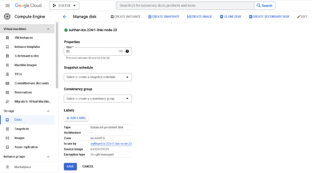
Deploying ICS using Terraform Template
This section describes how to install terraform template and deploy ICS on GCP with 2 NICs and 3 NICs.
1.Copy variables, base_setup_tf and ics_deploy scripts to a linux m/c installed with terraform. Go to the Terraform website to install Terraform on a Linux VM of your choice at usr/local/bin.
2.Create base_setup directory and copy base_setup.tf and variables.tf to it. Customize and set the variables in variables.tf file based on the requirement.
Example: Region, AMI-id, VPC name, subnet IP address details, instance name etc.
3.cd to base_setup directory and run terraform apply.
linux# terraform apply
4.Create ics_deploy directory and copy ics_deploy and variables.tf to it
5.Run following command:
terraform apply -input=false -auto-approve -var "instance_name=gcp-test-instance-1" -var "image_name=icsgcp386"
Before running the script, user has to create an image in the GCP cloud in the name of icsgcp386 (as shown above)
Downloading Terraform Template File
To download Terraform Template zip file:
1.Log in to https://portal.ivanti.com/customer/product-downloads
2.Navigate to Security> Ivanti Connect Secure (ICS, Pulse Connect Secure) > Downloads > Pulse Secure > Pulse Connect Secure > Cloud Templates.
3.Under Current and Supported Releases, select the Template file and Download. For example, ps-ics-terraform_templates-9.1Rx_22.Rx-2.0.zip.
Ivanti Connect Secure Provisioning Parameters
Provisioning parameters are those parameters which are required during the deployment of a virtual appliance. Ivanti Connect Secure accepts the following parameters as provisioning parameters in the XML format.
<pulse-config>
<primary-dns><value></primary-dns>
<secondary-dns><value></secondary-dns>
<wins-server><value></wins-server>
<dns-domain><value></dns-domain>
<admin-username><value></admin-username>
<admin-password><value></admin-password>
<cert-common-name><value></cert-common-name>
<cert-random-text><value></cert-random-text>
<cert-organisation><value></cert-organisation>
<config-download-url><value></config-download-url>
<config-data><value></config-data>
<auth-code-license><value></auth-code-license>
<enable-license-server><value></enable-license-server>
<accept-license-agreement><value></accept-license-agreement >
<enable-rest><value></enable-rest>
<registration-code> 1grkL2Xbr </registration-code>
<registration-fqdn>auto.toad.pzt.dev.perfsec.com</registration-fqdn>
<enable-proxy>n</enable-proxy>
<proxy-host></proxy-host>
<proxy-port></proxy-port>
<proxy-username></proxy-username>
<proxy-password></proxy-password>
<register-network-interface>external</register-network-interface>
</pulse-config>
The below table depicts the details of the xml file.
|
# |
Parameter Name |
Type |
Description |
|
1 |
wins-server |
IP address |
Wins server for Ivanti Connect Secure |
|
2 |
dns-domain |
string |
DNS domain of Ivanti Connect Secure |
|
3 |
cert-common-name |
string |
Common name for the self-signed certificate generation. This certificate is used as the device certificate of Ivanti Connect Secure Random text for the self-certificate generation Organization name for the self-signed certificate generation |
|
4 |
cert-random-text |
string |
|
|
5 |
cert-organization |
string |
|
|
6 |
config-download-url |
String URL |
Http based URL where XML based Ivanti Connect Secure configuration can be found. During provisioning, Ivanti Connect Secure fetches this file and comes up with preloaded configuration. XML based configuration can be present in another VM in AWS cloud or at corporate network which is accessible for Ivanti Connect Secure through site to site VPN between AWS and corporate data center |
|
7 |
config-data |
string |
base64 encoded XML based Ivanti Connect Secure configuration |
|
8 |
auth-code-license |
string |
Authentication code that needs to be obtained from Ivanti |
|
9 |
enable-license-server |
string |
If set to ‘y’, ICS will be deployed as a License server. If set to ‘n’, ICS will be deployed as a normal server. |
|
10 |
accept-license-agreement |
string |
This value is passed to the instance for configuration at the boot time. By default, this value is set to “n”. This value must be set to “y”. |
|
11 |
enable-rest |
string |
If set to ‘y’, REST API access for the administrator user is enabled. |
- In the above list of parameters, primary dns, dns domain, admin username, admin password, cert-random name, cert-random text, cert-organization and accept-license-agreement are mandatory parameters. The other parameters are optional parameters.
- The XML parsing fails if the following characters are used in the strings:
- "
- ’
- <
- >
- &
- Ivanti Connect Secure supports zero touch provisioning. This feature can detect and assign DHCP networking settings automatically at the Ivanti Connect Secure boot up. The Ivanti Connect Secure parameters should be set to null in order to fetch the networking configuration automatically from the DHCP server.
The below table describes the new parameters that are added in the XML file and these are applicable only for nSA-managed 9.x and ICS 21.x versions.
|
Parameter |
Type |
Description |
|---|---|---|
|
registrationCode |
string |
The registration code, which is generated during the ICS gateway registration on nSA. Example: KyZR6YDL8 |
|
registrationFQDN |
string |
The registration FQDN name, which is generated during the ICS gateway registration on nSA. Example: sample.domain.com |
|
enableproxy |
string |
Default is set to n. |
|
proxyHost |
string |
The proxy server name. |
|
proxyPort |
integer |
The port number of the proxy server. Example: 8080 |
|
proxyUsername |
string |
The username of the proxy server. Example,:usr |
|
proxyPassword |
string |
The password of the proxy server. Example: pxx124 |
|
registerNetworkInterface |
string |
The interface through which the gateway registers with nSA. Example: external |
Adding ICS Gateway to nSA
To add ICS Gateway, perform the following steps:
1.From the Ivanti Connect Secure menu, click the Gateways icon, then select Gateways > Gateways List.
The All Gateways page is displayed.
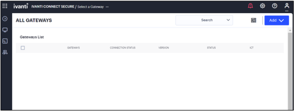
2.In the All Gateways page, click the Add drop-down list.

3.From the Gateway types list, select ICS Gateway.
The Register ICS Gateway page is displayed.
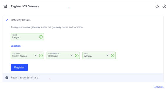
4.Enter a unique name for ICS gateway.
5.Enter your Location details such as Country, State/Region, City, and then click Register.
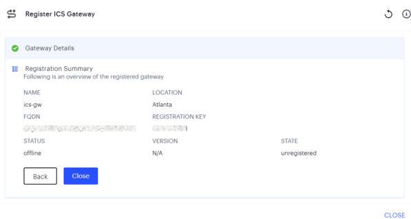
The Registration Summary page contains the FQDN URL and Registration Key, which you need to enter in the ICS Gateway to complete the registration. See Completing Registration of a ICS Appliance.
6.Click Close.
The newly added ICS Gateway gets listed as “Unregistered” under ICS Gateways list.
Completing Registration with ICS
We recommend you use NTP server to ensure the clocks are synchronized and features on Ivanti Neurons for Secure Access work properly.
To complete registration with ICS:
1.Log in to the ICS as an Admin.
2.Select the System > Configuration > Ivanti Neurons for Secure Access > Settings tab.
3.Enter the Registration FQDN and Registration Code.
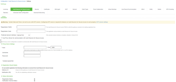
4.Click Save Changes.
The Status Information displays the Registration Status in green.
Checking a Current Gateway Version
To check the current version for a Gateway, and to apply an update:
1.Log into the nSA Controller as a Tenant Admin.
2.From the Ivanti Connect Secure menu, click the Gateways icon, then select Gateways > Gateway List.
The All Gateways page appears, showing the full list of Gateway Groups and standalone Gateways currently configured on the Controller.
3.Select the required Gateway from the list.
The Gateways Overview page appears. The summary at the top of the page displays details pertaining to this Gateway, including the current version:
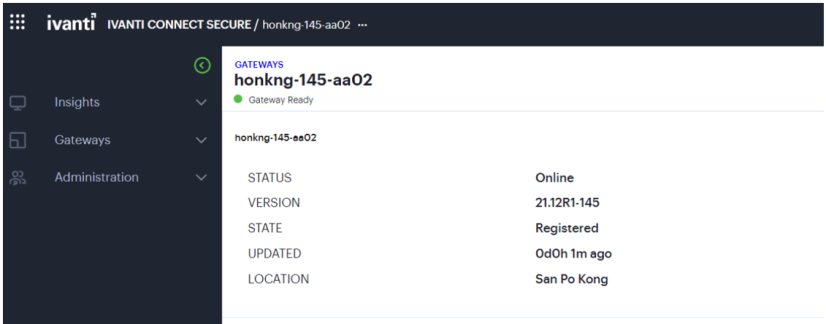
4.Click the context menu icon at the top-right to access the Edit options applicable to the selected Gateway:
FAQ
Q: I am unable to connect to my backend resources through L3 VPN.
Solution: SNAT these packets to the Internal interface IP which belongs to a subnet within the VPC.
To NAT endpoint tunnel IP to Internal interface IP, do the following:
1.Log in to Ivanti Connect Secure admin console.
2.Navigate to System > Network > VPN Tunneling.
3.Enable Source NATTING. By default, Source NATTING is disabled.

Q: User not able to access ICS after installation.
Solution: Ensure that the port 443 is opened for ICS