Deploying on Google Cloud Platform
•Prerequisites and System Requirements
•Downloading the GCP Virtual Machine Image
•Uploading the GCP Virtual Machine Image onto the Google Cloud Platform
•Creating a GCP Image Using a Script/Template
•Creating a VM Instance of the Uploaded GCP Image Manually
•Creating a VM Instance of the Uploaded GCP Image Using a Script/Template
•Increasing the Disk Space in GCP
•Deploying ICS using Terraform Template
•Ivanti Connect Secure Provisioning Parameters
Supported Platforms Systems
This section helps you in choosing the instance types that should be deployed with Ivanti Connect Secure.
•ISA4500-V
•ISA6500-V
•ISA8500-V
For more details, see ISA VA Supported Platforms.
Prerequisites and System Requirements
To deploy the Ivanti Connect Secure Virtual Appliance on GCP, you need the following:
•Google Cloud Platform account
•Access to the GCP portal (https://cloud.google.com/ )*
•Ivanti Connect Secure Virtual Appliance Image
•Ivanti Connect Secure licenses **
•Ensure that you have enough IP address in your region
•Ensure that you have already created VPC network for each interface, as this is required while you deploy VM instances.
Before you Begin
Before you start, make sure you have the following information and files:
•Signature database file : https://pulsezta.blob.core.windows.net/gateway/nsa/db.der
•To create a GCP image : https://pulsezta.blob.core.windows.net/gateway/nsa/templates/GCP/<package name>/ivanti-ics-image.zip
Downloading the GCP Virtual Machine Image
Download ICS image which is in zip format from Ivanti support site. Unzip the file to a location that is accessible from Google Cloud Platform.
Uploading the GCP Virtual Machine Image onto the Google Cloud Platform
To upload a GCP Gateway virtual machine image into Google Cloud Platform:
1.Access the Google Cloud Platform Management Portal, either from a client or a web browser, and log in using your Google Cloud Platform credentials.
2. In the Google Cloud Platform console, select your required project from the pull-down list on the title bar. For example:

3.Click the Navigation menu, and then select Cloud Storage > Browser.
A list of GCP storage buckets appears.
4.Select the bucket into which you wish to place the GCP image.
A page listing the current contents of the bucket appears.
5.(Optional) Navigate to the required folder within the bucket.
6.Click Upload Files. For example:
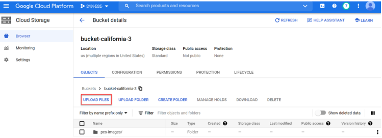
An upload dialog appears.
7.Select the ICS Gateway GCP virtual machine image .tar file from your local workstation (see Before you begin), and click Open.
If you want to use the provided YAML templates to automate the creation of the GCP image (see Creating a GCP Image Using a Script/Template), select these in addition to the image archive.
The image archive and any selected template files are added to the bucket.
8.Wait until the upload completes. This may take several minutes.
9.Start a command line session from the title bar. For example:

A command line session starts.
10.Navigate to the project folder.
11.Copy the db.der file extracted from the ICS image .zip file, to the current project directory.
12.Create an image using the following command using GCP CLI:
gcloud compute images create <image_name> --source-uri=gs://<bucket_name>/<optional_path>/<image_name>.tar.gz --signature-database-file=db.der --guest-os-features MULTI_IP_SUBNET,UEFI_COMPATIBLE,GVNIC
For example:
gcloud compute images create pcs109 --source-uri=gs://bucket-california/pcs_images/ICS-25.13R1-25.13R1-145.1.tar.gz --signature-database-file=db.der --guest-os-features MULTI_IP_SUBNET,UEFI_COMPATIBLE,GVNIC
13.You can also create an image using a script/template (see Creating a GCP Image Using a Script/Template)
14.You can now create a VM instance of the uploaded GCP image. To do this, either:
•Perform the task manually, see Creating a VM Instance of the Uploaded GCP Image Manually.
•Perform the task with a script/template, see Creating a VM Instance of the Uploaded GCP Image Using a Script/Template.
Creating a GCP Image Using a Script/Template
1.Download the required template archive file to your local workstation.
2.Unpack the downloaded archive file to a location that is accessible from Google Cloud Platform. Each archive contains three files present in one respective directory, i.e.:
•ivanti-ics-image.jinja
•ivanti-ics-image.scheme
•ivanti-ics-image.yaml
3.Edit the YAML file properties section to reflect your project requirements.
An example of an existing VPC YAML file is provided here:
imports:
- path: ivanti-ics-image.jinja
resources:
- name: ivanti-custom-secure-image
type: ivanti-ics-image.jinja
properties:
image_name: icsgcp123
bucket_name: bucket-california
image_file: ICS-25.13R1-25.13R1-145.1.tar.gz
# Paste your Base64 encoded file lines directly here:
db_content: <BASE64_STRING_FROM_DB.DER>
4.Save the YAML file.
5.On the Google Cloud Platform, start a command line session from the title bar. For example:
A command line session starts.
6.Within the project folder, change to deploymentmanager folder.
7.Create a new folder and change to the new folder and copy the three script files to this folder.
8.Select the required project:
gcloud config set project <project-name>
9.Create the GCP image using the following command:
gcloud deployment-manager deployments create <image-name> --config <yaml_file>
For example:
gcloud deployment-manager deployments create icsgcp123 --config ivanti-ics-image.yaml
Creating a VM Instance of the Uploaded GCP Image Manually
This section describes how to manually create a virtual machine instance of the ICS Gateway image inside Google Cloud Platform. You can also perform this process automatically using a script/template, see Creating a VM Instance of the Uploaded GCP Image Using a Script/Template.
1.Click the Navigation menu, and then select Compute Engine > Images.
The Images page appears. For example:
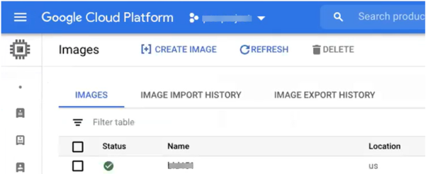
2.Locate the new image in the list of images.
3.At the end of the image entry, click the action menu and select Create Instance.
The Create Instance page appears. For example:
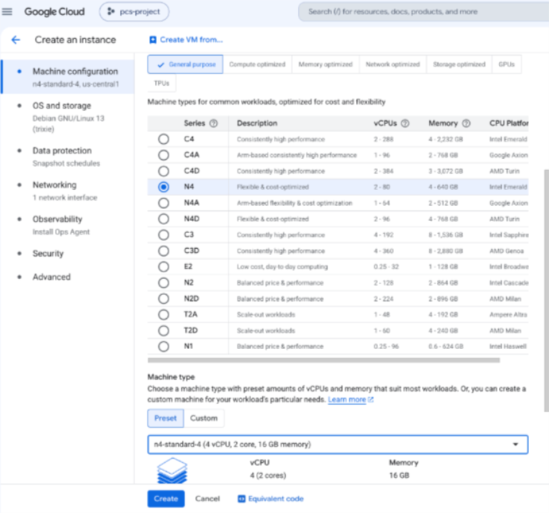
4.On the Create Instance page:
For more information, see table below.
|
General-Purpose |
CPUs / Memory |
ISA Model |
Disk Space |
|---|---|---|---|
|
N4 (5th Gen Intel Xeon Scalable processor) |
n4-standard-4 (4 vCPU, 16 GB) |
ISA4500V |
80 GB |
| n4-standard-8 (8 vCPU, 32 GB) |
ISA6500V |
80 GB | |
| n4-standard-16 (16 vCPU, 64 GB) |
ISA8500V |
80 GB |
•Enter a Name for the new instance.
•Select a Region and Zone.
•Under Machine configuration:
•For Series, select n4-standard-4.
•For Machine Type, select a minimum of n4-standard-4.
•For Boot Disk, confirm that the correct image is already selected.
•For Firewall, select the required HTTP/HTTPS options.
•Under Security → Shielded VM
•Select Turn on Secure Boot
•Select Turn on vTPM
•Deselect Turn on Integrity Monitoring
•Expand the Management, security, disks, networking, sole tenancy options.
•Select the Management tab.
•Under Metadata:
•For Key, enter pulse-config.
•For Value, paste the text of the metadata file..
•Select the Networking tab.
•Under Network interfaces, click the Edit icon to change the default network interface selection.
The Network interface options appear.
•Under Network interface, specify a private (internal) network interface:
•For Network, select the required private VPC.
•For Subnetwork, select the required subnetwork.
•Click Done to confirm the settings for the private network interface.
•Under Network interfaces, click Add network interface.
The Network interface options appear.
•Under Network interface, specify a public (external) network interface:
•For Network, select the required public VPC.
•For Subnetwork, select the required subnetwork.
•Click Done to confirm the settings for the public network interface.
•(Optional) Click Add network interface and specify a management network interface.
•Click Create to confirm the settings and instantiate a VM instance of the image.
The VM Instances page appears. This page shows the new VM instance of the image. For example:

5.On the VM Instances page, wait until the creation of the VM instance completes. This may take several minutes.
6.After the VM instance is created, click on it in the list of VM instances.
The VM instance details page appears for the instance.
7.Confirm the details for the VM instance, including the number of network interfaces.
8.Make a note of the public IP address of the EXT interface (typically, this is nic1. This is required inside nSA.
9.Under Network interfaces, confirm that the firewall settings from your VPCs are present for your specified network interfaces:
•Click nic0. A summary page for this network interface appears.
Under Firewall and route details, click the Firewall Rules tab and confirm that the following firewall rules are defined.
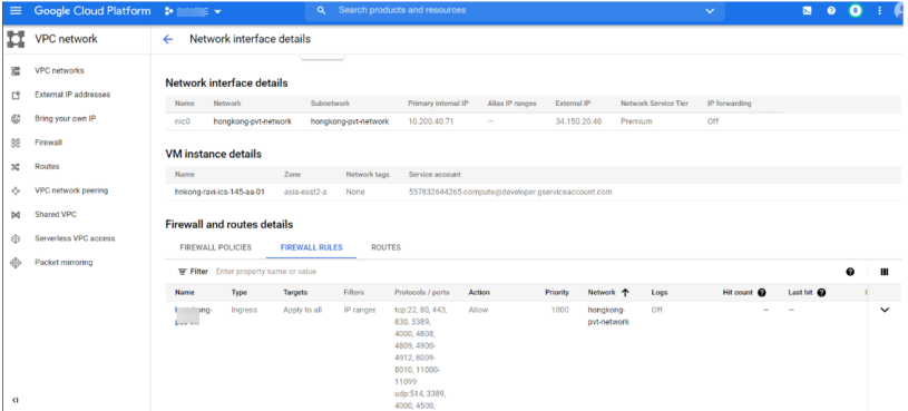
•Click nic1. A summary page for this network interface appears.
Under Firewall and route details, click the Firewall Rules tab and confirm that the following firewall rules are defined.
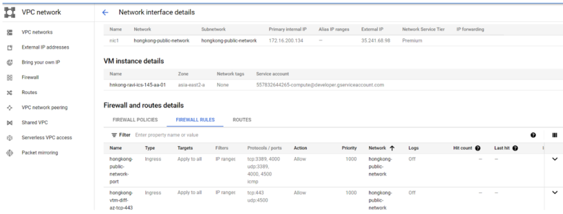
•(Optional) Click nic2. A summary page for this optional network interface appears.
Under Firewall and route details, click the Firewall Rules tab and confirm that the following firewall rules are defined.
10.The VM instance details* page, click Connect to serial console
A console monitor view (in a separate browser tab) shows the ongoing boot-up process for the instance.
11.Wait until the instance boot up is complete, and shows a screen similar to the following:
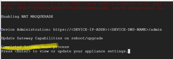
You can then complete this process by updating the Gateway details on the nSA Controller, see Completing the Configuration of the nSA Controller.
Creating a VM Instance of the Uploaded GCP Image Using a Script/Template
This section describes how to automatically create a virtual machine instance of the ICS Gateway image inside Google Cloud Platform using a script/template. You can also perform this process manually, see Creating a VM Instance of the Uploaded GCP Image Manually.
Ivanti provides YAML-based templates to create an instance of the ICS Gateway image in the following configurations:
•Two network interfaces in an existing VPC.
•Three network interfaces in an existing VPC.
Download:
https://pulsezta.blob.core.windows.net/gateway/nsa/templates/GCP/21-12-145/ivanti-ics-2-nics-existing-vpc.zip
https://pulsezta.blob.core.windows.net/gateway/nsa/templates/GCP/21-12-145/ivanti-ics-3-nics-existing-vpc.zip
•Two network interfaces in a new VPC.
•Three network interfaces in a new VPC.
Download:
https://pulsezta.blob.core.windows.net/gateway/nsa/templates/GCP/21-12-145/ivanti-ics-2-nics-new-vpc.zip
https://pulsezta.blob.core.windows.net/gateway/nsa/templates/GCP/21-12-145/ivanti-ics-3-nics-new-vpc.zip
To use a template:
1.Download the required template archive file to your local workstation.
2.Unpack the downloaded archive file to a location that is accessible from Google Cloud Platform. Each archive contains three files. These files should be present in one respective directory. For example, for the three-interface (existing VPC) version of the archive:
ivanti-ics-2-nics-existing-vpc.jinja
ivanti-ics-2-nics-existing-vpc.scheme
ivanti-ics-2-nics-existing-vpc.yaml
3.Edit the YAML file properties section to reflect your project and instance requirements, including the user_data property.
An example of an existing VPC YAML file is provided here:
|
imports: - path: ivanti-ics-3-nics-existing-vpc.jinja resources: - name: my-vm properties: project: ics-project email: [email protected] machinetype: n4-standard-4 region: asia-south1 zone: asia-south1-b image: icsgcp123 int_network: vpc-network-private-abcdef ext_network: vpc-network-public-abcdef mgmt_network: vpc-network-mgmt-abcdef int_subnetwork: vpc-asia-south1-b-ics-int-port ext_subnetwork: vpc-asia-south1-b-ics-ext-port mgmt_subnetwork: vpc-asia-south1-b-ics-mgmt-port user_data: <pulse-config><primary-dns>8.8.8.8<\primary-dns> ... type: ivanti-ics-3-nics-existing-vpc.jinja enableSecureBoot: true enableVtpm: true enableIntegrityMonitoring: false |
The following table lists all possible template properties and their meaning:
|
Property |
Description |
|---|---|
|
project |
Name of the Project |
|
|
Registered service account email address |
|
region |
The name of the region in which you want to deploy your VM instance |
|
zone |
The name of the zone in which you want to deploy your VM instance |
|
image |
Virtual machine image name |
|
machine_type |
N4-standard machine type |
|
int_network |
VPC network name for internal network |
|
ext_network |
VPC network name for external network |
|
mgmt_network |
VPC network name for management network |
|
int_subnetwork |
Subnet name for internal VPC |
|
ext_subnetwork |
Subnet name for external VPC |
|
mgmt_subnetwork |
Subnet name for management VPC |
|
user_data |
The Gateway config file downloaded. In User data, <networkConnection>v4</networkConnection> parameter can be configured as follows: •v4 : IPv4 addresses are allowed to configured (Default). |
4. Save the YAML file.
5.On the Google Cloud Platform, start a command line session from the title bar. For example:

A command line session starts.
6.Within the project folder, change to deploymentmanager folder.
7.Create a new folder and change to the new folder and copy the three script files to this folder.
8. Select the required project:
gcloud config set project <project-name>
9.Deploy the VM using the following command:
gcloud deployment-manager deployments create <vm-name> --config <yaml_file>
For example:
gcloud deployment-manager deployments create vm-gcp-123 --config ivanti-ics-3-nics-existing-vpc.yaml
10.Wait until the command completes.
11.On the VM Instances page, click on the new VM in the list of VM instances.
The VM instance details page appears for the instance.
Increasing the Disk Space in GCP
From 22.6R2 release , on fresh installation 80 GB disk space is available by default. You can modify or increase the disk size only once on fresh installation or upgrade of the ICS images, but not on rollback or factory reset images.
If the user is upgrading to 22.6R2 or later, then the disk size change from 40 GB to 80 GB have to be done prior to upgrade on Google cloud platform.
Disk Size Allocation is supported from 22.6R2 and later releases.
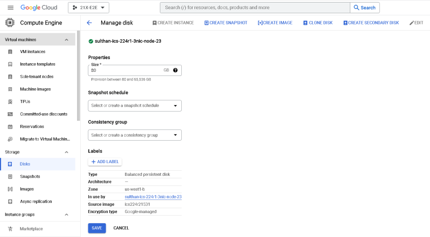
1.On the Google Cloud console, go to the Disks page. Go to Disks.
2.In the list of persistent disks in your project, click the name of the disk that you want to resize.
3.On the disk details page, click Edit. You might need to click the ⋮> More actions menu and then click Edit.
4.In the Size field, enter the new size for your disk.
5.Click Save to apply your changes to the disk.
Deploying ICS using Terraform Template
This section describes how to install terraform template and deploy ICS on GCP with 2 NICs and 3 NICs.
1.Copy variables, base_setup_tf and ics_deploy scripts to a linux m/c installed with terraform. Go to the Terraform website to install Terraform on a Linux VM of your choice at usr/local/bin.
2.Create base_setup directory and copy base_setup.tf and variables.tf to it. Customize and set the variables in variables.tf file based on the requirement.
Example: Region, AMI-id, VPC name, subnet IP address details, instance name etc.
3.cd to base_setup directory and run terraform apply.
linux# terraform apply
4.Create ics_deploy directory and copy ics_deploy and variables.tf to it
5.Run following command:
terraform apply -input=false -auto-approve -var "instance_name=gcp-test-instance-1" -var "image_name=icsgcp386"
Before running the script, user has to create an image in the GCP cloud in the name of icsgcp386 (as shown above)
Downloading Terraform Template File
To download Terraform Template zip file:
1.Log in to https://portal.ivanti.com/customer/product-downloads
2.Navigate to Security> Ivanti Connect Secure (ICS, Pulse Connect Secure) > Downloads > Pulse Secure > Pulse Connect Secure > Cloud Templates.
3.Under Current and Supported Releases, select the Template file and Download. For example, ps-ics-terraform_templates-9.1Rx_22.Rx-2.0.zip.
Ivanti Connect Secure Provisioning Parameters
Provisioning parameters are those parameters which are required during the deployment of a virtual appliance. Ivanti Connect Secure accepts the following parameters as provisioning parameters in the XML format.
<pulse-config>
<primary-dns><value></primary-dns>
<secondary-dns><value></secondary-dns>
<wins-server><value></wins-server>
<dns-domain><value></dns-domain>
<admin-username><value></admin-username>
<admin-password><value></admin-password>
<cert-common-name><value></cert-common-name>
<cert-random-text><value></cert-random-text>
<cert-organisation><value></cert-organisation>
<config-download-url><value></config-download-url>
<config-data><value></config-data>
<auth-code-license><value></auth-code-license>
<enable-license-server><value></enable-license-server>
<accept-license-agreement><value></accept-license-agreement >
<enable-rest><value></enable-rest>
<registration-code> 1grkL2Xbr </registration-code>
<registration-fqdn>auto.toad.pzt.dev.perfsec.com</registration-fqdn>
<enable-proxy>n</enable-proxy>
<proxy-host></proxy-host>
<proxy-port></proxy-port>
<proxy-username></proxy-username>
<proxy-password></proxy-password>
<register-network-interface>external</register-network-interface>
</pulse-config>
The below table depicts the details of the xml file.
|
# |
Parameter Name |
Type |
Description |
|
1 |
wins-server |
IP address |
Wins server for Ivanti Connect Secure |
|
2 |
dns-domain |
string |
DNS domain of Ivanti Connect Secure |
|
3 |
cert-common-name |
string |
Common name for the self-signed certificate generation. This certificate is used as the device certificate of Ivanti Connect Secure Random text for the self-certificate generation Organization name for the self-signed certificate generation |
|
4 |
cert-random-text |
string |
|
|
5 |
cert-organization |
string |
|
|
6 |
config-download-url |
String URL |
Http based URL where XML based Ivanti Connect Secure configuration can be found. During provisioning, Ivanti Connect Secure fetches this file and comes up with preloaded configuration. XML based configuration can be present in another VM in AWS cloud or at corporate network which is accessible for Ivanti Connect Secure through site to site VPN between AWS and corporate data center |
|
7 |
config-data |
string |
base64 encoded XML based Ivanti Connect Secure configuration |
|
8 |
auth-code-license |
string |
Authentication code that needs to be obtained from Ivanti |
|
9 |
enable-license-server |
string |
If set to ‘y’, ICS will be deployed as a License server. If set to ‘n’, ICS will be deployed as a normal server. |
|
10 |
accept-license-agreement |
string |
This value is passed to the instance for configuration at the boot time. By default, this value is set to “n”. This value must be set to “y”. |
|
11 |
enable-rest |
string |
If set to ‘y’, REST API access for the administrator user is enabled. |
- In the above list of parameters, primary dns, dns domain, admin username, admin password, cert-random name, cert-random text, cert-organization and accept-license-agreement are mandatory parameters. The other parameters are optional parameters.
- The XML parsing fails if the following characters are used in the strings:
- "
- ’
- <
- >
- &
- Ivanti Connect Secure supports zero touch provisioning. This feature can detect and assign DHCP networking settings automatically at the Ivanti Connect Secure boot up. The Ivanti Connect Secure parameters should be set to null in order to fetch the networking configuration automatically from the DHCP server.
The below table describes the new parameters that are added in the XML file and these are applicable only for nSA-managed 9.x and ICS 21.x versions.
|
Parameter |
Type |
Description |
|---|---|---|
|
registrationCode |
string |
The registration code, which is generated during the ICS gateway registration on nSA. Example: KyZR6YDL8 |
|
registrationFQDN |
string |
The registration FQDN name, which is generated during the ICS gateway registration on nSA. Example: sample.domain.com |
|
enableproxy |
string |
Default is set to n. |
|
proxyHost |
string |
The proxy server name. |
|
proxyPort |
integer |
The port number of the proxy server. Example: 8080 |
|
proxyUsername |
string |
The username of the proxy server. Example,:usr |
|
proxyPassword |
string |
The password of the proxy server. Example: pxx124 |
|
registerNetworkInterface |
string |
The interface through which the gateway registers with nSA. Example: external |