Network and Host Administration
Network and Host Administration Overview
When you install and initially set up the device, you use the serial port console to set basic network and host settings. To get started, you must use the serial console to configure these settings for the internal interface. You have the option to use the serial console to configure network and host settings for the external interface and the management interface. The network and host settings you configure with the serial port console include:
Once the internal interface has been configured, you can use the admin console Network Settings pages to modify settings for the internal interface, to enable and configure the external interface and the management interface, and to configure or manage advanced networking features, including:
•Hostname
•IPv6 addresses
•VLAN ports
•Virtual ports
•Route table entries
•Host mapping table entries
•ARP cache entries
•Neighbor discovery cache entries
•System date and time (manual configuration) or NTP
Configuring the Internal Port
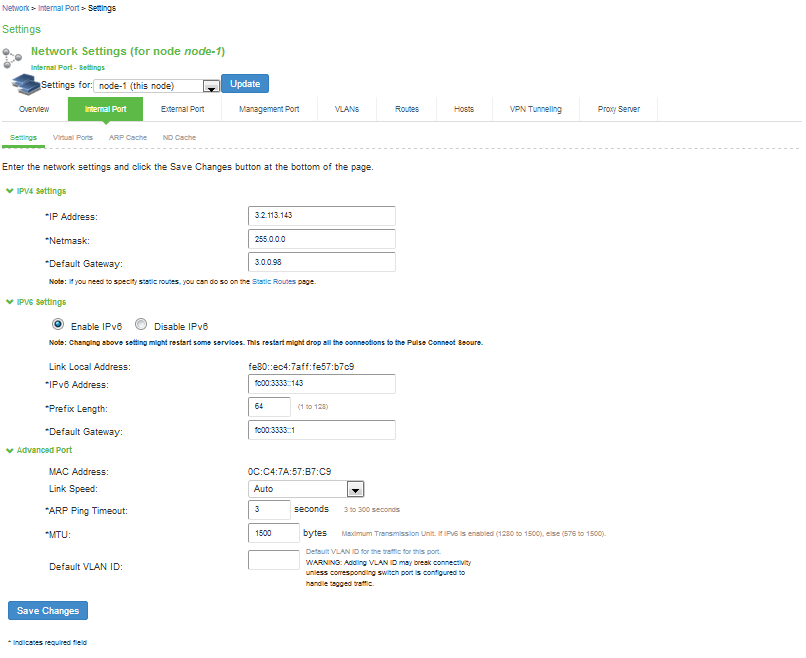
The internal port connects to the local area network (LAN). The internal port settings are configured when you run the setup wizard from the serial console as part of the installation procedure. You can use the System > Network pages to make changes to the configuration.
To modify the internal port configuration:
1.Select System > Network > Internal Port > Settings to display the configuration page.
The following figure shows the configuration page for Ivanti Connect Secure.
2.Complete the configuration as described in the following table.
3.Save your changes.
The following figure depicts the Ivanti Connect Secure Internal Port Configuration Page:
The following table lists the Internal Port Configuration Guidelines:
|
Settings |
Guidelines |
|
IPv4 Settings |
|
|
IP Address |
Assign an IP address. You must assign an IPv4 address to the internal interface. An IP address is an identifier for a computer or device on a TCP/IP network. Networks using the TCP/IP protocol route messages based on the IP address of the destination. The format of an IPv4 address is a 32-bit numeric address written as four numbers separated by periods. Each number can be 0 to 255. |
|
Netmask |
Assign a netmask. A netmask indicates which part of an IP address indicates network identification and which part indicates the host identification. For example, the IP address and netmask 10.20.30.1 255.255.255.0 (or 10.20.30.1/24) refer to all the hosts in the 10.20.30.0 subnet. The IP address and netmask 10.20.30.1 255.255.255.255 (or 10.20.30.1/32) refer to a single host. |
|
Default Gateway |
Specify the IPv4 address for the default gateway for the routing domain to which the device belongs. A gateway is the router that resides at the point of entry to the current routing domain, often called the default gateway. |
|
IPv6 Settings |
|
|
Enable IPv6 / Disable IPv6 |
Disabled by default. Enable to support access from IPv6 endpoints. When you enable IPv6, the system acquires a link local address. If you switch from enabled to disabled, the system clears the link local address. |
|
Link Local Address |
Display the autoconfigured link local address (after you have enabled and saved the IPv6 configuration). |
|
IPv6 Address |
Specify a routable IPv6 address, such as a global unicast address that your network plan has provisioned for this host and interface. Automatic configuration methods are not supported. You must specify the appropriate address manually. |
|
Prefix Length |
Specify how many of the higher order contiguous bits of the IPv6 address comprise the prefix (the network portion of the IPv6 address). The default is 64. |
|
Gateway |
Specify the IPv6 address for the default gateway for the routing domain to which the device belongs. A gateway is the router that resides at the point of entry to the current routing domain, often called the default gateway. |
|
Advanced Settings |
|
|
MAC Address |
Display the MAC address for the interface. |
|
Link Speed |
Specify the speed and duplex combination for the interface. If you run SNMP_GET and then change the Link Speed value, you must wait at least 5 minutes after submitting the change before running SNMP_GET again. |
|
ARP Ping Timeout |
(IPv4 only.) Specify how long the system should wait for responses to Address Resolution Protocol (ARP) requests before timing out. Cluster nodes send ARP requests to the gateways of other nodes to determine if they are properly communicating with one another. If you have not deployed a cluster, the system does not use this setting. If the node belongs to a cluster, the timeout interval that you specify is synchronized across the cluster. In multisite clusters, you can override this setting for the individual nodes in the cluster using options in the System > Clustering page. Use caution when changing this setting in active/passive clusters, however, because the system also uses the ARP Ping Timeout setting on the Internal tab as a failover timer for the VIP. |
|
MTU |
Specify the maximum transmission unit. If IPv6 is enabled, the valid range is 1280 to 1500. If IPv6 is not enabled, the valid range is 576 to 1500. We recommend you retain the default MTU setting (1500) unless you must change the setting for troubleshooting purposes. If the administrator sets ignore tcp mss in Advanced Client Configuration, then the TCP MSS option is ignored during the virtual adapter MTU calculation on the client side. For details, see Using the Advanced Client Configuration Feature |
|
Default VLAN ID |
(Optional) Specify the default VLAN ID for the traffic of this port. When this parameter is set, all the traffic on this interface is subsequently tagged with the set VLAN ID and also accepts only incoming traffic with the same tag. Necessary changes are required on the connected switch port to handle bi-directional tagged traffic.
If default VLAN ID is set incorrectly or the connected switch port is not configured accordingly, the interface can become unreachable. Default VLAN ID cannot be set if IPv6 is enabled. Default VLAN ID is supported in the clustered environment. In case of VMware ESXi based Virtual Appliance(VA), set the vSwitch configuration to port 4095 to allow Ivanti Connect Secure to tag the traffic. The set default VLAN ID should be added as a member in the physical port of switch and the same VLAN should be removed from native VLAN ID. |
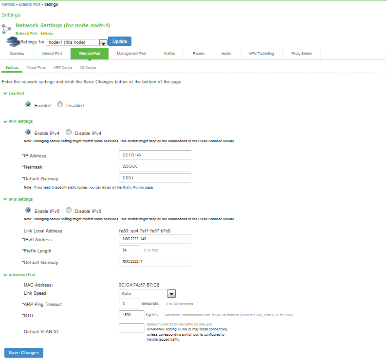
Configuring the External Port
The external port connects to the Internet. You can use the System > Network pages to configure the external port.
To configure the external port:
1.Select System > Network > External Port > Settings to display the configuration page.
The following figure shows the configuration page for Ivanti Connect Secure.
2.Complete the configuration as described in the following table.
3.Save your changes.
The following figure depicts the Ivanti Connect Secure External Port Configuration Page:
The following table lists the External Port Configuration Guidelines:
|
Settings |
Guidelines |
|
Use Port? |
|
|
Use Port? |
Select Enabled to use the port; otherwise, select Disabled. |
|
IPv4 Settings |
|
|
IP Address |
Specify an IP address. An IP address is an identifier for a computer or device on a TCP/IP network. Networks using the TCP/IP protocol route messages based on the IP address of the destination. The format of an IPv4 address is a 32-bit numeric address written as four numbers separated by periods. Each number can be 0 to 255. IPv4 Address formats as per RFC-1166 are allowed. |
|
Netmask |
Specify a netmask. A netmask indicates which part of an IP address indicates network identification and which part indicates the host identification. For example, the IP address and netmask 10.20.30.1 255.255.255.0 (or 10.20.30.1/24) refer to all the hosts in the 10.20.30.0 subnet. The IP address and netmask 10.20.30.1 255.255.255.255 (or 10.20.30.1/32) refer to a single host. |
|
Default Gateway |
Specify the IPv4 address for the default gateway for the routing domain to which the device belongs. A gateway is the router that resides at the point of entry to the current routing domain, often called the default gateway. |
|
IPv6 Settings |
|
|
Enable IPv6 / Disable IPv6 |
Disabled by default. Enable to support access from IPv6 endpoints. When you enable IPv6, the system acquires a link local address. If you switch from enabled to disabled, the system clears the link local address. |
|
Link Local Address |
Display the autoconfigured link local address (after you have enabled and saved the IPv6 configuration). |
|
IPv6 Address |
Specify a routable IPv6 address, such as a global unicast address that your network plan has provisioned for this host and interface. Automatic configuration methods are not supported. You must specify the appropriate address manually. |
|
Prefix Length |
Specify how many of the higher order contiguous bits of the IPv6 address comprise the prefix (the network portion of the IPv6 address). The default is 64. |
|
Gateway |
Specify the IPv6 address for the default gateway for the routing domain to which the device belongs. A gateway is the router that resides at the point of entry to the current routing domain, often called the default gateway. |
|
Advanced Settings |
|
|
MAC Address |
Display the MAC address for the interface. |
|
Link Speed |
Specify the speed and duplex combination for the interface. If you run SNMP_GET and then change the Link Speed value, you must wait at least 5 minutes after submitting the change before running SNMP_GET again. |
|
ARP Ping Timeout |
(IPv4 only.) Specify how long the system should wait for responses to Address Resolution Protocol (ARP) requests before timing out. Cluster nodes send ARP requests to the gateways of other nodes to determine if they are properly communicating with one another. If you have not deployed a cluster, the system does not use this setting. If the node belongs to a cluster, the timeout interval that you specify is synchronized across the cluster. In multisite clusters, you can override this setting for the individual nodes in the cluster using options in the System > Clustering page. Use caution when changing this setting in active/passive clusters, however, because the system also uses the ARP Ping Timeout setting on the Internal tab as a failover timer for the VIP. |
|
MTU |
Specify the maximum transmission unit. If IPv6 is enabled, the valid range is 1280 to 1500. If IPv6 is not enabled, the valid range is 576 to 1500. We recommend you retain the default MTU setting (1500) unless you must change the setting for troubleshooting purposes. If the administrator sets ignore-tcp-mss in Advanced Client Configuration, then the TCP MSS option is ignored during the virtual adapter MTU calculation on the client side. For details, see Using the Advanced Client Configuration Feature |
|
Default VLAN ID |
(Optional) Specify the default VLAN ID for the traffic of this port. When this parameter is set, all the traffic on this interface is subsequently tagged with the set VLAN ID and also accepts only incoming traffic with the same tag. Necessary changes are required on the connected switch port to handle bi-directional tagged traffic. If default VLAN ID is set incorrectly or the connected switch port is not configured accordingly, the interface can become unreachable. Default VLAN ID cannot be set if IPv6 is enabled. Default VLAN ID is not supported in a clustered environment. In case of VMware ESXi based Virtual Appliance(VA), set the vSwitch configuration to port 4095 to allow Ivanti Connect Secure to tag the traffic. The set default VLAN ID should be added as a member in the physical port of switch and the same VLAN should be removed from native VLAN ID. If default VLAN ID is set incorrectly or the connected switch port is not configured accordingly, the interface can become unreachable. |
Using the Internal and External Ports
The internal port, also known as the internal interface, handles all LAN requests to resources, listening for Web browsing, file browsing, authentication, and outbound mail requests. You configure the internal port by providing IP address, gateway, DNS server and domain, and MTU settings during the initial setup of Ivanti Connect Secure. You can also change them on the System > Network > Internal Port > Settings tab. Alternatively, you can deploy the appliance in dualport mode to listen for incoming Web and mail proxy SSL connections on an external port.
The external port, also known as the external interface, handles all requests from users signed into Ivanti Connect Secure from outside the customer LAN, for example, from the Internet. Before sending a packet, Ivanti Connect Secure determines if the packet is associated with a TCP connection that was initiated by a user through the external interface. If that is the case, Ivanti Connect Secure sends the packet to the external interface. All other packets go to the internal interface.
The routes that you specify for each interface apply after Ivanti Connect Secure has determined whether to use the internal or external interface. No requests are initiated by Ivanti Connect Secure from the external interface, and this interface does not accept any other connections (except ping and traceroute connections). All requests to any resource are issued from the internal interface.
If you enable the external port, then, by default, administrators may no longer sign in from an external location. You can open the external port for administrators on the Administrators > Admin Realms > RealmName > Authentication Policy > Source IP tab.
Using the Management Port
This topic describes how to configure the management port.
Management Port Overview
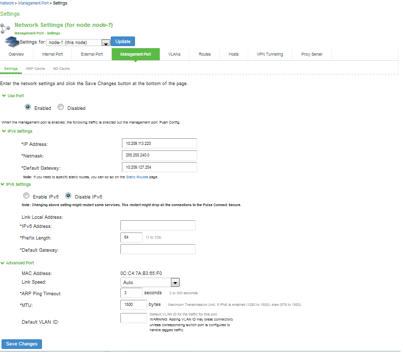
You connect the management port to an Ethernet switch or router that is part of your internal local area network (LAN) and that can connect to your network management infrastructure. When the management port is enabled, the following traffic is directed out the management port: archiving (FTP/SCP), NTP, push config, SNMP, syslog. When the management port is not enabled, that traffic uses the internal port.
On Policy Secure systems, you cannot configure the user realm configuration, the RADIUS client configuration, or the Infranet Enforcer configuration to use the management port.
Supported Platforms
The following hardware platforms are equipped with a management port:
•PSA300, PSA3000, PSA5000
•PSA7000c and PSA7000f
Configuring the Management Port
To configure the management port:
1.Select System > Network > Management Port > Settings to display the configuration page. The following figure shows the configuration page for Ivanti Connect Secure.
2.Complete the configuration as described in the following table.
3.Save your changes.
The following figure depicts the Ivanti Connect Secure Management Port Configuration Page:
The following table lists the Management Port Configuration Guidelines
|
Settings |
Guidelines |
|
Use Port? |
|
|
Use Port? |
Select Enabled to use the port; otherwise, select Disabled. |
|
IPv4 Settings |
|
|
IP Address |
Specify an IP address. An IP address is an identifier for a computer or device on a TCP/IP network. Networks using the TCP/IP protocol route messages based on the IP address of the destination. The format of an IPv4 address is a 32-bit numeric address written as four numbers separated by periods. Each number can be 0 to 255. IPv4 Address formats as per RFC-1166 are allowed. |
|
Netmask |
A netmask indicates which part of an IP address indicates network identification and which part indicates the host identification. For example, the IP address and netmask 10.20.30.1 255.255.255.0 (or 10.20.30.1/24) refer to all the hosts in the 10.20.30.0 subnet. The IP address and netmask 10.20.30.1 255.255.255.255 (or 10.20.30.1/32) refer to a single host. |
|
Default Gateway |
Specify the IPv4 address for the default gateway for the routing domain to which the device belongs. A gateway is the router that resides at the point of entry to the current routing domain, often called the default gateway. |
|
IPv6 Settings |
|
|
Enable IPv6 / Disable IPv6 |
Disabled by default. Enable to support network management traffic over IPv6 networks. When you enable IPv6, the system acquires a link local address. If you switch from enabled to disabled, the system clears the link local address. |
|
Link Local Address |
Display the autoconfigured link local address (after you have enabled and saved the IPv6 configuration). |
|
IPv6 Ad-dress |
Specify a routable IPv6 address, such as a global unicast address that your network plan has provisioned for this host and interface. Automatic configuration methods are not supported. You must specify the appropriate address manually. |
|
Prefix Length |
Specify how many of the higher-order contiguous bits of the IPv6 address com-prise the prefix (the network portion of the IPv6 address). The default is 64. |
|
Gateway |
Specify the IPv6 address for the default gateway for the routing domain to which the device belongs. A gateway is the router that resides at the point of entry to the current routing domain, often called the default gateway. |
|
Advanced Settings |
|
|
MAC Ad-dress |
Display the MAC address for the interface. |
|
Link Speed |
Specify the speed and duplex combination for the interface. If you run SNMP_GET and then change the Link Speed value, you must wait at least 5 minutes after submitting the change before running SNMP_GET again. |
|
ARP Ping Timeout |
(IPv4 only.) Specify how long the system should wait for responses to Address Resolution Protocol (ARP) requests before timing out. Cluster nodes send ARP requests to the gateways of other nodes to determine if they are properly communicating with one another. If you have not deployed a cluster, the system does not use this setting. If the node belongs to a cluster, the timeout interval that you specify is synchronized across the cluster. In multisite clusters, you can override this setting for the indi-vidual nodes in the cluster using options in the System > Clustering page. Use caution when changing this setting in active/passive clusters, however, because the system also uses the ARP Ping Timeout setting on the Internal tab as a failo-ver timer for the VIP. |
|
MTU |
Specify the maximum transmission unit. If IPv6 is enabled, the valid range is 1280 to 1500. If IPv6 is not enabled, the valid range is 576 to 1500. We recommend you retain the default MTU setting (1500) unless you must change the setting for troubleshooting purposes. |
|
Default VLAN ID |
(Optional) Specify the default VLAN ID for the traffic of this port. When this pa-rameter is set, all the traffic on this interface is subsequently tagged with the set VLAN ID and also accepts only incoming traffic with the same tag. Necessary changes are required on the connected switch port to handle bi-directional tagged traffic. If default VLAN ID is set incorrectly or the connected switch port is not config-ured accordingly, the interface can become unreachable. Default VLAN ID cannot be set if IPv6 is enabled. Default VLAN ID is not supported in a clustered environment. In case of VMware ESXi based Virtual Appliance (VA), set the vSwitch configura-tion to port 4095 to allow Ivanti Connect Secure to tag the traffic. The set default VLAN ID should be added as a member in the physical port of switch and the same VLAN should be removed from native VLAN ID. |
|
|
|
Using the Serial Console to Configure the Management Port
To configure management port network settings from the serial console:
1.Start a serial console session.
2.Select item 1, System Settings and Tools.
3.Select item 10, Configure Management port. The text indicates if the option is enabled or disabled.
4.Enter the network settings for the Management Port, as prompted.
If you enable the Management Port but neglect to configure the IP address and netmask, the port reverts to a disabled state. Also, you cannot clear Management Port settings from the serial console when the port is disabled, though you can clear them from within the admin console.
5.When prompted to accept the changes, if they are correct, enter y. Otherwise, repeat the process to correct the settings.
6.Close the serial console.
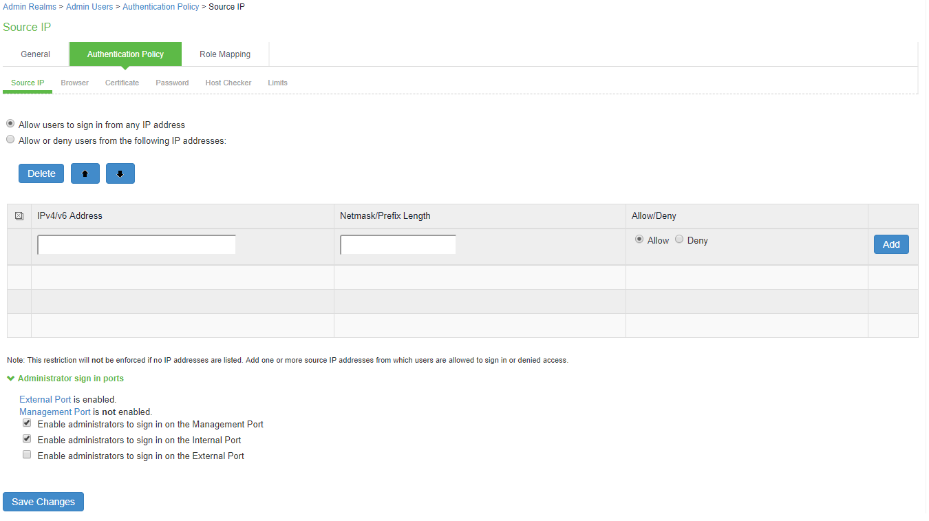
Configuring Administrator Access
You can configure the Administrators > Admin Realm > Authentication Policy > Source IP restrictions configuration to enable administrator sign-in through the management port.
You can use Administrator realms to control administrator access to system ports, including the management port.
To control administrator access to the management port:
1.Enable the management port.
2.Perform one of the following steps:
•Select Administrators > Admin Realms > Admin Users to modify the default admin users realm.
•Select Administrators > Admin Realms, then click New, to create a new administrator realm.
3.Select the Authentication Policy > Source IP.
4.Select one of the following options:
•Allow users to sign in from any IP address: Allows users to sign in from any IP address to satisfy the access management requirement.
•Allow or deny users from the following IP addresses: Specifies whether to allow or deny users access from all of the listed IP addresses, based on their settings.
To specify access from an IP address:
•Enter the IP address and netmask. IPv4 Address formats as per RFC-1166 are allowed.
•Select either Allow to allow users to sign in from the specified IP address, or Deny to prevent users from signing in from the specified IP address.
5.Select the available options to allow administrators to sign in to all available ports, to the management port or the internal port only, or to restrict them from signing in to any of the ports. In some cases, you may inadvertently limit administrative access completely. If this occurs, you can reconfigure the ports by way of the serial console.
Select from the following available options:
•Enable administrators to sign in on the management port.
•Enable administrators to sign in on the internal port.
•Enable administrators to sign in on the external port.
The following figure shows the configuration page for administrator access.
6.Click Save Changes.
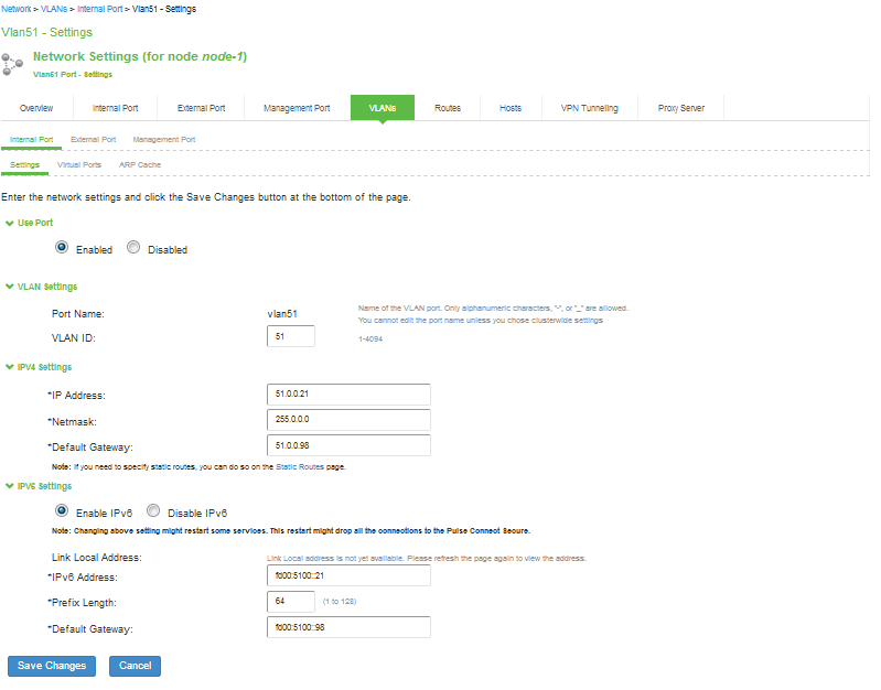
Configuring VLAN Ports
Your network design might include VLANs to provide network segmentation. When connected to a trunk port on a VLAN enabled switch, the system encounters traffic from all VLANs. This is useful for network designs with separate VLANs for separate classes of users or endpoints, and for making the system accessible from all VLANs. You can use RADIUS attributes to place different users in different network segments.
The system supports IEEE 802.1Q VLAN tagging. You must define a VLAN port for each VLAN. The internal port must be assigned to the root system and must be marked as the default VLAN. Routes to servers reachable from the VLAN interfaces must have the nexthop gateway set to the configured gateway for the VLAN interface, and must have the output port defined as the VLAN port.
When you save the configuration for a new VLAN port, the system creates two static routes by default:
•The default route for the VLAN pointing to the default gateway.
•The interface route to the directly connected network.
To configure an internal VLAN port:
1.Select System > Network > VLANs > Internal Port > New VLAN Port -Settings.
The following figure shows the configuration page for Ivanti Connect Secure.
2.Complete the configuration as described in the following table.
3.Save your changes.
The following figure depicts the Ivanti Connect Secure VLAN Port Configuration Page:
The following table lists the VLAN Port Configuration Guidelines
|
Settings |
Guidelines |
|
Use Port? |
|
|
Use Port? |
Select Enabled to use the port; otherwise, select Disabled. |
|
VLAN Settings |
|
|
Port Name |
Specify a name that is unique across all VLAN ports that you define on the system or cluster. Only alphanumeric characters, "-", or "_" are allowed. |
|
VLAN ID |
Specify a number between 1 and 4094. The VLAN ID assignment must be unique on the system. |
|
IPv4 Settings |
|
|
IP Address |
Specify an IP address and netmask combination that is from the same network as the VLAN. VLAN IP addresses must be unique. You cannot configure a VLAN to have the same network as the internal port. For example, if the internal port is 10.64.4.30/16 and you configure a VLAN as 10.64.3.30/16, you might get unpredictable results and errors. The format of an IPv4 address is a 32-bit numeric address written as four numbers separated by periods. Each number can be 0 to 255. IPv4 Address formats as per RFC-1166 are allowed. |
|
Netmask |
Specify a netmask. A netmask indicates which part of an IP address indicates network identification and which part indicates the host identification. For ex-ample, the IP address and netmask 10.20.30.1 255.255.255.0 (or 10.20.30.1/24) refer to all the hosts in the 10.20.30.0 subnet. The IP address and netmask 10.20.30.1 255.255.255.255 (or 10.20.30.1/32) refer to a single host. |
|
Default Gateway |
Specify the IPv4 address for the default gateway for the routing domain to which the device belongs. A gateway is the router that resides at the point of entry to the current routing domain, often called the default gateway. |
|
IPv6 Settings |
|
|
IPv6 Settings |
Select Enabled to use the port; otherwise, select Disabled. |
|
IPv6 Address |
Specify a routable IPv6 address, such as a global unicast address that your network plan has provisioned for this host and interface. Automatic configuration methods are not supported. You must specify the appropriate address manual-ly. |
|
Prefix Length |
Specify how many of the higher order contiguous bits of the IPv6 address com-prise the prefix (the network portion of the IPv6 address). The default is 64. |
|
Default Gateway |
Specify the IPv6 address for the default gateway for the routing domain to which the device belongs. A gateway is the router that resides at the point of entry to the current routing domain, often called the default gateway. |
- Link speed, ARP ping timeout, and MTU settings are inherited from the internal port configuration.
- To configure an external VLAN port, Select System > Network > VLANs > External Port > New VLAN Port -Settings.
- To configure a Management port, Select System > Network > VLANs > Managment Port > New VLAN Port -Settings.
Then, complete the configuration as described in the VLAN Port Configuration Guidelines table in th enext section.
Using Virtual Ports
This topic describes virtual ports.
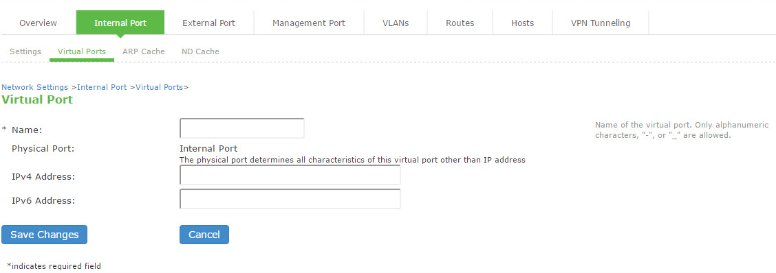
Configuring Virtual Ports
You can use virtual ports to provide different groups of users access to the same system using different IP aliases and domains.
Virtual ports are associated with the physical internal port and physical external port. The virtual port shares all of the network settings with the associated physical port, except for the IP address.
When you configure virtual ports, you in essence are creating name IP address pairs. The names and IP addresses must be unique in your network. An alias can include IPv4 addresses, IPv6 addresses, or both. However, the corresponding IP protocol must be enabled on the physical port for the addresses to take effect.
To configure a virtual port:
1.Select System > Network > PortName> Virtual Ports. PortName is Internal Port or External Port.
2.Click New Port to display the configuration page.
The following figure shows the configuration page for Ivanti Connect Secure.
3.Complete the configuration as described in the following table.
4.Save your changes.
The following figure depicts the Ivanti Connect Secure Virtual Port Configuration Page:
The following table lists the Virtual Port Configuration Guidelines:
|
Settings |
Guidelines |
|
Name |
Specify a name for the virtual port. The names and IP addresses in the virtual port configuration must be unique in your network. |
|
Physical Port |
Display the name of the physical port associated with the virtual port. The virtual port inherits link speed, ARP ping timeout, and MTU settings from the physical port configuration. |
|
IPv4 Address |
Specify an IPv4 address. An alias can include IPv4 addresses, IPv6 addresses, or both. However, the corresponding IP protocol must be enabled on the physical port for the addresses to take effect. IPv4 Address formats as per RFC-1166 are allowed. |
|
IPv6 Address |
Specify an IPv6 address. An alias can include IPv4 addresses, IPv6 addresses, or both. However, the corresponding IP protocol must be enabled on the physical port for the addresses to take effect. |
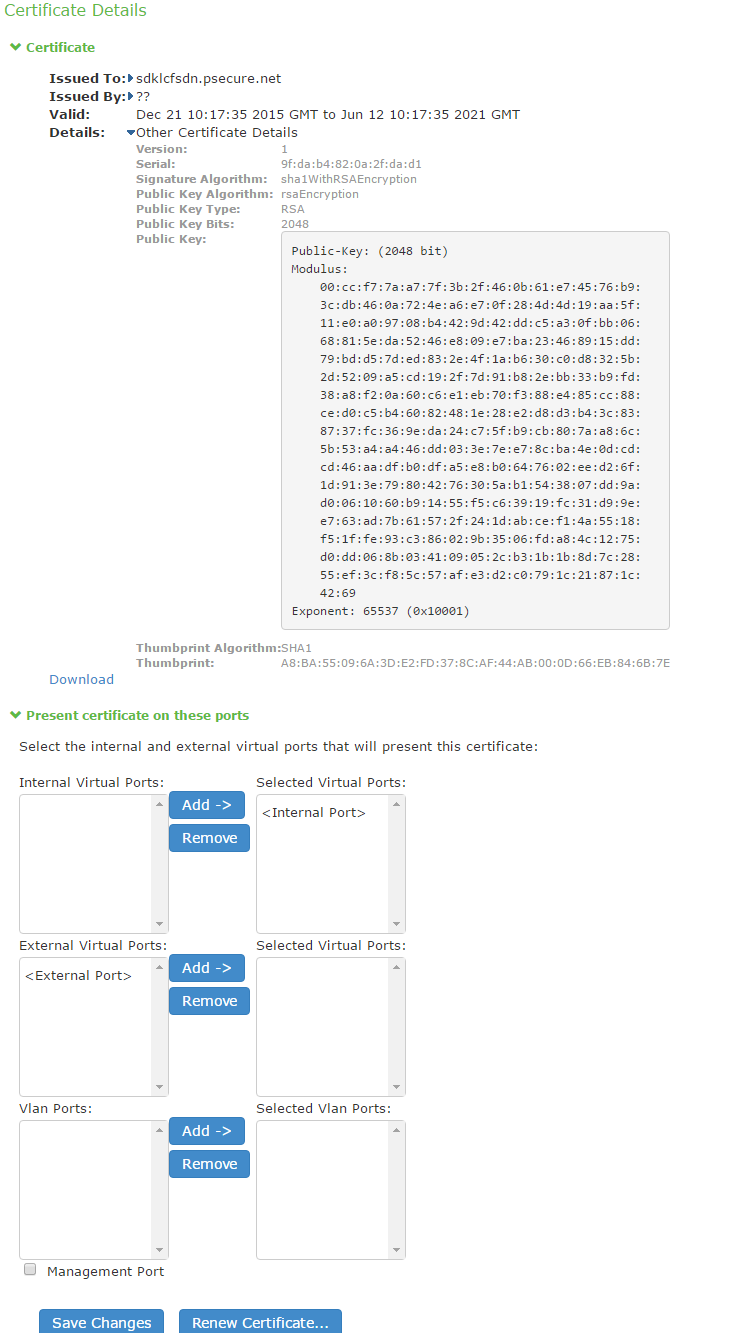
Using Device Certificates with Virtual Ports
Virtual ports can be used to create multiple fully qualified domain names for user sign-in. When a user tries to sign in using the IP address defined in a virtual port, the system presents the certificate associated with the virtual port to initiate the SSL transaction.
You can approach the digital certificate security and virtual ports implementation in either of the following ways:
•Associate all hostnames with a single certificate with this approach, you use a single wildcard certificate to validate the identity of all system hostnames, regardless of which hostname is used to sign in. A wildcard certificate includes a variable element in the domain name, making it possible for users who sign in from multiple hosts to map to the "same" domain. For example, if you create a wildcard certificate for *.yourcompany.com, the system uses the same certificate to validate its identity to users who sign in to employees.yourcompany.com as it does to users who sign into partners.yourcompany.com.
•Associate each hostname with its own certificate with this approach, you associate different hostnames with different certificates. Create a virtual port for each hostname. A virtual port activates an IP alias on a physical port. For example, you can create two virtual ports on a single appliance, mapping the first virtual port to the IP address 10.10.10.1 (sales.yourcompany.com) and the second virtual port to the IP address 10.10.10.2 (partners.yourcompany.com). Then you can associate each of these virtual ports with its own certificate, ensuring that users authenticate through different certificates.
To associate certificates with virtual ports:
1.Create virtual ports.
2.Import the device certificates.
3.Associate the device certificates with the virtual ports:
1.Select System > Configuration > Certificates > Device Certificates.
2.Click the link of the device certificate you want to configure to display the configuration page.
The following figure shows the configuration page for Ivanti Connect Secure.
3.Use the controls in the "Present certificate on these ports" section to associate ports with the certificate.
The following figure depicts the Ivanti Connect Secure Certificate Details Page:
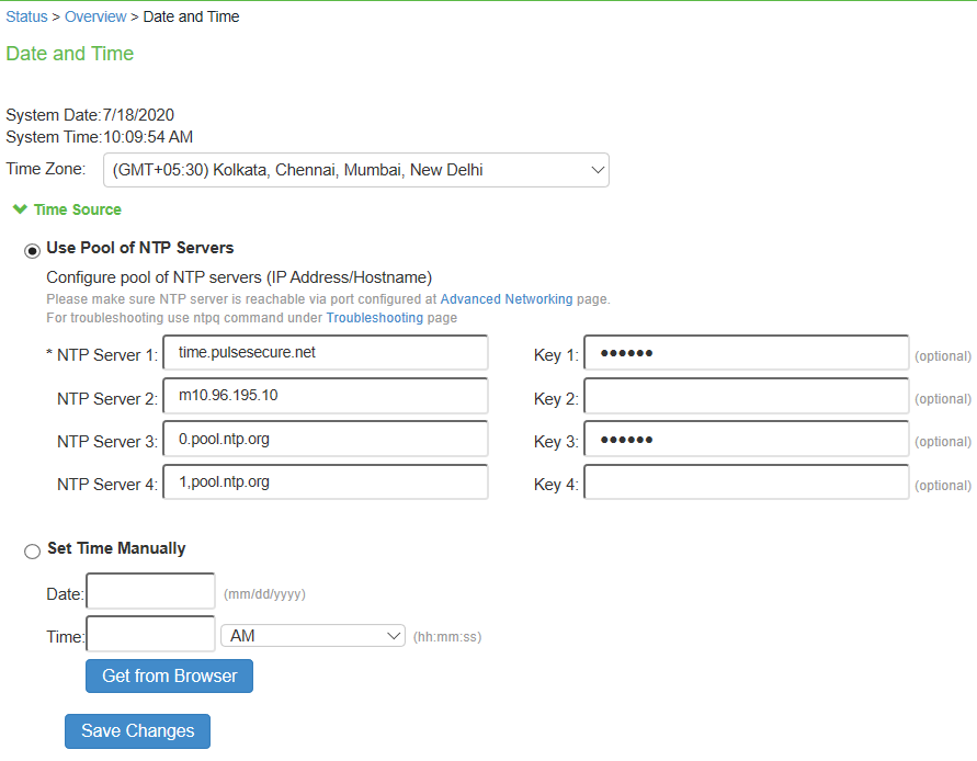
Configuring the System Date and Time
You can use the admin console to set the system date and time manually or by configuring a network time protocol (NTP) server. The system supports NTPv4, which is backwards compatible with NTPv3 and NTPv2.
BEST PRACTICE: We recommend you use NTP to synchronize the date and time clocks on all network systems. Using NTP obviates issues that might occur with cluster synchronization, network communication that uses time-sensitive protocols, such as SAML, and implementation of time-based policies, such as local authentication server account expiration. In addition, using NTP as a standard in your network rationalizes timestamps in logs, which facilitates reporting and troubleshooting.
On a VMware virtual appliance, the cockpit data may be erased each hour if the same NTP server is not defined here, on the Ivanti Connect Secure license server, and on the ESXi server.
To set the system date and time:
1.Select System > Status > Overview to display the System Status dashboard.
2.Click the System Date and Time Edit link to display the configuration page.
The following figure depicts the NTP:
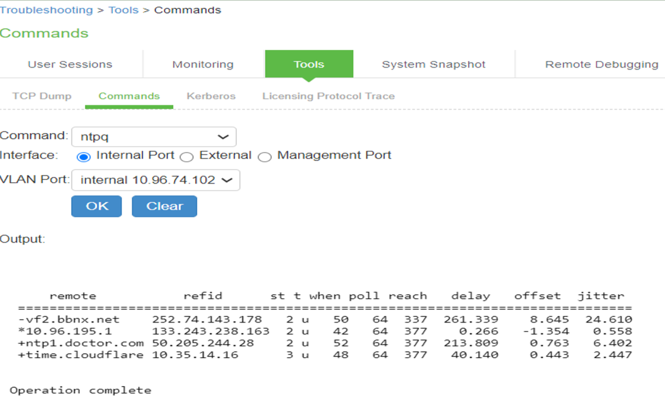
For troubleshooting, navigate to Maintenance > Troubleshooting > Tools > Commands and then use ntpq command.
The following figure depicts the ntpq Command:
3.Complete the configuration as described in the following table.
4.Save the configuration.
The following table lists the Date and Time Configuration Guidelines:
|
Settings |
Guidelines |
|
Time Zone |
Select your time zone. Selecting the appropriate time zone enables the system to automatically adjust the time for Daylight Saving Time changes. |
|
Time Source |
|
|
Use Pool of NTP Servers |
Select this option to configure pool of NTP servers. Configuring one NTP server is mandatory and keys are optional. Ivanti Connect Secure VMs deployed on VMWare ESX server will synchronize time with ESXi host. To use NTP/local time, turn off VMWare Tools Time Synchronization completely. BEST PRACTICE: It is not recommended to use only two NTP servers. If more than one NTP server is required, four NTP servers is recommended minimum. Four servers protects against one incorrect timesource. |
|
NTP Server(s) |
Specify the fully qualified domain name or IP address for the NTP server. |
|
Key(s) |
If you are using NTPv4, specify the symmetric key. The key must be pre-synchronized with the NTP server. For example, if you want to configure NIST's clock as the NTP server, you must request a key beforehand and have NIST send that key to you. The key for MD5 is in the following format: KeyNumber M KeyValue The key for SHA1 is in the following format: KeyNumber SHA1KeyValue |
|
Set Time Manually |
|
|
Date |
Specify the date. You can click Get from Browser to automatically populate the Date and Time fields. |
|
Time |
Specify the time and select AM or PM. |
Configuring Network Services
You configure DNS and WINS services when you initially configure the system with the serial console. If necessary, you can use the System > Network > Overview page to modify the configuration. You can also use this page to configure a hostname.
The network services overview page also displays the node name (if the node belongs to a cluster), and the status and interface statistics for the internal port, external port, and management port.
To configure network services:
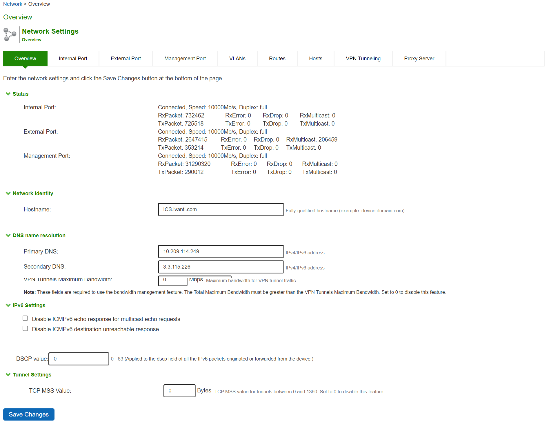
1.Select System > Network > Overview to display the configuration page.
The following figure shows the configuration page for Ivanti Connect Secure.
2.Complete the configuration as described in the following table.
3.Save your changes.
The following figure depicts the Ivanti Connect Secure Network Services Configuration Page:
The following table lists the Network Services Configuration Guidelines:
|
Settings |
Guidelines |
|
Status |
|
|
Status |
Display node name, interface statistics for the internal port, external port, and management port. |
|
Network Identity |
|
|
Hostname |
Specify a fully qualified hostname. For example, domain.company.com. The hostname cannot exceed 30 characters |
|
DNS Name Resolution |
|
|
Primary DNS |
Specify the IP address for the primary DNS server. |
|
Secondary DNS |
Specify the IP address for the secondary DNS server. |
|
DNS Domain(s) |
Specify a comma-separated list of default domains. The system searches the domains in the order they are listed. |
|
Preferred DNS Response |
This field determines what DNS requests and responses Ivanti Connect Secure will prefer to the configured DNS server. Select 'V4' if Ivanti Connect Secure is interested only in IPv4 hostname resolution requests and responses to/from the backend DNS server. Select 'Both' if Ivanti Connect Secure needs to send and receive both IPv4 and IPv6 host-name resolution requests and responses. |
|
Port for DNS Traffic |
Prior to 9.1R1 release, DNS traffic was sent over the Internal interface. Starting with 9.1R1 release, an administrator can modify the DNS setting to any physical interface namely Internal Port, External Port or Management Port. In case of a fresh installation or an upgrade, DNS port will be set to Internal port. In case of a cluster, the setting can be made node-specific as well as cluster-wide. |
|
Windows Networking |
|
|
WINS |
Specify the hostname or IP address of a local or remote Windows Internet Naming Service (WINS) server that you use to associate workstation names and locations with IP addresses. |
|
Bandwidth Management |
This feature is available only on Ivanti Connect Secure. |
|
Total Maximum Bandwidth |
Specify the maximum bandwidth for all traffic. |
|
VPN Tunnels Maximum Bandwidth |
Specify the maximum bandwidth for VPN tunnel traffic. The value of total maximum bandwidth must be greater than the value of VPN tunnels maximum bandwidth |
|
IPv6 Settings |
|
|
Disable ICMPv6 echo response for multicast echo requests |
Allows enabling or disabling of the ability to send an Echo Reply message in response to an Echo Request message sent to an IPv6 multicast or anycast address. |
|
Disable ICMPv6 destination unreachable response |
Allows enabling or disabling the Destination Unreachable message in response to a packet that cannot be delivered to its destination for reasons other than congestion. |
|
DSCP Value |
Specify the value for verifying by packet capture at client side. |
|
Tunnel Settings |
|
|
TCP MSS Value |
Set the value of the MSS which can be <= 1460 |
Configuring NTP and Other Services Traffic Over Any Physical Interface
The NTP, SNMP, Syslog, and Log archiving services are set to send the traffic through Management port by default. In case the Management port is not available, the traffic is routed through Internal port. Now, an administrator can modify the settings of NTP and other services to any physical interface.
The following procedure describes the steps to configure the ports for the services. Before you proceed, ensure the External and Management ports are enabled for use in the network settings.
To configure Service Traffic Port Options:
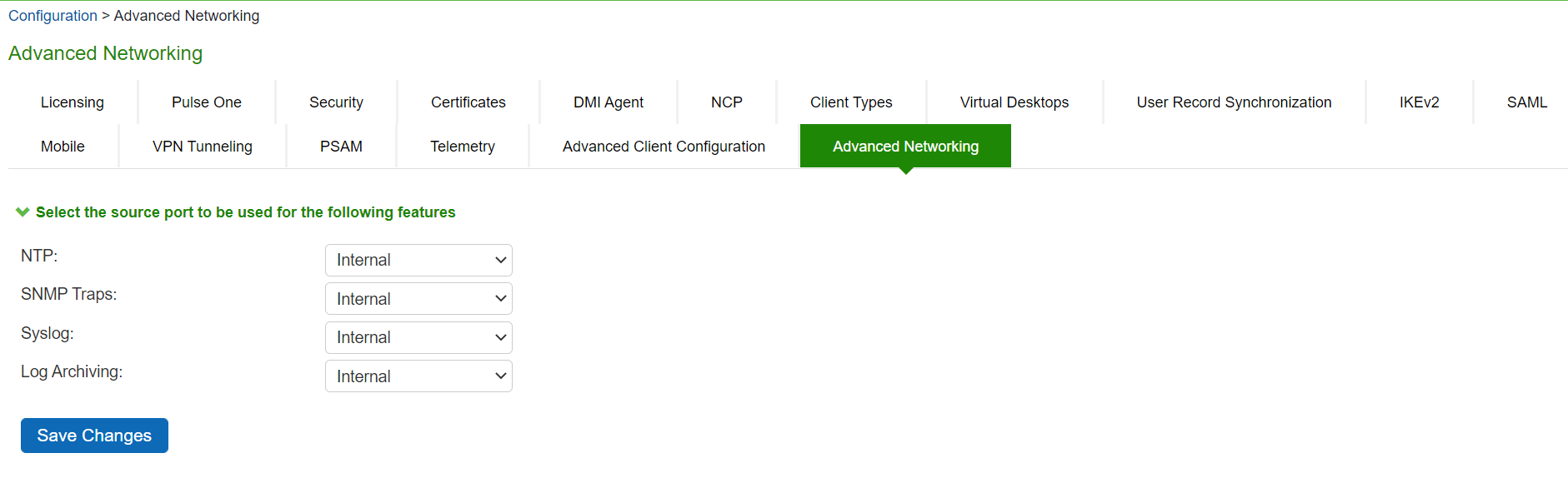
1.Select System > Configuration > Advanced Networking.
2.For the individual service, select the required port from the drop-down list.
The following figure depicts the Source Port Selection:
In a cluster environment, when a node joins the cluster, configuration of the node is replaced with the configuration of other nodes in the cluster.
Managing the Routes Table
The system populates the routes table with dynamic, auto-discovered routes. Many networks will not require changes to this routing table. If necessary, you can delete routes or add static routes.
To manage the routes table:
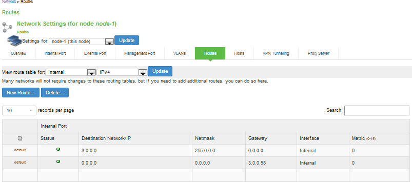
1.Select System > Network > Routes to display the routes table.
shows the routes for Ivanti Connect Secure.
2.Use the controls described in the following table to manage the routes table.
The following figure depicts the Ivanti Connect Secure Routes Table:
The following table lists the Routes Table Controls
|
Controls |
Description |
|
View route table for |
Use the controls to change the display to show the route table for internal, external, or management interfaces; and for IPv4 or IPv6 routes. |
|
Delete |
Select a row in the table and click Delete to delete a route. |
|
New Route |
Click New Route and complete the configuration to add a route to the table. You must specify a valid IP address, gateway, DNS address, and metric. The metric is a way of comparing multiple routes to establish precedence. Generally, the lower the number (from 0 to 15), the higher the precedence. Thus, a route with a metric of 2 is chosen over a route with a metric of 14. |
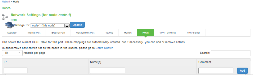
Managing the Hosts Table
In general, the system uses the configured DNS servers to resolve hostnames, but it also maintains a local hosts table that can be used for name resolution. The system populates some entries from host-IP address pair settings in your configuration. You can add host-IP address mappings for other hosts that might not be known to the DNS servers used by the system, or in cases where DNS is not reachable.
To manage the hosts table:
Select System > Network > Hosts to display the hosts table.
The following figure shows the hosts table for Ivanti Connect Secure.
Use the controls described in the following table to manage the hosts table.
The following figure depicts the Ivanti Connect Secure Hosts Table:
The following table lists Hosts Table Controls:
|
Controls |
Description |
|
Add |
Specify an IP address, hostname, and comment (a description for the benefit of system administrators) and click Add. |
|
Delete |
Click the delete icon in the last column to delete the row from the table. |
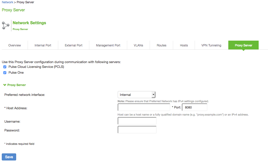
Proxy Server Configuration
This feature provides communication between PSA-Vs with Pulse Cloud Licensing Server (PCLS) and Pulse One through a configured proxy server. A new tab called Proxy Server has been added in the Network Settings to configure the same.
To configure the proxy server settings:
1.Go to System>Network>Proxy Server.
2.Select the Use Proxy Server for communicating with Pulse Cloud Licensing Service (PCLS) check box.
3.Once enabled, the proxy server settings which include Host Name and Port must be set by the admin.
4.(Optional) If your proxy server requires further authentication, enter a username and password to log in to the proxy server.
5.Click on Save.
The following figure depicts the Proxy Server:
- If the global proxy server is configured and enabled for Pulse One, the local proxy settings configured in Pulse One is disabled. Similarly, if the global proxy server is configured and enabled for PCLS, the preferred network setting is disabled in the Download Licenses page.
- The Proxy Server tab is a cluster-wide setting for both active/active and active/passive clusters. Node-specific setting is disabled.
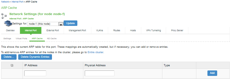
Managing the ARP Table
ARP stands for Address Resolution Protocol. In IPv4 networking, network nodes use ARP to maintain information about peer network nodes. ARP is used to associate the Layer 3 IP address with a Layer 2 MAC address of neighboring peer nodes. The system maintains an ARP table with dynamic, cached entries, and you can add static entries if necessary. The system caches dynamic entries for up to 20 minutes. Dynamic entries are deleted during a reboot. Static entries are restored after a reboot.
To manage the ARP table:
1.Select System > Network > Port > ARP Cache. Port is the Internal Port, External Port, or Management Port tab.
The following figure shows the ARP table for the internal Port for Ivanti Connect Secure.
2.Use the controls described in the following table to manage the ARP table.
The following figure depicts the Ivanti Connect Secure ARP Cache Table:
The following table lists the ARP Table Controls:
|
Controls |
Description |
|
Delete |
Select a row in the table and click Delete to delete the entry. |
|
Delete Dynamic Entries |
Delete all dynamically discovered entries. |
|
Add |
Specify an IP address, a MAC address, and click Add to add an entry. If you add an entry that has the same IP address as an existing entry, the system overwrites the existing entry with your new entry. Also note that the system does not verify the validity of MAC addresses. |
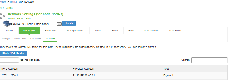
Managing the Neighbor Discovery Table
In IPv6 networking, network nodes use the Neighbor Discovery Protocol (NDP) to determine the Layer 2 MAC addresses for neighboring hosts and routers. The system uses NDP to maintain a cache of neighboring routers that are reachable and can forward packets on its behalf.
In the current release, you can view discovered neighbors or clear the entire cache, but you cannot add neighbors or delete individual entries.
To manage the neighbor discovery table:
1.Select System > Network > Port > ND Cache. Port is the Internal Port, External Port, or Management Port tab.
The following figure shows the neighbor discovery table for the internal port for Ivanti Connect Secure.
2.Use the controls described in the following table to manage the neighbor discovery table.
The following figure depicts the Ivanti Connect Secure Neighbor Discovery Table:
The following table lists the Neighbor Discovery Table Controls
|
Controls |
Description |
|
Flush NDP Entries |
Delete all dynamically discovered entries. |
Using IPv6
This topic describes support for using IPv6.
Understanding IPv6
IP version 6 (IPv6) is an Internet Protocol designed to succeed IP version 4 (IPv4). This topic provides an overview of IPv6.
About IPv6
The ongoing expansive growth of the Internet and the need to provide IP addresses to accommodate it is escalating the emergent use of a new IP protocol. IPv6 was designed to satisfy the current and anticipated near future requirements.
IPv4 is widely used throughout the world today for the Internet, intranets, and private networks. IPv6 builds upon the functionality and structure of IPv4 in many aspects, including:
•Larger address space-IPv6 addresses are 128 bits long instead of 32 bits. This expands the address space from 4 billion addresses to over 300 trillion trillion trillion addresses.
•New datagram format-The packet header is both simplified and enhanced to enable more secure and efficient routing.
•Improved fragmentation and reassembly-The maximum transmission unit (MTU) has been increased to 1280 bytes, for example.
•Transition mechanisms-Various network address translation (NAT) and tunneling mecha-nisms have been developed to support the transition to IPv6.
On February 3, 2011 Internet Assigned Numbers Authority (IANA) allotted the last block of IPv4 addresses to Regional Internet Registries (RIR), so the free pool of IPv4 addresses is now fully depleted. It is expected that in the near future Internet service providers (ISPs) will start issuing IPv6 addresses to their customers.
About IPv6 Address Types
RFC 4291, IP Version 6 Addressing Architecture describes the following types of IPv6 addresses:
•Unicast. An identifier for a single interface. A packet sent to a unicast address is delivered to the interface identified by that address.
•Anycast. An identifier for a set of interfaces. A packet sent to an anycast address is delivered to one of the interfaces identified by that address.
•Multicast. An identifier for a set of interfaces. A packet sent to a multicast address is delivered to all interfaces identified by that address.
The link-local address is a special IPv6 unicast address that is used in self-traffic and essential network communication, like Neighbor Discovery Protocol (NDP). When you enable IPv6 on a Ivanti Connect Secure interface, the system generates a link-local address that is derived from the interface MAC address.
When you configure IPv6 addresses for the system interfaces, you manually specify a routable ad-dress, such as global unicast address or an anycast address, depending on your routing implementa-tion and your system deployment. A global unicast address must be globally unique so that it can be specified globally without need for modification. An anycast address represents a service rather than a specific device. An anycast address is not unique, but instead might be configured on each device in a cluster. You are not likely to use multicast addressing with Ivanti Connect Secure.
About IPv6 Address Text Representation
All IPv6 addresses are 128 bits long, written as 8 sections of 16 bits each. They are expressed in hexa-decimal representation, so the sections range from 0 to FFFF. Sections are delimited by colons, and leading zeroes in each section may be omitted. If two or more consecutive sections have all zeroes, they can be collapsed to a double colon.
IPv6 addresses consist of 8 groups of 16-bit hexadecimal values separated by colons (:). IPv6 addresses have the following format:
aaaa:aaaa:aaaa:aaaa:aaaa:aaaa:aaaa:aaaa
Each aaaa is a 16-bit hexadecimal value, and each a is a 4-bit hexadecimal value. The following is a sam-ple IPv6 address:
2001:0DB8:0000:0000:0008:0800:200C:417A
You can omit the leading zeros of each 16-bit group, as follows:
2001:DB8:0:0:8:800:200C:417A
You can compress 16-bit groups of zeros to double colons (::) as shown in the following example, but only once per address:
2001:DB8::8:800:200C:417A
About the IPv6 Unspecified Address
In the IPv6 address space, the special "unspecified address" is 0:0:0:0:0:0:0:0. The compressed repre-sentation of the unspecified address is the double-colon (::). The unspecified address must never be assigned to a physical or virtual interface.
About the IPv6 Loopback Address
The special loopback address is the unicast address 0:0:0:0:0:0:0:1. The compressed representation of the loopback address is ::1. The loopback address may be used by a node to send an IPv6 packet to itself. It must not be assigned to a physical or virtual interface.
About IPv6 Address Prefixes
An IPv6 address prefix is a combination of an IPv6 prefix address and a prefix length used to represent a block of address space (or a network), similar to the use of an IPv4 subnet address and netmask combination to specify a subnet. An IPv6 address prefix takes the form ipv6-prefix/prefix-length. The ipv6-prefix variable follows general IPv6 addressing rules. The /prefix-length variable is a decimal value that indicates the number of contiguous, higher-order bits of the address that make up the network portion of the address. For example, 2001:DB8::/32 is an IPv6 address prefix, indicating that the first 32 bits make up the network portion of the address.
System Normalization of IPv6 Addresses
The system validates and normalizes IPv6 addresses entered by administrators. The normalized ad-dress is the address processed by the system, and it is the address that appears in logs.
The following table gives examples of how the system normalizes IPv6 address entries.
|
Example Entry |
Normalized Address |
Explanation |
|
2001:DB8:1:1::3 |
2001:DB8:1:1::3 |
An address specified in compressed format is val-idated; the system uses the compressed form as the normalized form. |
|
0:0:0::122 |
::122 |
Address is validated and normalized to com-pressed format. |
|
FF01:0:0:0:0:0:0:101 |
FF01::101 |
Address is validated and normalized to com-pressed format. |
|
2001:DB8::10.204.50.122 |
2001:DB8::ACC:327A |
Address is validated and normalized to hexadeci-mal representation. |
|
::FFFF:10.204.50.122 |
::FFFF:10.204.50.122 |
An address specified in compressed format is val-idated; the system uses the compressed form as the normalized form. |
About Neighbor Discovery Protocol
Neighbor discovery protocol (NDP) allows different nodes on the same link to advertise their exist-ence to their neighbors, and to learn about the existence of their neighbors.
Routers and hosts (nodes) use NDP messages to determine the link-layer addresses of neighbors that reside on attached links and to overwrite invalid cache entries. Hosts also use NDP to find neighboring routers that can forward packets on their behalf.
In addition, nodes use NDP to actively track the ability to reach neighbors. When a router (or the path to a router) fails, nodes actively search for alternatives to reach the destination.
IPv6 NDP corresponds to a number of the IPv4 protocols - ARP, ICMP Router Discovery, and ICMP Redirect. However, NDP provides many improvements over the IPv4 set of protocols. These im-provements address the following:
•Router discovery-How a host locates routers residing on an attached link.
•Prefix discovery-How a host discovers address prefixes for destinations residing on an at-tached link. Nodes use prefixes to distinguish between destinations that reside on an attached link and those destinations that it can reach only through a router.
•Parameter discovery-How a node learns various parameters (link parameters or Internet pa-rameters) that it places in outgoing packets.
•Address resolution-How a node uses only a destination IPv6 address to determine a link-layer address for destinations on an attached link.
•Next-hop determination-The algorithm that a node uses for mapping an IPv6 destination ad-dress into a neighbor IPv6 address (either the next router hop or the destination itself) to which it plans to send traffic for the destination.
•Neighbor unreachability detection-How a node determines that it can no longer reach a neighbor.
•Duplicate address detection-How a node determines whether an address is already in use by another node.
A router periodically multicasts a router advertisement from each of its multicast interfaces, announc-ing its availability. Hosts listen for these advertisements for address autoconfiguration and discovery of link-local addresses of the neighboring routers. When a host starts, it multicasts a router solicitation to ask for immediate advertisements.
The router discovery messages do not constitute a routing protocol. They enable hosts to discover the existence of neighboring routers, but they are not used to determine which router is best to reach a particular destination.
NDP uses the following Internet Control Message Protocol version 6 (ICMPv6) messages: router solici-tation, router advertisement, neighbor solicitation, neighbor advertisement, and redirect.
NDP for IPv6 replaces the following IPv4 protocols: Router Discovery (RDISC), Address Resolution Pro-tocol (ARP), and ICMPv4 redirect.
IPv6 Support Overview
This topic describes support for IP Version 6 (IPv6) networks.
Defining ESP Tunnel for Mixed Mode Traffic
To enable mixed mode traffic via ESP tunnel:
1.In the admin console, choose System > Configuration > VPN Tunneling.
2.In the IPv6 ESP Settings section, select the Use ESP tunnel for 6in4 and 4in6 traffic check box.
3.Click Save Changes.
To view the users connected via ESP tunnel, navigate to System > Status > Active Users.
Client Access Summary
Ivanti Connect Secure supports use of VPN Tunneling Connection Profile features to enable dual-stack endpoints to connect the Ivanti Connect Secure device and access corporate network IPv4 and IPv6 resources. The following table summarizes supported access scenarios. This is applicable to both SSL and ESP modes
The following table lists the Ivanti Connect Secure Client Access Scenarios
|
Endpoint |
Connect Se-cure Interface |
Tunnel |
Re-source |
Description of the Connection |
|
IPv4/IPv6 |
IPv4 |
IPv4-in-IPv4 |
IPv4 |
All resource access policies are supported for access to IPv4 resources. |
|
IPv6-in-IPv4 |
IPv6 |
You must configure IPv4 and IPv6 address pools in the VPN Tunneling connection profile configuration. Access to IPv6 resources using VPN Tunneling connection profiles only. |
||
|
IPv4/IPv6 |
IPv6 |
IPv4-in-IPv6 |
IPv4 |
You must configure IPv4 and IPv6 address pools in the VPN Tunneling connection profile configuration. All resource access policies are supported for access to IPv4 resources. |
|
|
||||
|
IPv6-in-IPv6 |
IPv6 |
Access to IPv6 resources using VPN Tunneling connection profiles only. |
The following table provides a summary of Ivanti Secure Access Client and system software requirements for IPv6 deployment types.
|
Connect Se-cure |
Ivanti Secure Access Client |
IPv4-in-IPv4 |
IPv4-in-IPv6 |
IPv6-in-IPv4 |
IPv6-in-IPv6 |
|
9.1Rx |
9.1Rx |
Yes |
Yes |
Yes |
Yes |
|
9.0Rx |
9.0Rx |
Yes |
Yes |
Yes |
Yes |
Network Topologies
Ivanti Connect Secure release 9.1Rx and later supports Ivanti Secure Access Client access to the IPv6 corporate network using VPN Tunneling Connection Profile features.
The role-based VPN Tunneling Connection Profile determines the IP addresses assigned to the Ivanti Secure Access Client virtual adapter. In this configuration, you must configure an IPv4 address pool. You configure an IPv6 address pool to enable access to IPv6 resources. When a client connects and is mapped to a role that includes the VPN Tunneling Connection configuration, the Ivanti Secure Access Client virtual adapter is assigned all address from each pool-both an IPv4 and IPv6 address-and a single SSL tunnel is set up. When a connection is made to the system IPv4 address, the IPv4 traffic is encapsulat-ed in the IPv4 tunnel ("4 in 4" tunneling), and the IPv6 traffic is encapsulated in the IPv4 tunnel ("6 in 4"). When a connection is made to the system IPv6 address, the IPv4 traffic is encapsulated in the IPv6 tunnel (“4 in 6"), and the IPv6 traffic is encapsulated in the IPv6 tunnel (“6 in 6").
Following IPv4 Address formats as per RFC-1166 are allowed:
tcp://*:1-1024
tcp://*:80,443
udp://10.10.10.0/24:*
icmp://10.10.10.10/255.255.255.255 10.10.10.0/24
IPv4 address should have all four subnets i.e 10.10.8.212
In this release, the DNS server used by the system must be reachable by IPv4 and must be able to re-solve both A and AAAA DNS queries. Only the VPN Tunneling Connection Profile is supported for access to IPv6 resources. All other connection options and resource policies are not supported for access to IPv6 resources.
The following figure shows a deployment topology for dual-stack-enabled endpoints that access the system over an ISP IPv4 network.
The following figure depicts the Dual Stack Endpoint Access Over ISP IPv4 Network:
The following figure shows a deployment topology for dual-stack-enabled endpoints that access the system over an ISP IPv6 network.
Dual Stack Endpoint Access Over ISP IPv6 Network:
IPv6 Support and Limitations for Ivanti Connect Secure Features
The following table summarizes IPv6 support and limitations for Ivanti Connect Secure features for Release 8.0 and later.
The following table lists the Summary of IPv6 Support
|
Feature |
Summary |
|
Ivanti Secure Access Client access |
Only the Ivanti Secure Access Client supports IPv6. The following behavior is expected for this release: Endpoints must have dual-stack enabled in order to access IPv6 resources over IPv4 networks. VPN Tunneling Connection Profiles support IPv4 and IPv6 address pools. VPN Tunneling Connection Profiles do not support ESP mode for IPv6 resource access. If a connection is configured for ESP mode, it automatically falls back to use SSL mode. On dual-stack endpoints, VPN Tunneling split tunneling rules are supported for both IPv4 and IPv6 based routes. The IPv4/IPv6 traffic allowed by a split tunneling policy is forwarded to the system in an IPv4/IPv6 tunnel. Legacy JSAM does not support IPv6. Ivanti Secure Access Client on the following platforms support VPN Tunneling connections for IPv6 resource access: Windows 8 (32 and 64 bit), Windows 10 Redstone Mac OS/X Snow Leopard, Lion, Mountain Lion, High Sierra, Mojave, Catalina Host Checker supports IPv6. Third-party Host Checker functionality is sup-ported to the extent that it is IPv6-capable. For example, the following third-party components might require endpoints to connect over IPv4: Downloading antivirus signature updates from third-party vendors. Downloading Windows Patches from Microsoft download servers. |
|
Authentication |
Active Directory (Standard Mode) - IPv4 and IPv6 based Backend servers are supported. Radius Auth Server - IPv4 and IPv6 based Backend servers are supported. |
|
DNS |
Supports both IPv4 and IPv6 DNS servers. |
|
Administrator and management access |
The internal interface and management interface can be configured with an IPv4 address or dual stack (IPv4 and IPv6). The internal interface and management interface cannot be configured with only an IPv6 address because the system uses IPv4 for the connections with network services, including AAA, DHCP, and DNS. Typically, administrators access the administrator GUI through the internal interface or management interface, but you may enable administrator access through the external interface on the Authentication > Admin Realms > Admin Users > Authentication Policy > Source IP page. |
|
Configuration through the serial console |
You cannot view or configure IPv6 network settings with the serial console. |
|
External interface configuration |
IPv4, IPv6, or both is supported. |
|
Internal interface configuration |
IPv4 or both IPv4 and IPv6 is supported. In other words, the internal interface must be configured for IPv4 connections; in addition, it may be configured for IPv6 connections. It may not be configured for IPv6 only. |
|
Management in-terface configura-tion |
IPv4 or both IPv4 and IPv6 is supported. In other words, the management interface must be configured for IPv4 connections; in addition, it may be configured for IPv6 connections. It may not be configured for IPv6 only. |
|
Virtual interface configuration |
An interface alias may include IPv4 addresses, IPv6 addresses, or both. However, the corresponding IP protocol must be enabled on the physical interface for the addresses to take effect. |
|
VLAN configura-tion |
IPv4, IPv6 or both is supported. |
|
Clustering |
Supports IPv6 configuration for active/active and active/passive clusters. The existing intra-cluster communication mechanism is preserved. The intra-cluster communication occurs over the IPv4 corporate network through the internal interfaces. |
|
License server |
IPv4 must be enabled for the "preferred network" you select for licensing protocol communication. |
|
Web server |
The implementation for IPv6 does not require reconfiguration of the system after upgrade. The Web server can listen for and accept IPv4 or IPv6 clients, and it can differentiate between them for internal purposes and for logging purposes. |
|
ActiveSync |
The implementation for IPv6 does not require reconfiguration of the system after upgrade. ActiveSync functionality is available to users connecting from IPv4 or IPv6 endpoints to an IPv4 backend server. Connection to an IPv6 backend server is not supported. |
|
Connection pro-files |
After upgrading, you can update your VPN Tunneling Connection Profile configuration to enable IPv6 address assignments to Ivanti Secure Access Client. You must configure a static IPv6 address pool. DHCPv6 is not supported. Also note that the IP address server configuration on the System > Network > VPN Tunneling page does not support filtering for IPv6 address pools. In active/active clusters, separate connection profiles need to be created with different IPv6 address pools for each node. WINS is not used in IPv6 networks; therefore, WINS settings are not applicable for connection profiles used for IPv6 access. The server-side proxy feature does not support IPv6. |
|
Resource policies |
You can configure VPN Tunneling Connection Profiles to enable access to all IPv6 resources in your corporate network; however, you cannot configure VPN Tunneling Access Control Policies to allow or deny access to particular IPv6 resources. As a workaround, we recommend you deploy firewall security to restrict access to IPv6 resources. To enable access to IPv6 resources, the DNS server used by the system must be reachable by IPv4 and must be able to resolve AAAA DNS queries. |
|
|
|
|
Core Access - Rewriter |
|
|
|
The implementation for IPv6 does not require reconfiguration of the system after upgrade. After upgrade, IPv6 endpoints can access internal IPv4 resources through the system. This applies to all system content rewriters: HTML, Java Script, Applets, VB Script, Flash, CSS, XML, PDF. You cannot configure Web Rewriting Policies for IPv6 resources. |
|
Core Access - Passthrough proxy |
|
|
|
The system passthrough proxy modes are based on hostnames or ports, not IP addresses. Therefore, the implementation for IPv6 does not require reconfiguration of the system after upgrade. Note, however, that in virtual hostname mode, your DNS server must be configured to resolve the virtual hostname to the system IP address, which can be an IPv4 or IPv6 address. Update entries in your DNS server accordingly. You cannot configure Passthrough Proxy Policies for IPv6 resources. |
|
|
Core Access - Hosted Java applets |
|
|
The implementation for IPv6 does not require reconfiguration of the system after upgrade. All hosted Java applets, including the premier Java RDP applet, work on IPv4 or IPv6 clients. You cannot configure policies that require access to hosted Java applets at IPv6 addresses. |
|
User role VPN Tunneling options |
Route Precedence: If Tunnel Route is selected, the client cannot access its local IPv6 network and IPv6 traffic is blocked, except DHCPv6, ICMPv6, and loopback traffic going to the physical adapter. If Route Monitoring is enabled, only IPv4 route monitoring is performed. If Endpoint Route is selected, the client can access its local IPv6 network. Route Monitoring should be disabled. |
|
The Multicast option is not supported for IPv6 resources. |
|
|
Role/Realm Source IP re-strictions |
You can specify IPv4 or IPv6 Source IP restrictions at both the role and the realm level. If the device is deployed behind a NAT64 device, it sees traffic coming from an IPv4 address. In this case, your Source IP restrictions should be based on the NATed IPv4 addresses. |
|
Session roaming |
You can manage session roaming across IPv6 subnets. If you enable unlimited session roaming, a session is maintained within an IPv4 network, within an IPv6 network, or from IPv4 to IPv6 and vice versa. If you configure limited session roaming, you can specify IPv4 or IPv6 subnets within which the session is maintained. However, with limited session roaming, you cannot allow sessions to roam from IPv4 to IPv6 networks, or vice versa. |
|
Logging |
The logging system can process and parse logs containing IPv6 addresses. Ivanti Connect Secure supports communication with external log systems and utilities, such as syslog, SNMP, and archiving that are reachable by IPv4 only. |
|
Network tools |
ping6 and traceroute6 were added to the admin graphical user interface console network tools page. |
IPv6 Feature Configuration Task Summary
IPv6-related features are not enabled by default. After you upgrade the system software, perform the tasks summarized in The following table describes how to make the device ready for IPv6 traffic.
The following table lists the IPv6 Feature Configuration Task Summary
|
Action |
Documentation |
|
Enable IPv6 for the external port and configure an IPv6 address. |
|
|
Enable IPv6 for the internal port and configure an IPv6 address. |
|
|
Enable IPv6 for the management port and configure an IPv6 ad-dress. |
|
|
Configure IP aliases and IPv6 addresses for virtual ports. |
|
|
Re-create a cluster deployment with IPv6 configuration for external interfaces. |
|
|
If you use source IP policies, configure them so that source IP restrictions are based on IPv6 addresses. |
|
|
Configure IPv6 address assignment for VPN Tunneling Connection Profiles. DHCPv6 is not supported. Also note that the IP address server configuration on the System > Network > VPN Tunneling page does not support filtering for IPv6 address pools. |
|
|
If you permit roaming sessions but limit to roaming within the specified subnet, configure the role session option so that the subnet is defined by netmask for IPv4 and prefix length for IPv6 networks. |
|
|
View and manage the neighbor discovery cache. You can view discovered neighbors or clear the entire cache, but you cannot add neighbors or delete individual entries. |
|
|
View IPv6 routes in the IP route table. You can view discovered IPv6 routes, but you cannot add or delete them from the route table. |
|
|
Review logs. The logging infrastructure accommodates IPv6 addresses, and you can create custom filters based on IPv6 address patterns. |
|
|
Become familiar with IPv6 network connectivity test tools, such as ping6 and traceroute6. |
Configuring SSL Options
Use the System > Configuration > Security > SSL Options page to change the default security settings. We recommend that you use the default security settings, which provide maximum security, but you may need to modify these settings if your users cannot use certain browsers or access certain Web pages.
TLS_DHE_RSA_WITH_AES_128_CBC_SHA TLS_DHE_RSA_WITH_AES_256_CBC_SHA cipher suites are supported. Both these ciphers use RSA for server authentication and ephemeral Diffie-Hellman (DHE) for key exchange. RSA server certificate is required for these ciphers. Only TLS_DHE_RSA_WITH_AES_256_CBC_SHA is available with the Accept 168-bit and greater option. In the Custom SSL Cipher configuration, TLS_DHE_RSA_WITH_AES_128_CBC_SHA is available only when AES-Medium is selected and TLS_DHE_RSA_WITH_AES_256_CBC_SHA is available only when AES-High is selected. Both ciphers are lower in priority over the other widely used cipher suites.
Enabling Granular Cipher Selection for Setting the Security Options
Granular cipher selection provides an administrator the ability to select specific ciphers and the preferred ordering of the selected ciphers. This feature also provides presets like Suite-B and PFS. There are two tabs, Inbound OpenSSL options and Outbound OpenSSL options. With this feature admins can select the ciphers that TLS/SSL connections will use. The Inbound OpenSSL options apply to all incoming connections. Outbound OpenSSL options apply to the following services:
•Rewriter
•ActiveSync
•SCEP
•Syslog
•LDAPS
FIPS Mode Settings is common for both Inbound and Outbound SSL Options.
A common cipher library has been added which can be used by both, the inbound and outbound con-nections. The outbound options are listed in a separate tab next to the inbound settings. The out-bound settings have presets for High and Medium ciphers along with custom options. There is no PFS or SuiteB presets on the outbound side. From 8.2R3 release onwards, support for preset Low has been removed and the same can be configured using Custom SSL Cipher Selection option. For the SuiteB preset to work, IVE should have ECC Device Certificate mapped to Internal or External Port. SuiteB preset does not work if the ECC Device Certificate is mapped only to virtual port.
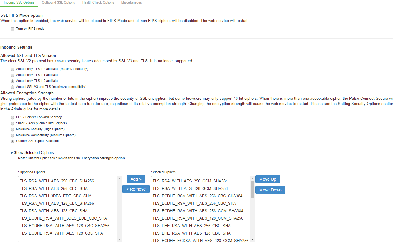
SSL FIPS Mode option
Enabling Inbound SSL Options
Only when FIPS mode is turned on, the FIPS compliant ciphers are available to be chosen from the Supported Ciphers panel. FIPS mode is editable only on the inbound option page.
To set the security options with Inbound SSL Options:
1.In the admin console, select System > Configuration > Security > Inbound SSL Options.
2.Under Allowed Encryption Strength choose Custom SSL Cipher Selection. See the following figure.
The following figure depicts the Setting Custom SSL Cipher Selections: 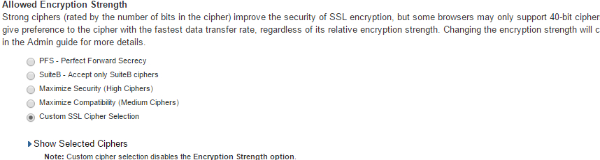
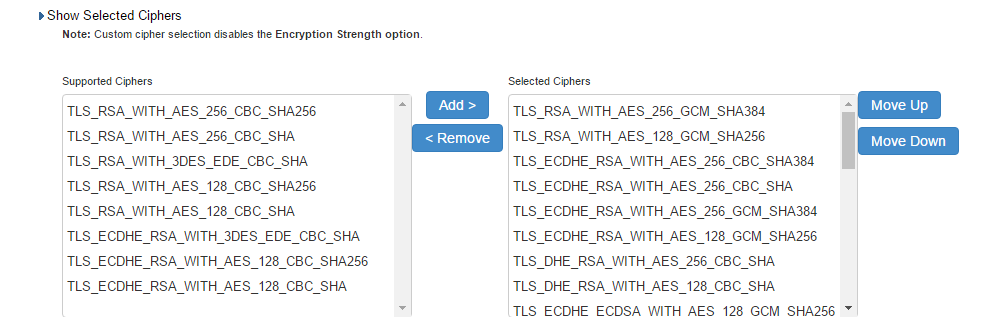
3.The two panels of Supported Ciphers and Selected Ciphers are displayed. Supported ciphers has the entire list of ciphers supported for the selected SSL or TLS version. Selected ciphers list the currently selected ciphers list. The following figure shows the two panels (Supported Ciphers and Selected Ciphers). Note that the Selected Ciphers and Supported Ciphers List will also be displayed for all Preset like PFS or SuiteB or Medium or High.
The following figure depicts the Supported Ciphers and Selected Ciphers Panels:
4.To add a cipher to be used in order to secure a connection, click on the cipher string on the left panel and then click on the Add> or double click on the cipher name in the left panel. See the following figure.
5.To remove the cipher, click on the cipher name on the right panel and then click on the <Remove but-ton or double click on the cipher name on the right side. See the following figure.
6.The selected ciphers on the right are listed in order of their priority from top to bottom. To change the priority of the ciphers, click on the cipher name and then click on Move Up to increase priority or the Move Down button to decrease the priority. See the following figure.
The following figure depicts the Setting Custom SSL Cipher Selections:
7.If you are using client certificate authentication (Connect Secure only):
•Select Enable client certificate on the external port under ActiveSync Client Certificate Configuration. See the following figure.
•Move p_ecdsa256 to the Selected Virtual Ports column.
ActiveSync Client Certificate Configuration: 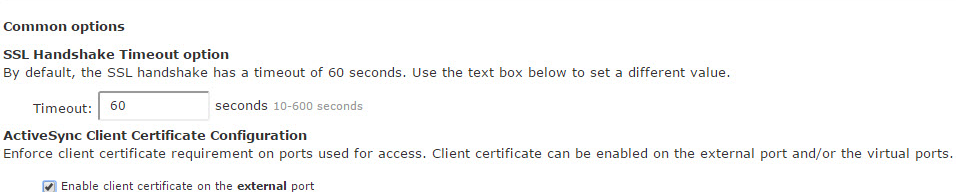
8.Click Save Changes.
A list of the custom ciphers to be used on the device's port is displayed in the order the web server will select them. Note that Suite B ciphers are listed on top. See the following table that depicts end users who now log in to external virtual port p_ecdsa256 must have at least one of the listed ciphers installed on their browser or else they cannot log in to the server.
The following figure depicts Confirming Custom Ciphers:
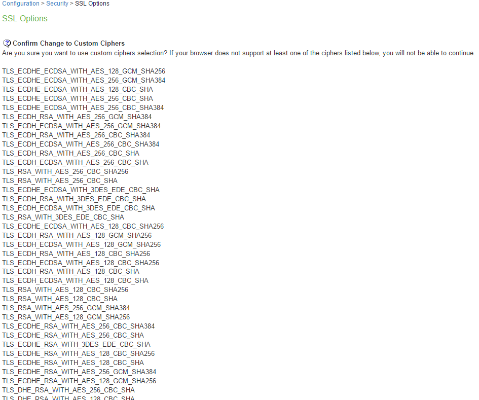
9.Click Change Allowed Encryption Strength.
- When custom ciphers are selected, there is a possibility that some ciphers are not supported by the web browser. Also, if any of ECDH/ECDSA ciphers are selected, they require ECC certificate to be mapped to the internal/external interface. If ECC certificate is not installed, admin may not be able to log in to the box. The only way to recover from this situation is to connect to the system console and select option 8 to reset the SSL settings from the console menu. Option 8 resets the SSL settings to its default. So, the previously set SSL settings are lost. This is applicable only to Inbound SSL settings.
- Ivanti Secure Access Client for Mobile does not connect to the Ivanti Connect Secure device if the ciphers selected in Inbound option are not supported by the mobile client.
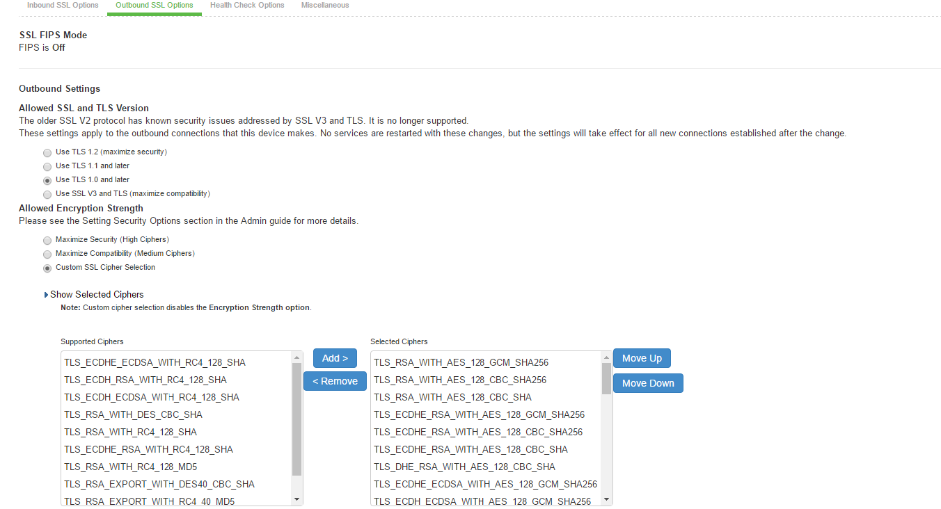
Enabling Outbound SSL Options
Only for Outbound SSL Settings, we can configure Non FIPS Ciphers when FIPS is Enabled using Custom Cipher Selection Option. Now, there are options to change different SSL/TLS versions and different encryptions in the Outbound SSL Settings. The following figure shows the Outbound SSL Settings.
The following table lists the SSL Options Configuration Guidelines:
|
Settings |
Guidelines |
|
|
SSL FIPS Mode option |
Enable FIPS mode. See the Connect Secure FIPS Level 1 Feature Guide. |
|
|
Allowed SSL and TLS Version |
Specify encryption requirements for clients. By default, the system requires SSL version 3 and TLS. The system honors this setting for all Web server traffic and all types of clients. You can require users who have older browsers that use SSL version 2 to update their browsers, or you can change this setting to allow SSL version 2, SSL version 3, and TLS. |
|
|
Allowed Encryp-tion Strength |
Accept only 128-bit and greater-The default. The system gives preference to RC4 ciphers. You can require users to have this level of encryption strength or change this default to an option compatible with the user base. Accept only 168-bit and greater-The system gives preference to 256-bit AES over 3DES. Accept 40-bit and greater-The system gives preference to RC4 ciphers. Older browsers that predate the change in the U.S. export law in year 2000 that required 40-bit cipher encryption for international export, can still use 40-bit encryption. Custom SSL Cipher Selection-Specify a combination of cipher suites for the incoming connection from the user's browser. If you select the AES/3DES option, the system gives preference to 256-bit AES over 3DES. When using 168-bit encryption, some Web browsers may still show 128-bit encryption (the gold lock on the browser status bar) even though the connection is 168-bit. This is typically a limitation of the browser's capability. If you are using the IC6500 FIPS version, you can choose High, Medium, or Low security cipher suites. AES/3DES High and AES Medium are recommended for FIPS deployment. |
|
|
Encryption Strength option |
Normally, the allowed encryption strength is enforced after an SSL session is established, so that a user connecting with a disallowed encryption strength receives a Web page describing the problem. Enable this option to prevent a browser with a weak cipher from establishing a connection. |
|
|
SSL Handshake Timeout option |
Determines how many seconds elapse before the SSL handshake times out. The default is 60 seconds. |
|
|
SSL Legacy Renegotiation Support option |
SSL and Transport Layer Security (TLS) renegotiations can be subjected to man-in-the-middle (MITM) attacks that can lead to abuse. A new TLS ex-tension (defined in RFC 5746) ties renegotiations to the TLS connections they are being performed over to prevent these kinds of attacks. The SSL Legacy Renegotiation Support option is enabled by default and allows renegotiation between clients and servers even if they do not support the new TLS extension. Disable this option to not allow renegotiations be-tween clients and servers that do not support the new TLS extension. A web server restart is required when you change the value of this option. |
|
|
ActiveSync Client Certificate Config-uration |
Use these controls to enforce client certificate requirement for activesync access on the selected ports, including virtual ports. When enabled, all ActiveSync clients must present a client authentication certificate to the system to be able to connect using ActiveSync. Non-ActiveSync access (like web browser-based access to the host, NC, JSAM, PSAM, Ivanti, WTS, IKEv2 and so forth) on the port/interface on which the ActiveSync client certificate is required might not work properly. We recommend you use a separate port or interface exclusively for ActiveSync access and then enable client certificate requirement for the port intended for ActiveSync access. |
|
SSL NDcPP Mode Option
NDcPP mode can be enabled in the Inbound tab with a check box. This status is also applied over to the Outbound tab. Turning on NDcPP automatically turns on FIPS mode and disables SSL/TLS Version TLS1.0 and below. Also, NDcPP Mode allows to choose only 16 Ciphers under Custom Encryption Strength. Turning on the NDcPP check box selects all the NDcPP ciphers by default on both, the In-bound and Outbound sides.
When the NDcPP Mode i s enabled, backend server like Windows 2008 R2 which supports the SSL/TLS Version only till TLS1.0 cannot be connected via Rewriter.
syslog-ng server
•Connection to syslog-ng server does NOT get established, since syslog-ng does not support TLSv1.1 and TLSv1.2.
rsyslog
•Supports only till TLSv1.1. So, connection would not get established, if Outbound SSL Options is set to use TLSv1.2.
- To be NDcPP compliant, NTP Update Interval needs to be limited to 60 minutes. This is to avoid the potential drift becoming too excessive.
- For incoming client certificate during client certificate authentication and for incoming server certificate during backend syslog server connection 1024-bit Key Length is not allowed in both NDcPP and FIPS Mode where as SHA1 Signature Algorithm is not allowed only in FIPS Mode and is allowed in NDcPP Mode. This restriction is not applicable for Outgoing Certificates from Ivanti Connect Secure during SSL Negotiation.
The following figure depicts the SSL NDcPP Mode Option (System > Configuration > Security > SSL Options):
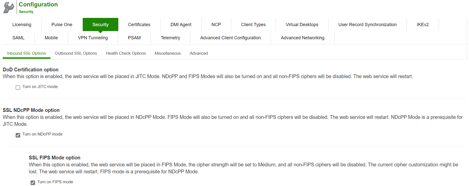
Admin Password Storage
NDcPP mandates that admin passwords needs to be scrambled with SHA2 algorithm. So, current SHA1 password scrambling is no longer supported. Password migration is done through double hashing. Existing scrambled passwords stored in the cache are scrambled again with SHA 512.
New passwords will be hashed twice: first with SHA1 and then with SHA512 and then, stored in the cache.
Inbound Settings
When the NDcPP mode is enabled, the following settings appear by default in the Inbound SSL Options page:
•The Accept only TLS 1.1 and later is enabled by default in the Allowed SSL and TLS Version settings. Only the Accept only TLS 1.1 and Accept only TLS 1.2 options can be chosen. The Accept only TLS 1.0 and later and the Accept SSL V3 and TLS (maximize compatibility) are disabled. See the following figure.
•With regards to the Allowed Encryption Strength settings the Custom SSL Cipher Selection is enabled by default with NDcPP Ciphers. All other options are disabled.
The following figure depicts the NDcPP Inbound Settings Page (System> SSL NDcPP Mode Option):
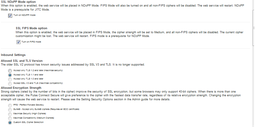
The following is a list of Selected Ciphers in the Inbound Settings with the NDcPP mode enabled:
•TLS_RSA_WITH_AES_128_CBC_SHA
•TLS_RSA_WITH_AES_256_CBC_SHA
•TLS_DHE_RSA_WITH_AES_128_CBC_SHA
•TLS_DHE_RSA_WITH_AES_256_CBC_SHA
•TLS_ECDHE_RSA_WITH_AES_128_CBC_SHA
•TLS_ECDHE_RSA_WITH_AES_256_CBC_SHA
•TLS_ECDHE_ECDSA_WITH_AES_128_CBC_SHA
•TLS_ECDHE_ECDSA_WITH_AES_256_CBC_SHA
•TLS_RSA_WITH_AES_128_CBC_SHA256
•TLS_RSA_WITH_AES_256_CBC_ SHA256
•TLS_ECDHE_ECDSA_WITH_AES_128_CBC_SHA256
•TLS_ECDHE_ECDSA_WITH_AES_256_CBC_SHA384
•TLS_ECDHE_ECDSA_WITH_AES_128_GCM_SHA256
•TLS_ECDHE_ECDSA_WITH_AES_256_GCM_SHA384
•TLS_ECDHE_RSA_WITH_AES_128_GCM_SHA256
•TLS_ECDHE_RSA_WITH_AES_256_GCM_SHA384
The following figure depicts the Selected Ciphers in the Inbound Settings with the NDcPP Mode:
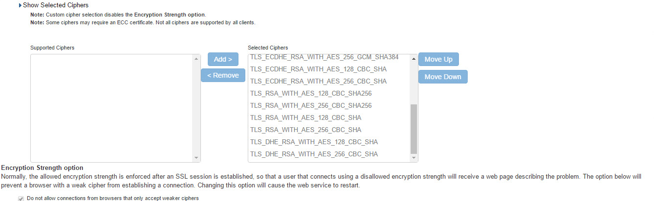
Outbound Settings
When the NDcPP mode is enabled, the following settings appear by default in the Outbound SSL Options page:
•The Accept only TLS 1.1 and later is enabled by default in the Allowed SSL and TLS Version settings. Only the Accept only TLS 1.1 and Accept only TLS 1.2 are editable. The Accept only TLS 1.0 and later and the Accept SSL V3 and TLS (maximize compatibility) are disabled.
•With regards to the Allowed Encryption Strength settings the Custom SSL Cipher Selection is enabled by default. All other options are disabled.
•Only the NDcPP ciphers configured in the Outbound SSL options settings are sent in the Outbound connections (Ivanti Connect Secure -> backend SSL).
The following figure depicts the NDcPP Outbound Settings Page (System > Configuration > Security > Outbound SSL Options):
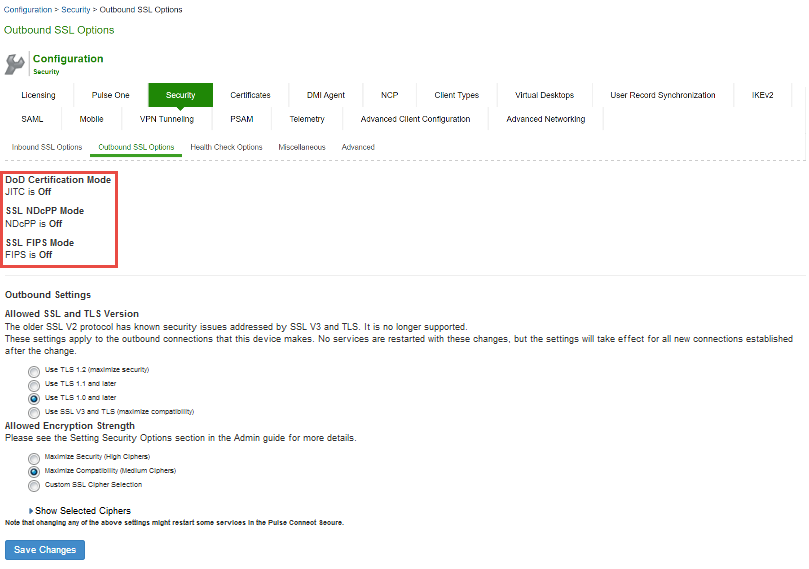
The following is a list of Selected Ciphers in the Outbound Settings with the NDcPP mode enabled:
•TLS_RSA_WITH_AES_128_CBC_SHA
•TLS_RSA_WITH_AES_256_CBC_SHA
•TLS_DHE_RSA_WITH_AES_128_CBC_SHA
•TLS_DHE_RSA_WITH_AES_256_CBC_SHA
•TLS_ECDHE_RSA_WITH_AES_128_CBC_SHA
•TLS_ECDHE_RSA_WITH_AES_256_CBC_SHA
•TLS_ECDHE_ECDSA_WITH_AES_128_CBC_SHA
•TLS_ECDHE_ECDSA_WITH_AES_256_CBC_SHA
•TLS_RSA_WITH_AES_128_CBC_SHA256
•TLS_RSA_WITH_AES_256_CBC_ SHA256
•TLS_ECDHE_ECDSA_WITH_AES_128_CBC_SHA256
•TLS_ECDHE_ECDSA_WITH_AES_256_CBC_SHA384
•TLS_ECDHE_ECDSA_WITH_AES_128_GCM_SHA256
•TLS_ECDHE_ECDSA_WITH_AES_256_GCM_SHA384
•TLS_ECDHE_RSA_WITH_AES_128_GCM_SHA256
•TLS_ECDHE_RSA_WITH_AES_256_GCM_SHA384
The following figure depicts the Selected Ciphers in the Outbound Settings with the NDcPP Mode:
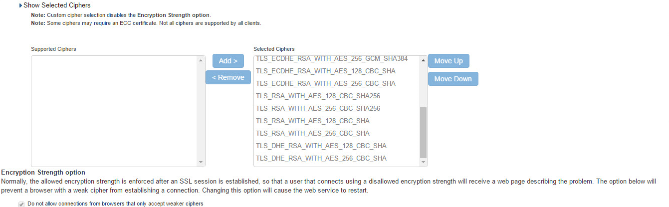
Configuring Health Check Options
You can use the System > Configuration > Security > Health Check Options page to configure the fol-lowing security options:
Enable additional information via healthcheck.cgi-This option is used by entities like load balancers to monitor the health status of the node.
To configure health check options:
1.Select System > Configuration > Security > Health Check Options to display the configuration page.
The following figure shows the configuration page:
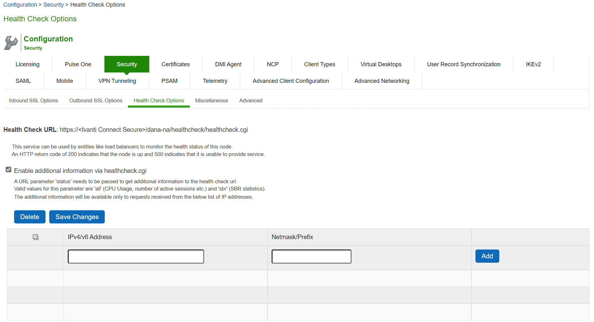
2.Select the Enable additional information via healthcheck.cgi checkbox and Save Changes. A URL pa-rameter 'status' needs to be passed to get additional information to the health check url.
For more information about parameters such as CPU usage and number of active sessions use https://<Ivanti Connect Secure>/dana-na/healthcheck/healthcheck.cgi?status=all.
For more information about SBR statistics use https://<Ivanti Connect Secure>/dana-na/healthcheck/healthcheck.cgi?status=sbr
3.Add the relevant IPv4/v6 addresses for which additional information is required to be made available, and click Add.
4.Now click Save Changes.
Configuring Miscellaneous Security Options
You can use the System > Configuration > Security > Miscellaneous page to configure the following security options:
•Persistent cookie options - You can choose whether to preserve or delete persistent cookies when a session is terminated.
•Lockout options - You can configure lockout options to protect the system from denial of ser-vice (DoS), distributed denial of service (DDoS), and password-guessing attacks.
•Last login - You can choose whether to show users the time and IP address their user ID was used to sign in.
•X-Frame-Options protection - You can choose to defend against click-jacking attacks by adding X-Frame-Option header to all the IVE generated pages. If this is not enabled, then only welcome.cgi will have this header.
•Slow Post Attack Defense - You can configure to protect against slow-post DOS attacks from non-authenticated users.
•Host Manifest Integrity Validation - You can configure to protect against integrity attacks.
•Integrity checking options - You can configure scan the system to periodically check for any integrity anomalies. If any anomaly found, information is displayed in the dashboard.
On low-end machines, a reduction in through-put may be seen. To overcome such issues, opt for scheduled scan option in off-peak hours.
To configure cookie and lockout options:
1.Select System > Configuration > Security > Miscellaneous to display the configuration page.
The following figure shows the configuration page.
2.Complete the configuration as described in the following table.
3.Save the configuration.
The following figure depicts the Miscellaneous Security Options Configuration Page:
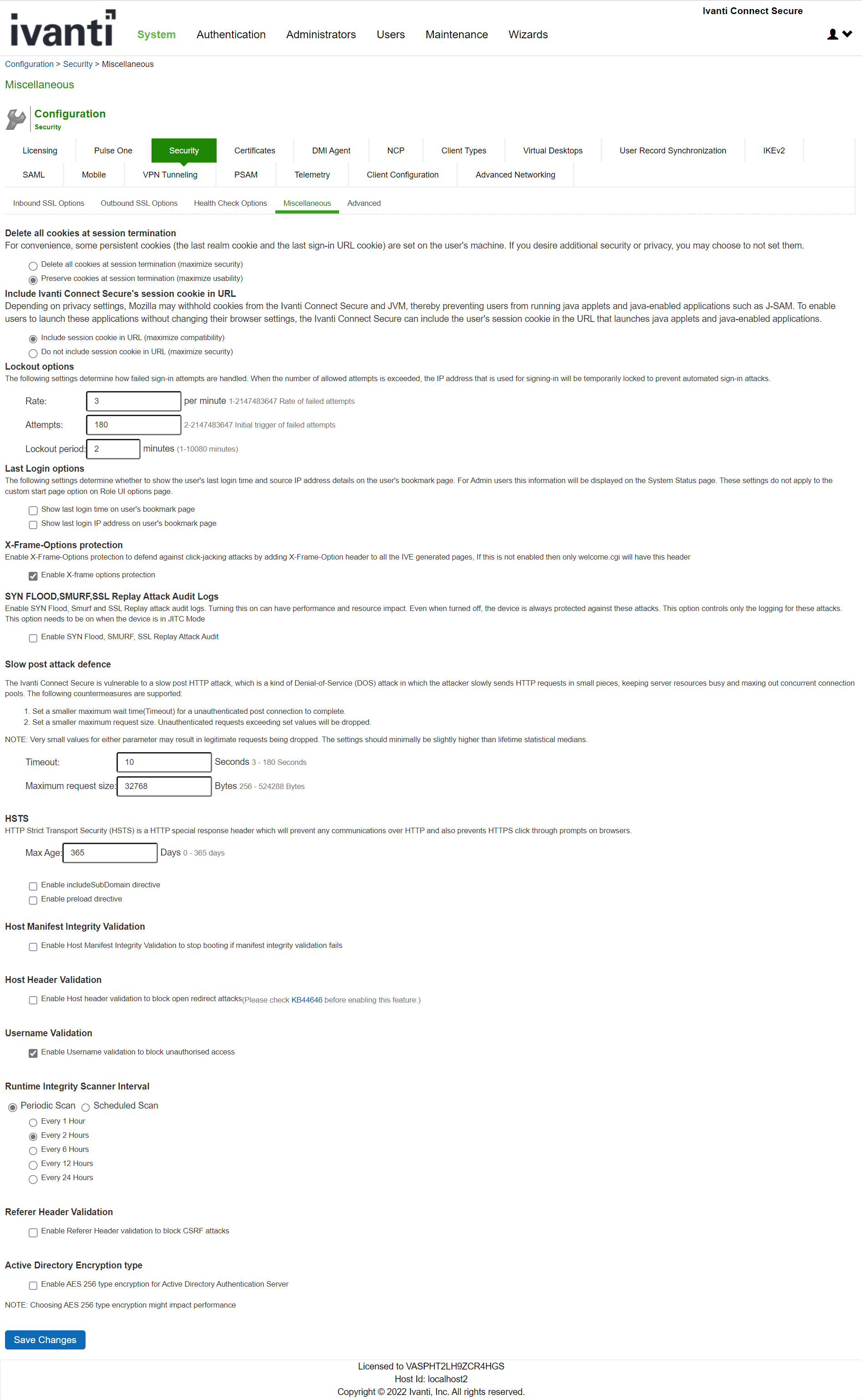
The following table lists the Miscellaneous Security Options Configuration Guidelines:
|
Settings |
Guidelines |
|
Delete all cookies at session termination |
|
|
Delete / Preserve |
For convenience, the system sets persistent cookies on the user's ma-chine to support functions such as multiple sign-in, last associated realm, and the last sign-in URL. For additional security or privacy, you can choose not to set them. |
|
Include Ivanti Connect Secure's session cookie in URL |
|
|
Include / Not In-clude |
Mozilla 1.6 and Safari may not pass cookies to the Java Virtual Machine, preventing users from running JSAM and Java applets. To support these browsers, the system can include the user session cookie in the URL that launches JSAM or a Java applet. By default, this option is enabled, but if you have concerns about exposing the cookie in the URL, you can disable this feature. |
|
Lockout options |
|
|
Rate |
Specify the number of failed sign-in attempts to allow per minute. |
|
Attempts |
Specify the maximum number of failed sign-in attempts to allow before triggering the initial lockout. The system determines the maximum ini-tial period of time (in minutes) to allow the failed sign-in attempts to occur by dividing the specified number of attempts by the rate. For ex-ample, 180 attempts divided by a rate of 3 results in an initial period of 60 minutes. If 180 or more failed sign-in attempts occur within 60 minutes or less, the system locks out the IP address being used for the failed sign-in attempt. |
|
Lockout period |
Specify the length of time (in minutes) the system must lock out the IP address. |
|
Last Login options |
|
|
Time / IP Address |
Display the day and time and IP address the user last logged in to the system. For users, this information appears on their bookmark page. For administrators, this information appears on the System Status Overview page. These settings do not apply to the custom start page option on Role UI Options page. |
|
X-Frame-Options protection |
|
|
Enable X-Frame-Options protection |
By default, the Enable X-Frame-Options is checked. If the admin does not want to have this protection, they can uncheck this option. The X-Frame-Options HTTP response header can be used to indicate whether or not a browser should be allowed to render a page in a <frame>, <iframe> or <object>. |
|
Slow Post Attack Defence |
|
|
Timeout |
By default, the POST body is received within 10 seconds. If the browser is unable to send the POST body within 10 seconds the connection is eventually dropped. (Configurable from 3 - 60Sec) |
|
Maximum Request Size |
By default, now a connection is directly rejected if it tries to POST more than 4KB in POST body (Configurable from 256 Bytes to 24 KB) |
|
HSTS |
|
|
Max Age |
Specify the maximum age for HSTS. It can be disabled by configuring max age as 0. |
|
Enable includeSub-domain directive |
Select the check box to enable/disable the includeSubdomain directive. By default, it is turned off. |
|
Enable preload di-rective |
Select the check box to enable/disable the preload directive. By default, it is turned off. |
|
Host Manifest Integrity Validation |
|
|
Enable Host Manifest Integrity Validation to stop booting if manifest integrity validation fails |
Select the check box to enforce host manifest integrity validation. By default, it is turned off. The following integrity checks are performed: Checks the SHA512 digital signature of the manifest file. Checks the SHA256 digest of each individual file entries in the manifest. If enabled and integrity check fails, admin needs to roll back to previous working package or perform factory reset. |
|
Host Header Validation |
|
|
Enable Host header validation to block open redirect attacks |
Select the check box to enforce host header validation. By default, it is turned off. When Host header validation is enabled, every http request will be validated against hostnames and IP v4/v6 addresses known to the Ivanti Connect Secure server. If match is not found, the request will be dropped and logs are recorded in admin access logs and user access logs, and a response will be sent back to client. |
|
Username Validation |
|
|
Enable Username validation to block unauthorised access |
Select the check box to enforce username validation for usage of unsupported characters. Max allowed length for username is 128 characters. |
|
Runtime Integrity Scanner Interval |
|
|
Periodic Scan
|
Select the time interval to run the integrity scanner during run time. For example: Select 2 hrs to run the integrity scanner every 2 hrs. |
|
Scheduled Scan |
Select to run integrity scanner at a specified time everyday. For example: When 13 hr 25 min is specified, the scanner runs at the same time everyday. |
|
Referer Header Validation |
|
|
Enable Referer Header validation to block CSRF attacks |
Select the check box to enable referer header validation. |
|
Active Directory Encryption type |
|
|
Enable AES 256 type encryption for Active Directory Authentication Server |
Select the check box to enable AES256 encryption type. If enabled, this option changes the encryption type to AES256 for all Active Directory Authentication Server using Kerberos Authentication protocol. This feature is applicable only for Active Directory Authentication Server using KerberOS Authentication protocol. |
Scenario Illustrating Lockout Settings Workflow
The following scenario illustrates how lockout settings work. For example, assume the following set-tings:
•Rate = 3 failed sign-in attempts per minute
•Attempts = 180 maximum allowed in initial period of 60 minutes (180/3)
•Lockout period = 2 minutes
The following sequence illustrates the effect of these settings:
1.During a period of 3 minutes, 180 failed sign-in attempts occur from the same IP address. Because the specified value for Attempts occurs in less than the allowed initial period of 60 minutes (180/3), the system locks out the IP address for 2 minutes (fourth and fifth minutes).
2.In the sixth minute, the system removes the lock on the IP address and begins maintaining the rate of 3 failed sign-in attempts/minute. In the sixth and seventh minutes, the number of failed sign-in at-tempts is 2 per minute, so the system does not lock the IP address. However, when the number of failed sign-in attempts increases to 5 in the eighth minute, which is a total of 9 failed sign-in attempts within 3 minutes, the system locks out the IP address for 2 minutes again (ninth and tenth minutes).
3.In the eleventh minute, the system removes the lock on the IP address and begins maintaining the rate of 3 failed sign-in attempts per minute again. When the rate remains below an average of 3 per minute for 60 minutes, the system returns to its initial monitoring state.
Configuring Custom HTTP Headers
Ivanti Connect Secure supports several HTTP headers, which are sent in response to the client request. There are several more headers built to improve security and prevent attacks like XSS. The Custom HTTP Headers configuration enables the administrator to add new headers that they want to enforce.
To configure custom HTTP header:
1.Select System > Configuration > Security > Advanced.
The following figure shows the configuration page.
2.In the Custom HTTP Headers section, enter the HTTP header name and the directives along with the values.
3.Click Add.
4.Multiple headers can be added or removed. After adding the headers, click Save Changes.
- Administrator should ensure the correctness of the values that they enter, as the system validation on the input values is limited.
- If the administrator configured HTTP header seems to affect the way the page is rendered or is locked out, use the console option to reset the custom HTTP header values.
The following figure depicts the Custom HTTP Headers Page:
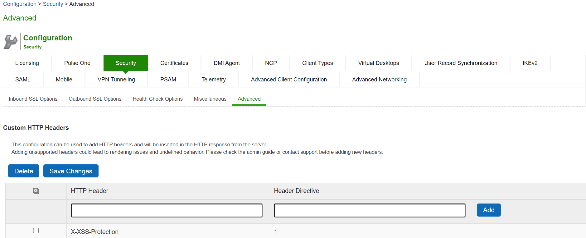
The following table lists the OWASP recommended headers:
|
Header |
Supported Browsers |
|
HPKP |
Firefox, Chrome, Opera |
|
X-XSS-Protection |
Chrome and IE |
|
X-Content-Type-Options |
Firefox, Chrome, Opera and IE |
|
Content-Security-Policy |
All major browsers |
|
X-Permitted-Cross-Domain-Policies |
Not supported |
|
Referrer-Policy |
Chrome, Firefox and Opera |
|
Expect-CT |
Chrome and Opera |
|
Feature-Policy |
Not supported |
|
HSTS |
|
|
X-Frame-Options |
|
Configuring NCP and JCP
The following types of internal protocols are used to communicate between Ivanti Connect Secure and client applications:
•Network Communications Protocol (NCP)-Standard NCP has been replaced with oNCP. Win-dows client applications, PSAM, and Terminal Ser-vices fallback to NCP if oNCP fails.
•Optimized NCP (oNCP)-Optimized NCP (oNCP) significantly improves the throughput performance of the client applications over NCP because it contains improvements to protocol efficiency, connection handling, and data compression. Windows client applications, PSAM, and Terminal Services use oNCP by default.
•Java Communications Protocol (JCP)-JCP is the Java implementation of standard NCP. The system uses JCP to communicate with Java client applications, JSAM, and the Java Content Intermediation Engine.
To set NCP options:
1.In the admin console, choose System > Configuration > NCP.
2.(Windows clients) Under NCP Auto-Select, select:
•Auto-select Enabled (recommended)-Use the oNCP by default. If you select this option, the system uses oNCP for most client/server communications and then switches to standard NCP when necessary. The system reverts to NCP if the user is running an unsupported operating system, brows-er type, or combination thereof, or if the client application fails to open a direct TCP connection to the device for any reason (for instance, the presence of a proxy, timeout, disconnect).
•Auto-select Disabled-Always use standard NCP. This option is primarily provided for backwards compatibility.
If you are using Network Connect to provide client access, we recommend that you exercise caution when employing the Auto-select Disabled option, as Mac and Linux clients cannot connect using the traditional NCP protocol. If you disable the oNCP/NCP auto-selection feature and a UDP-to oNCP/NCP fail-over occurs, the system disconnects Macintosh and Linux clients because it fails over from UDP to NCP (instead of oNCP), which does not support these users.
3.(Java clients) Under Read Connection Timeout, set the timeout interval for Java clients (15-120 seconds). If client-side secure access methods do not receive data from the system for the specified interval, they try to reestablish a connection. Note that this value does not apply to user inactivity in client applications.
4.(Windows clients) Under Idle Connection Timeout, set the idle connection interval. This timeout interval determines how long the system maintains idle connections for client-side Windows secure access methods.
5.Click Save Changes.
Using the User Record Synchronization Feature
This topic describes the user record synchronization feature.
User Record Synchronization Overview
The user record synchronization feature promotes a more consistent user experience by allowing users to retain their bookmarks and individual preferences regardless of which device they log in to.
User record synchronization relies on client-server pairings. The client is the Connect Secure device that users log in to start their remote access. Each client is associated with one primary server and one backup server to store user record data. Clients can be individual appliances or a node within a cluster.
A server in this instance is the Connect secure device that stores the user data records. Each server can be configured to replicate its user record data to one or more peer servers. Servers are identified by a user-defined logical name. The same logical name can be assigned to more than one authentication server to let you associate authentication servers of different types to the same user. For example, SA1 is an ACE authentication server with user1 who creates a bookmark to www.ivanti.com. SA2 is an Active Directory authentication server with the same user1. For the www.ivanti.com book-mark to be transferred from SA1/ACE/user1 to SA2/AD/user1 you would assign the logical name "Logi-cal1" to both the ACE server on SA1 and the Active Directory server on SA2.
Cluster VIPs cannot be used as the IP for synchronizing between clients and peers servers.
As long as the logical name is the same, the authentication servers can be different types and different server names and still be associated with a common user. The username must be the same for user record data to be synchronized across the servers. The logical authentication server (LAS) and username combination is what uniquely identifies a user record.
The following user records are synchronized between the client and server:
•Bookmarks
•Web
•File
•Terminal Services
•JSAM
•Preferences
•Persistent cookies
•Cached passwords
User session data is not synchronized. Persistent cookies, if changed, are synchronized when the user session terminates. All other modifications to the user records are synchronized immediately. User records are stored in cache on the client node prior to being pushed to the servers.
When a user logs in to a client, their data is pulled from the associated server. The pull is performed in the background and does not delay the login process. Users using browsers that do not support JavaScript must manually refresh the index page for updated bookmarks and preferences to appear. For browsers that support JavaScript, users may see a spinning progress indicator and their home page will refresh automatically with updated bookmarks and preferences.
Clients and servers need not be installed with the same system software version.
User record synchronization uses port 17425. This port number is not configurable. If you are deploying across a firewall, configure your firewall to allow traffic on this port.
To set up user record synchronization, you perform the following tasks:
1.Enable user record synchronization for each participating client and server, identify which ones are the client and which ones are the server and assign a node name to each client and server.
2.Create a shared secret that is used to authenticate the client with the server and the server to its peer servers.
3.On each server, define which clients and peers are allowed to communicate with the server.
4.On each client, define the servers that handle records for each LAS server.
When enabling this feature, you have several options to initialize the user record database. You can:
•populate the database using user records located in the cache of the client systems.
•populate the database use user records located in the cache of the server systems.
•don't pre-populate the database but populate it as users log in and out of the client system.
If you choose the last option, users may not be able to view their saved bookmarks and preferences until the next time they log in, depending on which client they log in to.
User records may not synchronize if the time clocks on the devices are not in sync. We recommend that you use the same NTP server for each node participating in user record synchronization to keep times accurately adjusted.
The user record synchronization feature will not start automatically after importing a system configuration that has this feature enabled. The workaround is to disable user record synchronization and then enable user record synchronization from the user interface after the configuration import.
Configuring the User Record Synchronization Authentication Server
To set up the authentication server you must define its logical name:
1.Select Authentication > Auth Servers.
2.Click the name of the authentication server you want assign a LAS name.
3.By assigning the authentication server a LAS name, all users that authenticate using the authentication server are associated with this LAS. In this instance, we are referring to the client nodes, not the user record synchronization server nodes.
4.Select the User Record Synchronization check box.
5.Enter a logical name to identify this server.
This allows you to share user record data across authentication servers on different Connect Secure devices. By assigning a LAS name to an authentication server, you are implicitly assigning it to all users that authenticate with that auth server. The combination of the user's login name and their LAS name uniquely identifies the user's user record across all user record synchronization servers.
6.Click Save Changes.
Configuring the User Record Synchronization Server
To set up the user record synchronization server you must define its peer nodes (optional) and the clients that can access this server.
1.Select System > Configuration > User Record Synchronization > This Server.
2.Enter the peer server's node name and IP address, then click Add. To specify more than one peer server, enter each server's node name and IP address individually and click Add. There is no limit on the number of peer servers you can add.
Data is replicated from the primary or backup server to its peer servers. If the primary is not available, user data is sent to the backup. User data is then replicated to the peer servers.
3.For each client you want synchronized with this server, enter the client's name and IP address and click Add.
Once added, peer servers will have a colored icon next to their name indicating their connection sta-tus. Node status is provided to client nodes and LAS mapping servers as well.
|
Color |
Description |
|
Green |
Connected |
|
Yel-low |
Connecting |
|
Gray |
Not connect-ed |
Configuring the User Record Synchronization Client
To set up the client, you select the primary and backup server you want this client to synchronize with:
1.Select System > Configuration > User Record Synchronization > This Client.
2.Select the LAS name you want to synchronize and enter the primary IP of the user record server that will serve the user records. If you prefer to synchronize with any available server, select Any LAS.
3.Enter the primary and optionally a backup server's IP address and then click Add.
Even if you select Any LAS, you must enter a primary server IP address.
Once added, the primary and backup servers have a colored icon next to their name indicating their connection status.
Configuring the User Record Synchronization Database
With the Database tab, you can delete inactive records from the client cache, retrieve statistics about the database, export and import the data and remove user data from the server's database.
To configure the database:
1.Select System > Configuration > User Record Synchronization > Database.
2.Select Auto-delete inactive synchronized user records from the Cache to remove inactive user records from the cache. This option does not remove user records from the user record database.
When this option is selected, the system performs a check every 15 minutes and deletes user records that meet all of the following criteria:
•There are no active user sessions associated with the user record.
•The user record does not have any custom settings, or the latest version of the user record has been synchronized with the user record database.
•The authentication server associated with the user record database does not have type "lo-cal". For example, the "System Local" auth server that is part of the default configuration has a "local" type, so any user records associated with that auth server will not be auto-deleted. However, user records associated with external authentication servers like Radius or LDAP may be deleted, depend-ing on the two prior criteria.
3.Select Auto-delete user records from the local synchronization database that have been idle for X days to permanently remove user records from the database located on the server. Enter the number of days user records must be inactive before being deleted.
In this instance, "inactive" means that no client as pulled the user record or pushed any modifications to the user record in X days.
4.Click Retrieve Statistics to display the number of records in the database. You cannot edit or view rec-ords in the database.
5.Under Export, you export user records to a file. The user records can be exported from the user rec-ord database, or from the cache. The exported file can be used to pre-populate the user record data-base on another node.
•Enter the LAS name of the user records you want to export. If you leave this field blank, all us-er records are exported. If you enter a LAS name, only user records with the entered LAS name are exported.
•To encrypt the exported data, select the Encrypt the exported data with password check box and enter the password.
•Click Export to export the user records from the specified source (cache or database). You will be prompted where to save the file.
6.Under Import, you import user records into the synchronization database. The user records can be imported from a file or from the cache. Use the Import operation to pre-populate the user record da-tabase with user records exported from another node, or with user records from the cache.
•Click Browse to locate the exported file and enter the password if the exported file was en-crypted with a password.
•Select the Override Logical Auth Servers in imported user records with check box to replace the LAS name in each imported user record with the LAS name entered.
For example, you change the LAS name, use this option to update the user records with the new name.
•Click Import.
7.Under Delete, specify which user records to permanently remove from the user record database. The options you select apply only to the user record database associated with this server:
1.Select User record with login name and Logical Auth Server to remove a specific record. The login name and LAS name together uniquely identify a user record. Select this option to remove that record (if it exists).
2.Select User records with Logical Auth Server to delete all user records with the specified LAS name.
3.Select All user records to permanently remove user records from the database on this node.
4.Click Delete.
Enabling User Record Synchronization
The first step in enabling user record synchronizing is to define the node name and the shared secret used to authenticate between the clients and the servers:
1.Select System > Configuration > User Record Synchronization > General. See the figure underneath in this section.
2.Select the Enable User Record Synchronization check box.
3.Enter a unique node name. This name is used when associating a client with a server and is different from the logical name assigned to a server. This node name is also not the same as the cluster node name.
4.Enter the shared secret and confirm it.
The shared secret is the password used to authenticate the client with its servers and the primary server with its peer servers. Use the same shared secret for all clients and servers participating in user record synchronization.
5.Select whether this node is client only or if this node acts as both a client and server.
6.Click Save Changes.
If you need to make any changes in this window at a later time, you must clear the Ena-ble User Record Synchronization check box and click Save Changes. Make your edits, select the Enable User Record Synchronization check box and save your changes.
Once you enter a name and shared secret, you cannot clear these fields.
The following figure depicts the User Record Synchronization General Settings Configuration Page:
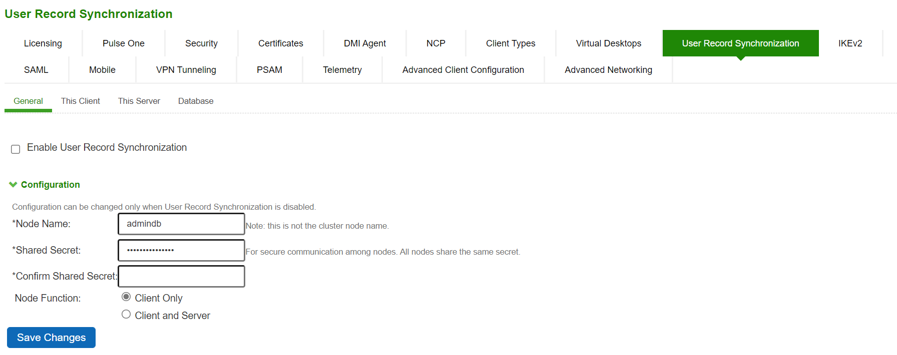
Scheduling User Record Synchronization Backup
You can configure periodic backups of the user record database. User record synchronization backup can be enabled only on a user record synchronization server.
To back up the user record database:
1.Ensure the system is set up as a user record synchronization server. See System > Configuration > User Record Synchronization.
2.Select Maintenance > Archiving > Archiving Servers.
3.Select the Archive User Record Synchronization Database check box.
4.Specify an archive schedule. Through the options, schedule archives on any combination of weekdays including weekends.
If you schedule an archival operation to occur during the hour that your system switches to Daylight Savings Time (DST) the operation may not occur as scheduled. For example, if your system is set to change to DST at 1:00 a.m. and you have scheduled an archival operation to occur at any time between 1:01 a.m. and 1:59 a.m., the operation is not accomplished, because at 1:00 a.m. the system clock is moved forward to 2:00 a.m. and the system never reaches your archival time for that date.
5.Define a specific time when you want the system to archive data or elect to archive data every hour, which produces twenty-four files with unique timestamps.
We recommend you schedule an archival operation during hours when traffic is light in order to minimize its impact to your users. The automatic archiving process compresses files and, if the system is busy, can degrade performance for users. Also, a cluster node may appear unresponsive if the system is busy with traffic and performing archiving simultaneously.
6.Provide a password if you want to encrypt system configuration or user account archives with a pass-word (optional).
7.Click Save Changes.
Using IKEv2 Security
This topic describes how to implement IKEv2 security.
IKEv2 Support Overview
This topic gives an overview of support for IKEv2 security.
Understanding IKEv2
IKE or IKEv2 (Internet Key Exchange) is the protocol used to set up a security association in the IPsec protocol suite. Microsoft Windows 7 fully supports the IKEv2 standard through Microsoft's Agile VPN functionality and can operate with a VPN gateway using these protocols. Information on IKE and IKEv2 is widely available on the Internet. It is not the intent of this guide to describe details about IKE and IKEv2.
The system supports IKEv2, enabling interoperability with clients or devices, such as smartphones, that have a standards-based IPSec VPN client.
IKEv2 clients count toward the total number of sessions. Thus, the total number of sessions = number of IKEv2 sessions + number of NCP sessions.
The system supports the following methods for authenticating IKEv2 clients:
•Machine certificate-based authentication
•Authentication using EAP methods
IKEv2 uses port 500 exclusively. Do not configure port 500 in your VPN Tunneling pro-files.
Extensible Authentication Protocol
EAP (Extensible Authentication Protocol) is an authentication framework frequently used in wireless communication. It provides functions and negotiation of authentication methods called EAP methods. Connect Secure supports the following EAP methods:
•EAP-MSCHAP-V2 (Microsoft Challenge-Handshake Authentication Protocol version 2)- a mu-tual authentication method that supports password-based user or computer authentication. During the EAP-MS-CHAP v2 authentication process, both the client and the authentication server must prove that they have knowledge of the user's password for authentication to succeed. Mutual authentica-tion is provided by including an authenticator packet returned to the client after a successful server authentication. In Connect Secure, the local authentication server and the Active Directory server sup-port EAP-MSCHAP-V2.
•EAP-MD5-Challenge - described in RFC 2284, enables an authentication server to authenticate a connection request by verifying an MD5 hash of a user's password. The server sends the client a ran-dom challenge value, and the client proves its identity by hashing the challenge and its password with MD5. EAP-MD5-Challenge is typically used on trusted networks where risk of packet sniffing or active attack are fairly low. Because of significant security vulnerabilities, EAP-MD5-Challenge is not usually used on public networks or wireless networks, because third parties can capture packets and apply dictionary attacks to identify password hashes. Because EAP-MD5-Challenge does not provide server authentication, it is vulnerable to spoofing (a third-party advertising itself as an access point).
Only the local authentication server is supported with EAP-MD5-Challenge.
IKEv2 provides a tunnel mechanism for EAP authentication; it does not perform authentication itself. Instead it proxies EAP messages from a client to the EAP server and back.
•EAP-TLS (Transport Layer Security) - a mutual authentication method that supports certificate-based authentication. EAP-Transport Layer Security Uses the handshake protocol in TLS. During the EAP-TLS authentication process, both client and the authentication server authenticate each other us-ing digital certificates. client generates a pre-master secret key by encrypting a random number with the authentication server's public key and sends it to the authentication server. Both client and au-thentication server use the pre-master secret key to generate the same master secret key. EAP-TLS is considered to be one of the most secure EAP standards available. The requirement for a client-side certificate is what gives EAP-TLS its authentication strength.
Machine Certificate-Based Authentication
The system supports IKEv2 authentication using machine certificates. Note that only certificate au-thentication server on Connect Secure supports machine certificate authentication of IKEv2 clients. When using machine certificates for authentication, it is not necessary to configure the Realm/Protocol Set Mapping section under System > Configuration > IKEv2.
Client Requirements
Your IKEv2 client should support the following requirements to work with Connect Secure:
•Ability to establish IPsec Security Associations in Tunnel mode (RFC 4301).
•Ability to utilize the AES 128-bit encryption function (RFC 3602).
•Ability to utilize the SHA-1 hashing function (RFC 2404).
•Ability to utilize Diffie-Hellman Perfect Forward Secrecy in "Group 2" mode (RFC 2409).
•Ability to utilize IPSec Dead Peer Detection (RFC 3706).
•Ability to utilize the MD5 hashing function (RFC 1321).
•Ability to handle Internal Address on a Remote Network utilizing CFG_REQUEST-CFG_REPLY exchange.
Optional but recommended requirements include:
•Ability to adjust the Maximum Segment Size of TCP packets entering the VPN tunnel (RFC 4459).
•Ability to reset the "Don't Fragment" flag on packets (RFC 791).
•Ability to fragment IP packets prior to encryption (RFC 4459).
In addition, your client must support certificate authentication and ESP/SHA1.
Supported Features
The following features are unavailable to the end user since you are using a third-party client that are neither controlled nor configured by Ivanti.
•Host Checker
•Idle timeout notifications
•Upload Logs
•Route monitoring feature of split tunnel
•Windows interactive user logon options
•Session startup scripts
•NCP tunnel mode
•DNS search order
•Proxy server settings
The following table outlines the behavior of the Network Connect client and the IKEv2 client for certain split tunnel options.
The table lists the Split Tunnel Operations with IKEv2 and Network Connect Clients:
|
Option |
IKEv2 Client |
Network Connect Client |
|
Disable split tunnel mode |
Resource-through tunnel Internet-through tunnel local subnet (client)-through physical adapter |
Internet-through tunnel local subnet (client)-through tunnel Resource-through tunnel |
|
Enable split tunnel mode |
Resource—through tunnel Internet—through tunnel but fails because the resource is not in split tunnel configuration. local subnet (client)—through physical adapt |
Internet—through physical adapter local subnet (client)—through physical adapter |
|
Allow local access subnet |
Resource-through tunnel Internet-through tunnel local subnet (client)- through physical adapter (same as disable split tunnel mode) |
Internet & other traffic—through tunnel local subnet (client)—through physical adapter |
|
Enable split tunnel mode with route monitor (NC pro-prietary) |
Resource—through tunnel Internet—through tunnel but fails because the resource is not in split tunnel configuration. local subnet (client)— through physical adapter Note: route table delete is not monitored. |
Resource—through tunnel Internet—through physical adapter local subnet (client)—through physical adapter route table delete is monitored |
|
Enable ST with Allow local access subnet |
Resource—through tunnel Internet —through tunnel but fails because the resource is not in split tunnel configuration. local subnet (client)— through physical adapter |
Resource—through tunnel Internet—through physical adapter local subnet (client)—through physical adapter |
The table below explains the limitations and supported configurations for different IKEv2 clients to work with Ivanti Connect Secure configured for different IKEv2 authentication:
The following table lists the Limitations and Supported Configurations for Different IKEv2 Clients:
|
Comparison Pa-rameter |
Windows Desktop/Laptop |
Windows Mobile Phone |
Linux Cli-ent |
iOS Client |
MAC OS Client |
|||
|
Client Version |
Win-dows10-Native Client |
Win-dows8.1-Native Client |
Windows7-Native Client |
Win-dows10 Mobile |
Win-dows8.1 Mobile |
Strong-swan5.4.0 |
iOS 9.X and above |
macOS Si-erra version 10.12 |
|
AES128/SHA1 Data Encryption Configuration |
Supports only Optional Encryption (connect even if no encryption) Configuration |
Supports only Optional Encryption (connect even if no encryption) Configuration |
Supports only Optional Encryption (connect even if no encryption) Configuration |
Supported |
Not Supported |
Supported |
Supported (this can be configured in the child SA Params in the profile). |
Supported |
|
AES256/SHA1 Data Encryption Configuration |
Supports all 3 Data Encryption Configuration Optional Encryption (connect even if no encryption Require Encryption (disconnect if server declines) • Maximum Strength Encryption (disconnect if server declines) |
Supports all 3 Data Encryption Configuration Optional Encryption (connect even if no encryption Require Encryption (disconnect if server declines Maximum Strength Encryption (disconnect if server declines) |
Supports 2 Data Encryption Configuration Optional Encryption (connect even if no encryption • Maximum Strength Encryption (disconnect if server declines) Here Optional Encryption (connect even if no encryption) is not Supported |
Supported |
Supported |
Supported |
Supported (this can be configured in the child SA Params in the profile). |
Not Supported |
|
AES256/SHA256 Data Encryption Configuration |
Not Sup-ported |
Not Sup-ported |
Not Supported |
Not Sup-ported |
Not Sup-ported |
Support-ed |
Supported |
Supported |
|
CA or CA Chain |
Need to Import Ivanti Connect Secure Device Certificate CA in Trusted Root Certificate Authorities Under Computer Account Certificate Store. Ivanti Connect Secure Device CertificateSub CA(s) Should be Imported in Intermediate Certificate Authorities Under Computer Account Certificate Store. |
Need to Import Ivanti Connect Secure Device Certificate CA in Trusted Root Certificate Authorities Under Computer Account Certificate Store. Ivanti Connect Secure Device CertificateSub CA(s) Should be Imported in Intermediate Certificate Authorities Under Computer Account Certificate Store |
Need to Import • Ivanti Connect Secure Device Certificate CA in Trusted Root Certificate Authorities Under Computer Account Certificate Store. • Ivanti Connect Secure Device CertificateSub CA(s) Should be Imported in Intermediate Certificate Authorities Under Computer Account Certificate Store |
Need to Import • Ivanti Connect Secure Device Certificate CA in Trusted Root Certificate Authorities Under Computer Account Certificate Store. • Ivanti Connect Secure Device CertificateSub CA(s) Should be Imported in Intermediate Certificate Authorities Under Computer Account Certificate Store |
Need to Import • Ivanti Connect Secure Device Certificate CA in Trusted Root Certificate Authorities Under Computer Account Certificate Store. • Ivanti Connect Secure Device CertificateSub CA(s) Should be Imported in Intermediate Certificate Authorities Under Computer Account Certificate Store |
Need to Import Ivanti Connect Secure Device Certificate CA and SubCA(s) should be place in cacert directory in pem or cer format. |
Need to Import Ivanti Connect Secure Device Certificate CA / Sub CA(s) Should be Installed through a profile. |
Need to Import Ivanti Connect Secure Device Certificate CA and SubCA(s) should be placed in System > Certificates Key Chain |
|
Client Version |
Windows10-Native Client |
Windows8.1-Native Client |
Windows7-Native Client |
Windows10 Mobile |
Windows8.1 Mobile |
Strongswan5.4.0 |
iOS 9.X and above |
macOS Sierra version 10.12 |
|
Certificate EKU Extension for EAP-TLS |
Client Certificate should have clientAuth(1.3.6.1.5.5.7.3.2)EKU Extension mandato-rily. Op-tionally Certifi-cates can have Secure Email (1.3.6.1.5.5.7.3.4) or Encrypt-ing File System (1.3.6.1.4.1.311.10.3.4) or serv-erAuth(1.3.6.1.5.5.7.3.1) |
Client Cer-tificate should have clientAuth(1.3.6.1.5.5.7.3.2)EKU Extension mandatori-ly. Optional-ly Certifi-cates can have Secure Email (1.3.6.1.5.5.7.3.4) or Encrypting File System (1.3.6.1.4.1.311.10.3.4) or serv-erAuth(1.3.6.1.5.5.7.3.1) |
Client Certificate should have clientAuth(1.3.6.1.5.5.7.3.2)EKU Extension mandatorily. Op-tionally Certifi-cates can have Secure Email (1.3.6.1.5.5.7.3.4) or Encrypting File System (1.3.6.1.4.1.311.10.3.4) or serv-erAuth(1.3.6.1.5.5.7.3.1) |
Client Cer-tificate should have clientAuth(1.3.6.1.5.5.7.3.2)EKU Exten-sion man-datorily. Optionally Certificates can have Secure Email (1.3.6.1.5.5.7.3.4) or Encrypting File System (1.3.6.1.4.1.311.10.3.4) or serv-erAuth(1.3.6.1.5.5.7.3.1) |
Client Cer-tificate should have clientAuth(1.3.6.1.5.5.7.3.2)EKU Exten-sion man-datorily. Optionally Certificates can have Secure Email (1.3.6.1.5.5.7.3.4) or Encrypting File System (1.3.6.1.4.1.311.10.3.4) or serv-erAuth(1.3.6.1.5.5.7.3.1) |
Certificate should have clientAuth(1.3.6.1.5.5.7.3.2)EKU Extension mandatorily. Optionally Certificates can have Secure Email (1.3.6.1.5.5.7.3.4) or serverAuth(1.3.6.1.5.5.7.3.1) Note: Microsoft Encrypting File System (1.3.6.1.4.1.311.10.3.4) EKU Extension is not Supported |
Client Certificate should haveclientAuth(1.3.6.1.5.5.7.3.2)EKU Extension mandatorily. Optionally Certificates can have Secure Email (1.3.6.1.5.5.7.3.4) or Encrypting File System (1.3.6.1.4.1.311.10.3.4) or serverAuth(1.3.6.1.5.5.7.3.1 |
Client Certificate should have clientAuth(1.3.6.1.5.5.7.3.2) EKU Extension mandatorily. Optionally Certificates can have Secure Email (1.3.6.1.5.5.7.3.4) or Encrypting File System (1.3.6.1.4.1.311.10.3.4) or serverAuth(1.3.6.1.5.5.7.3.1) |
|
NDcPP Mode |
Support-ed |
Not Supported |
Not Supported |
Supported |
Not Sup-ported |
Support-ed |
Supported |
Not Sup-ported |
|
TLS Version |
Supports SSLv3, TLS1.0, TLS1.1 and TLS1.2 |
Supports only SSLv3 and TLS1.0 |
Supports only SSLv3 and TLS1.0 |
Supports SSLv3, TLS1.0, TLS1.1 and TLS1.2 |
Supports only SSLv3 and TLS1.0 |
Supports SSLv3, TLS1.0, TLS1.1 and TLS1.2 |
Supports SSLv3, TLS1.0, TLS1.1 and TLS1.2 |
Supports only TLS1.0 |
|
SuiteB Encryption |
Not Supported |
Not Supported |
Not Supported |
Not Supported |
Not Supported |
Not Supported |
Not Supported |
Not Sup-ported |
|
Ivanti Connect Secure Configured for ECC Device Certificate |
Not Supported |
Not Supported |
Not Supported |
Not Supported |
Not Supported |
Not Supported |
Not Supported |
Not Sup-ported |
|
AES256/MD5 and AES128/MD5 ESP Encryption |
Not Supported |
Not Supported |
Not Supported |
Not Supported |
Not Supported |
Not Supported |
Not Supported |
Not Sup-ported |
|
Client Proxy |
Not Working |
Working |
Working |
Not Working |
Working |
Not Test-ed |
Not Tested |
Not Tested |
|
Ivanti Connect Secure Configured for RSA SHA2 De-vice Certificate |
Support-ed |
Supported |
Not Supported |
Supported |
Supported |
Support-ed |
Supported |
Supported |
|
Ivanti Connect Secure Split Tunnel Configuration |
Not Sup-ported |
Supported |
Supported |
Not Sup-ported |
Supported |
Not Test-ed |
Supported |
Supported |
|
Ivanti Connect Secure Configured for Secondary Authentication |
Not Sup-ported |
Not Sup-ported |
Not Supported |
Not Sup-ported |
Not Sup-ported |
Not Sup-ported |
Not Supported |
Not sup-ported |
|
Ivanti Connect Secure configured for two or more role mapping roles with "User must select from among assigned roles" option |
Not Sup-ported |
Not Sup-ported |
Not Supported |
Not Sup-ported |
Not Sup-ported |
Not Sup-ported |
Not Supported |
Not sup-ported |
|
Ivanti Connect Secure IKEv2 EAP-TLS Configuration |
Supports both Ma-chine Cer-tificate Authenti-cation and EAP-TLS Authenti-cation |
Supports both Ma-chine Certif-icate Au-thentication and EAP-TLS Authentication |
Supports both Machine Certifi-cate Authentica-tion and EAP-TLS Authentication |
Supports both Ma-chine Cer-tificate Au-thentica-tion and EAP-TLS Authentication |
Supports both Ma-chine Cer-tificate Au-thentica-tion and EAP-TLS Authenti-cation |
Supports both Ma-chine Cer-tificate Authenti-cation and EAP-TLS Authenti-cation |
Supports both Machine Cer-tificate Au-thentication and EAP-TLS Authentication (Profile Con-figuration can be customized to use certifi-cate or EAP -TLS ) |
Supports only EAP-TLS Au-thentica-tion |
|
Machine Certifi-cate Authentica-tion Certificate EKU Extenstion |
Client Certificate should have cli-en-tAuth(1.3.6.1.5.5.7.3.2) and serv-erAuth(1.3.6.1.5.5.7.3.1) EKU Extension mandato-rily. Op-tionally Certifi-cates can have Se-cure Email (1.3.6.1.5.5.7.3.4) or Encrypt-ing File System (1.3.6.1.4.1.311.10.3.4) |
Client Cer-tificate should have clien-tAuth(1.3.6.1.5.5.7.3.2) and serv-erAuth(1.3.6.1.5.5.7.3.1) EKU Ex-tension mandatori-ly. Optional-ly Certifi-cates can have Secure Email (1.3.6.1.5.5.7.3.4) or Encrypting File System (1.3.6.1.4.1.311.10.3.4) |
Client Certificate should have cli-en-tAuth(1.3.6.1.5.5.7.3.2) and serv-erAuth(1.3.6.1.5.5.7.3.1) EKU Ex-tension manda-torily. Optionally Certificates can have Secure Email (1.3.6.1.5.5.7.3.4) or Encrypting File System (1.3.6.1.4.1.311.10.3.4) |
Not Appli-cable |
Not Appli-cable |
Client Cer-tificate should have cli-en-tAuth(1.3.6.1.5.5.7.3.2) and serv-erAuth(1.3.6.1.5.5.7.3.1) EKU Extension mandato-rily. Op-tionally Certifi-cates can have Se-cure Email (1.3.6.1.5.5.7.3.4) or Encrypting File Sys-tem (1.3.6.1.4.1.311.10.3.4) |
Client Certifi-cate should have clien-tAuth(1.3.6.1.5.5.7.3.2) and serv-erAuth(1.3.6.1.5.5.7.3.1) EKU Extension mandatorily. Optionally Cer-tificates can have Secure Email (1.3.6.1.5.5.7.3.4) or Encrypt-ing File System (1.3.6.1.4.1.311.10.3.4) |
Not Appli-cable |
|
DH 2048 bit or DH 3072 bit for Phase 1 key negotiation |
Not Sup-ported |
Not Sup-ported |
Not Supported |
Not Sup-ported |
Not Sup-ported |
Support-ed |
Supported |
Supported |
|
DH Support for Phase1 key nego-tiation |
DH1024 |
DH1024 |
DH1024 |
DH1024 |
DH1024 |
DH1024 DH2048 DH3072 |
DH1024 DH2048 DH3072 |
DH2048 |
|
SA(Security Asso-ciation) Prefer-ence Order |
Ivanti Connect Secure chooses matching SAs based on the Preference Order sent by IKEv2 Client. Note: Ivanti Connect Secure doesn't maintain any default SA Preference Order |
Ivanti Connect Secure chooses matching SAs based on the Preference Order sent by IKEv2 Client. Note: Ivanti Connect Secure doesn't maintain any default SA Preference Order |
SAs based on the Preference Order sent by IKEv2 Client. Ivanti Connect Secure doesn't maintain any default SA Preference Order |
Ivanti Connect Secure chooses matching SAs based on the Preference Order sent by IKEv2 Client. Note: Ivanti Connect Secure doesn't maintain any default SA Preference Order |
Ivanti Connect Secure chooses matching SAs based on the Preference Order sent by IKEv2 Client. Ivanti Connect Secure doesn't maintain any default SA Preference Order |
Ivanti Connect Secure chooses matching SAs based on the Preference Order sent by IKEv2 Client. Ivanti Connect Secure doesn't maintain any default SA Preference Order |
Ivanti Connect Secure chooses matching SAs based on the Preference Order sent by IKEv2 Client. Ivanti Connect Secure doesn't maintain any default SA Preference Order |
Ivanti Connect Secure chooses matching SAs based on the Preference Order sent by IKEv2 Client. Ivanti Connect Secure doesn't maintain any default SA Preference Order |
•Windows IKEv2 Native Client doesn't Support DH2048 and above, so on Enabling 'Allow only DH 2048 bit and higher for Phase 1 key negotiation' Checkbox IKEv2 Negotiation will fail.
•DH1536, DH768, DH4096 and Higher Diffie Hellman Algorithms are not Supported. Currently Ivanti Connect Secure Sup-ports only following Diffie Hellman Algorithms
•DH1024
•DH2048
•DH3072
•Ivanti Connect Secure doesn't enforce SA (Security Association) Preference Order in IKEv2 Phase1 Negotiation, Ivanti Connect Secure only honors the SA Preference Order what IKEv2 Client Sends.
•IKEv2 Configuration doesn't Support Port/Realm Mapping for the Virtual Ports having same name Un-der Internal and External Ports.
•IKEv2 Client doesn't Support Host Checker Validation both at Realm and Role Level.
•IKEv2 in Ivanti Connect Secure doesn't support IPv6 Address.
•IKEv2 Client doesn't honor Roaming Session Settings under Roles Session Options
•Due to Design Limitation following system operation is not supported for IKEv2 Configuration
•XML Export from a Ivanti Connect Secure running 8.2Rx build and Import to another Ivanti Connect Secure running 8.3R1
•Binary Export from a Ivanti Connect Secure running 8.2Rx build and Import to another Ivanti Connect Secure running 8.3R1
•Push Config (Selective Config) from a Ivanti Connect Secure running 8.2Rx build to another Ivanti Connect Secure running 8.3R1
•Push Config (Entire Config) from a Ivanti Connect Secure running 8.2Rx build to another Ivanti Connect Secure running 8.3R1
•Pulse One doesn't Support Pushing IKEv2 Configuration
•IKEv2 does not support automatic cluster failover. After cluster failover, IKEv2 users must reconnect.
•IKEv2 clients do not Support IPSEC negotiation with ECC device certificate configured in Ivanti Connect Secure.
•AES256/MD5 and AES128/MD5 ESP Encryption is not Supported by Windows Native Client and Mobile Phone.
•VPN Tunneling Connection Profile Proxy Server Settings under Users -> Resource Policies -> VPN Tun-neling Connection Profiles is not Supported by IKEv2 Clients.
•Windows 10 VPN Client Proxy does not work with Ivanti Connect Secure.
•Windows 10 Native Client or Windows 10 Mobile does not use or support split tunnel configuration of Ivanti Connect Secure for routing Traffic.
•Deny/Exclude Access in Split Tunnel Network Profile Configuration doesn't work with IKEv2 Clients
•IKEv2 Native Clients won't honor "Key lifetime (time based)" and "Key lifetime (bytes transferred)" Connection Profile Configuration in Ivanti Connect Secure for IPSEC SA Rekeying
•MAC OS 10.12 IKEv2 Client will automatically disconnects after 8 minutes
Configuring IKEv2 Ports
To configure the IKEv2 ports and EAP protocol:
1.Select System > Configuration > IKEv2 to display the configuration page. See Figure underneath.
2.Enter the DPD timeout value in seconds. Valid values are 400-3600.
DPD is a form of keepalive. When a tunnel is established but idle, one or both sides may send a "hello" message and the other replies with an acknowledgement. If no response is received, this continues until the DPD time value has elapsed. If there still isn't any traffic or acknowledgement, the peer is de-termined to be dead and the tunnel is closed.
3.Under Port/Realm Mapping, select the port and the realm to use that port.
•To add additional port/realm mapping sets, click Add.
•To delete a port/realm mapping set, select the check box next to the set to remove and click Delete.
4.Under Realm / Protocol Set Mapping, select the realm and the EAP protocol set to use for that realm. The three Protocol Set Options include EAP-MSCHAP-V2, EAP-MD5-Challenge, and EAP-TLS.
•To add additional realm/protocol mapping sets, click Add.
•To delete a realm/protocol mapping set, select the check box next to the set to remove and click De-lete.
5.Click Save Changes.
Changing IKEv2 configuration (System > Configuration > IKEv2) disconnects connections from IKEv2 clients, VPN Tunneling and Ivanti. VPN Tunneling and Ivanti will reconnect automatically.
The following figure depicts the IKEv2 Configuration for EAP-TLS:
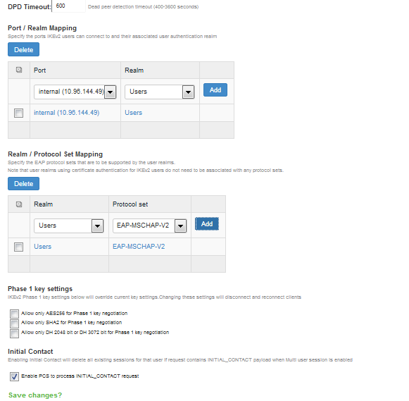
To enable IKEv2 User Access Logs:
1.Select System>Logging/Monitoring>User Access>Log Settings.
2.Under Select Events to Log, make sure to enable the Ivanti Secure Access Client Messages checkbox.
3.Click Save Changes.
IKEv2 Configuration Overview
IKEv2 EAP supports the following authentication server types:
•Local authentication
•Active Directory
•Certificate Server (applicable only for EAP-TLS)
If you are using IKEv2 EAP authentication on a local authentication server, you must select the Pass-word stored as clear text check box in the Auth Server page of the admin console. Note that you can-not edit an existing local authentication server instance to select this option. If you require IKEv2 EAP authentication on a local authentication server, you must create a new local authentication server in-stance.
IKEv2 EAP does not work with any preexisting local authentication servers since they do not store passwords in clear text.
To configure support for IKEv2:
- Configure your client for using IKE. For more information, see your mobile device's documentation.
- Install client and device certificates.
- You need a Certificate Authority (CA) that can issue client certificates.
- On the client side, install this client certificate along with the CA certificate.
- On the Ivanti Connect Secure server side, install the CA certificate under Configura-tion/Certificates/Trusted Client CAs.
- On the client side, install the Connect Secure certificate corresponding to the port to which the client connects, found under Configuration/Certificates/Device Certificates.
- Define an IKEv2 rule under the Users > User Realms > User > Role Mapping page of the admin console.
- Select the IKEv2 access feature under the Users > User Roles > User > General > Overview page of the admin console.
- Enable Network Connect for the Role and configure an NC Connection Profile (IP pool) to use for that Role.
When a client uses IKEv2 to connect to the host, the Agent Type column of the Active Users page dis-plays IKEv2.
Enabling the IKEv2 Phase-1 Key Settings
IKEv2 has a two-phase negotiation process. The first phase is known as IKE_SA_INIT and the second phase is known as IKE_AUTH. IKE_SA_INIT Phase exchanges the Security Association (SA) proposals, which comprises Encryption and Integrity algorithms, Diffie-Hellman Group, to derive Keys for IKE_AUTH Phase. These Security Association proposals preference can be controlled by different con-figurations in Ivanti Connect Secure.
To Configure Phase-1 Key Settings, select System > Configuration > IKEv2 > Phase 1 Key Settings. Three new UI options are available to enforce Encryption Algorithm (AES256), Integrity Algorithm (SHA256, SHA384 and SHA512) and Diffie-Hellman Group (DH 2048 and DH3072). Enabling these op-tions mean more secured Phase 2 negotiations. When AES256 is enabled, AES256 Encryption Algorithm is preferred over AES128 or 3DES. When SHA2 is Enabled, SHA2 Integrity Algorithm is preferred over SHA1 and When DH is Enabled, DH2048 or DH3072 Diffie-Hellman Group is preferred over DH1024. See figure below for Phase-1 Key Settings (In the main Menu bar: System):
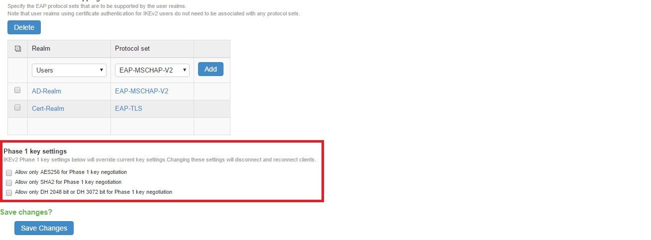
By default, these check boxes are disabled for backward compatibility. Enabling the check boxes will override current key settings and will disconnect connected clients if any.
Configuring IKEv2 Phase-2 Key Settings
The Phase-2 Key Exchange is also known as IKE_AUTH. The IKE_AUTH exchange is used to authenticate the remote endpoint and to securely establish IPSec Security association or Child SA. Only PSA platforms support SHA256. The following encryption and integrity combinations are sup-ported:
•AES128 + SHA1/MD5
•AES256 + SHA1/MD5/SHA256
•AES128 + SHA1/MD5
To configure IKEv2 Phase-2 parameters:
1.Select Resource Policies -> VPN Tunneling -> Connection Profile.
2.Under Encryption, select the suitable encryption and integrity combination.
The image below, indicates the options available for encryption: 
Enabling the IKEv2 Initial Contact
When an endpoint either crashes or reinitializes its state, the other endpoint should detect those con-ditions and stop sending any data. The INITIAL_CONTACT notification asserts that IKE Security Associa-tion (SA) is the only IKE SA currently active between the authenticated identities. It may be sent when an IKE SA is established after a crash, and the recipient may use this information to delete any other IKE SAs it has to the same authenticated identity without waiting for a timeout.
Enabling Initial Contact deletes all existing sessions for that user if request contains INITIAL_CONTACT payload when Multi user session is enabled.
When multiuser session is disabled, the server will always delete the existing session for that user before creating a new session.
To configure IKEv2 Initial Contact:
1.Select System > Configuration > IKEv2.
2.In the Initial Contact section, select the Enable Ivanti Connect Secure to process INITIAL_CONTACT request check box.
Enabling the IKEv2 Access Feature
Roles specify the session properties, including enabled access features, for users who are mapped to the role.
To enable the IKEv2 access feature:
1.Select User > User Roles > Role Name > General > Overview.
2.Under Access Features, check the VPN Tunneling check box.
3.Click Save Changes.
Enabling the IKEv2 EAP TLS User Access Logs
1.Select System>Logging/Monitoring>User Access>Log Settings.
2.Under Select Events to Log, make sure to enable the Ivanti Secure Access Client Messages check box.
3.Click Save Changes.
Defining the IKEv2 Role Mapping Rule
Role mapping rules are conditions a user must meet for the system to map the user to one or more user roles.
The procedure described in this topic is required only if you want to create a separate role mapping rule specific for IKEv2 users. If you use regular username, group or custom expression-based role mapping rules (typically used for general access to a device), the following procedure is not required.
1.Select User > User Realms > User > Role Mapping.
2.Click New Rule.
3.Select Custom Expressions as the type of condition on which to base the rule.
4.Click Update to display the Expressions list.
5.Click the Expressions button to display the Expressions tab of the server catalog.
6.Create a rule: userAgent = "IKEv2".
7.Click Add Expression and then Close.
8.Select the rule you just created from the Available Expressions list and click Add to move it to the Se-lected Expressions list.
9.Specify the roles to assign to the authenticated user by adding roles to the Selected Roles list.
10.(optional) Check the Stop processing rules when this rule matches check box if you want the system to stop evaluating role mapping rules when the user meets the conditions specified for this role.
11.Click Save Changes.
Using the Mobile Options
This topic describes the mobile options that are available on Ivanti Connect Secure. To configure the mobile option, go to System > Configuration > Mobile. It includes the following information:
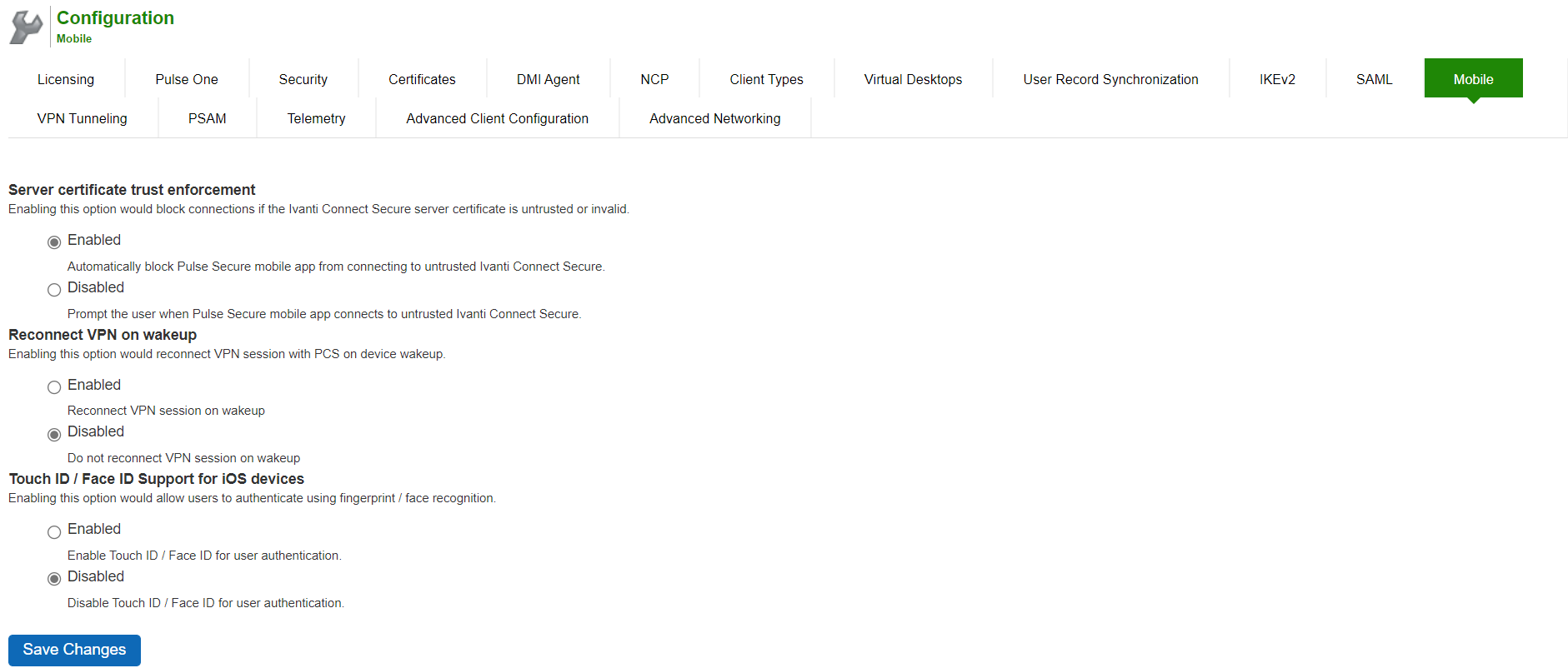
The following table lists the Configuring the Mobile Options:
|
Option |
Description |
|
Server certificate trust enforcement |
Enables you to block connections if the Ivanti Connect Secure server cer-tificate is untrusted or invalid. When enabled, it automatically blocks the mobile app from connecting to untrusted Ivanti Connect Secure. When disabled, it prompts when a mobile app connects to untrusted Ivanti Connect Secure. |
|
Reconnect VPN on wakeup |
Enables you to reconnect a VPN session with Ivanti Connect Secure on device wakeup. |
|
Touch ID / Face ID Sup-port for iOS devices |
Enables you to authenticate using fingerprint / face recognition. |
Using the Advanced Client Configuration Feature
This topic describes the XML advanced client configuration that can be used by the Ivanti Connect Secure administrator to configure the custom settings, which are meant to solve a specific customer scenario without changing the Ivanti Connect Secure admin console. Admin can set these custom settings in the form of XML input through the Advanced Client Configuration UI feature. Ivanti Secure Access Client supporting these custom settings will consume them when connecting to this Ivanti Connect Secure, and the same would be applied on the client ma-chines. From 9.0R3 release onwards, this feature will minimize the number of changes going into the Ivanti Connect Secure admin console, in order to fulfill a custom requirement of a specific customer.
Basically, the formula used to calculate the virtual adapter MTU is:
MIN (Physical Adapter MTU, MTU from Ivanti Connect Secure, TCP MSS value + 40)
Following is one of the scenarios where Firewall on the data path is stripping the TCP MSS options be-ing advertised by Ivanti Connect Secure to the Ivanti Secure Access Client. In this scenario, the TCP MSS value on the Ivanti Secure Access Client will default to a minimum value of 536, and as a result the client side MTU calculation will result in a mini-mum MTU value of 576. Here, customer wants to ignore the TCP MSS options while calculating the Vir-tual Adapter MTU calculation.
If the administrator configures the Ivanti Connect Secure sever with the following XML input in "Advanced Client Configuration for Ivanti Secure Access Client" option, it will ignore TCP MSS options while calculating the virtual adapter MTU on client side.
1.Select System > Configuration > Advanced Client Configuration to display the configuration page. Figure shows the configuration page for Ivanti Connect Secure.
2.Enter the following XML input in "Advanced Configuration for Ivanti Secure Access Client".
<advanced-config>
<version>9.0.3</version>
<desktop-client-config>
<layer3-connection-config>
<adapter-config>
<ignore-tcp-mss>TRUE</ignore-tcp-mss>
</adapter-config>
</layer3-connection-config>
</desktop-client-config>
</advanced-config>
3.Click Save Changes.
The advanced configuration setting "ignore-tcp-mss" is Layer3 Adapter configuration setting and this will be consumed by the Ivanti Secure Access Client as part of the IpsecConfig.
This "ignore-tcp-mss" setting is applicable for the virtual adapter MTU calculation only for IPv4. By default, the setting is always false, and therefore the TCP MSS options are always consid-ered for MTU by default. Admin has to explicitly set the ignore-tcp-mss setting to TRUE (case-insensitive), to ignore TCP MSS.
Using the Traffic Segregation Feature
This topic describes the traffic segregation feature that is available on the Connect Secure virtual appli-ance (service provider edition).
Traffic Segregation Feature Overview
Service providers often need a way to cleanly segregate the system-generated network traffic across interfaces (such as Internal, Management and VLAN ports), to differentiate AAA traffic from others.
Traffic segregation is supported for the following Scenarios:Radius
Certificate Auth including ANY CRL/OCSP verification.
•SAML
•AAA DNS Traffic
•DMI
•System logging (syslog)
•AD- Domain Join
•AD- Server Catalog
•AD-User Auth
•AD-Authrz
•AD-PMI
•LDAP-Test Connection
•LDAP-User Auth
•LDAP-User Auth- Referal user
•LDAP-SearchCatalog
•LDAP-Grplookup-UserLogin
•LDAP-PMI
Unsupported features include the following:
•Ace Auth
- For 9.0R2 and previous releases, enable the Send AAA Traffic via Management Port to send AAA traffic through management port. From 9.0R3 release, this option is enhanced and modified. For more information see, AAA Traffic Management.
- DMI/Netconf listens only on the default internal IP and default management IP. VIP IP addresses must not be used for DMI communication with Ivanti Connect Secure.
Two typical service provider deployment models are:
•Authentication server of the customer is hosted by the customer
•Authentication server for the customer is hosted and managed by the service provider
In both models, the service provider's authentication server is always hosted in the service provider's network and is reachable either through the internal or management port. In the first model, the cus-tomer's authentication servers are reachable through the internal port of the virtual appliance. In the second model, the customer's authentication server must be routed either through the internal or management port, depending on where the service provider has hosted the customer's authentica-tion server.
A Traffic Segregation menu is available only on virtual appliances to allow system providers to config-ure the interface and traffic. The "Default Network" is used as the primary logical network for the ser-vice provider and customer configuration. If traffic segregation across different logical networks is needed, the "Administrative Network" can be used.
You can differentiate AAA traffic from other traffic and route it through the management port. This is useful when the only the authentication servers are hosted on the network reachable through the management port and all other resources uses a different port. This option is available on both the Default Network and the Administrative Network.
The configurations to do on the virtual appliance depend on the logical network setup around the vir-tual appliance and the type of service provider deployment model:
•If both the service provider's and customer's authentication server are reachable through the same interface, the entire configuration for the service provider and customer is done under the De-fault Network. It is not necessary to enable the Administrative Network.
•If the service provider's and customer's authentication servers are located on two different networks, the Administrative Network must be created. The following table shows where the administrator configures the options in the system GUI.
The following table describes the Configuring Traffic Segregation Options:
|
Options |
Description |
|
Network Set-tings and Tools |
Enables you to change standard network settings; print a routing table; print or clear an ARP cache; run the ping and traceroute commands, remove static routes, add an ARP entry, view cluster status, configure management port, and change traffic control settings (Note: For change traffic control settings, the goal of the change is to change the priority of traffic in IVE de-pending on its criticality). |
|
Create admin username and password |
Enables you to create a new super administrator account. |
|
Display log |
Enables you to display system configuration, user access logs, or administra-tor access logs through the serial console. Note that must enter q to return to serial console options after viewing the logs. |
|
System Oper-ations |
Enables you to reboot, shut down, restart, roll back, or factory reset the system without using the admin console. |
|
Toggle pass-word protection for the console |
Enables you to password protect the serial console. When you toggle this option to "on," only super administrators are allowed access. |
|
Create a Super Admin session |
Enables you to create a recovery session to the admin console, even if you have configured the system to block access to all administrators. When you select this option, the system generates a temporary token that is valid for 3 minutes. Enter the following URL into a browser window: Then, enter the temporary token when prompted to sign in to the admin console. When you select this option, the system blocks any additional administra-tors from signing in to the admin console until you sign in to the specified URL and initiate a session using your token. The appliance blocks additional sign-in attempts so that you can fix any configuration problems that the sys-tem may have encountered without conflicting with another session. |
|
System Snap-shot |
Enables you to take a system snapshot without using the admin console. When you select this option, the system takes the snapshot immediately. You can then send the snapshot file, by way of SCP, to a remote system. The system prompts you for the destination server port, user ID, password, and the destination path to the remote directory. If you choose not to send the snapshot file to a remote system, the system saves the file locally. The next time you log in to the admin console, the Sys-tem Snapshot tab contains a link to the snapshot file. |
Using the Serial Port
This topic describes use of the serial port and serial port console.
Connecting to the Serial Port Console
In cases where the admin console is unavailable, you can perform network and host configuration tasks and troubleshooting using the serial port console.
To connect to the serial console:
1.Plug a null modem crossover cable from a console terminal or laptop into the device serial port. This cable is provided in the product box. Do not use a straight serial cable.
2.Configure a terminal emulation utility, such as HyperTerminal, with the following serial connection pa-rameters:
•9600 bits per second
•8-bit No Parity (8N1)
•1 Stop Bit
•No flow control
3.Press Enter until the serial console is displayed.
The following figure depicts the Serial Console Menu Options:
The following table lists the Serial Console Menu:
|
Options |
Description |
|
Network Set-tings and Tools |
Enables you to change standard network settings; print a routing table; print or clear an ARP cache; run the ping and traceroute commands, remove static routes, add an ARP entry, view cluster status, configure management port, and change traffic control settings (Note: For change traffic control settings, the goal of the change is to change the priority of traffic in IVE de-pending on its criticality). |
|
Create admin username and password |
Enables you to create a new super administrator account. |
|
Display log |
Enables you to display system configuration, user access logs, or administra-tor access logs through the serial console. Note that must enter q to return to serial console options after viewing the logs. |
|
System Oper-ations |
Enables you to reboot, shut down, restart, roll back, or factory reset the system without using the admin console. |
|
Toggle pass-word protection for the console |
Enables you to password protect the serial console. When you toggle this option to "on," only super administrators are allowed access. |
|
Create a Super Admin session |
Enables you to create a recovery session to the admin console, even if you have configured the system to block access to all administrators. When you select this option, the system generates a temporary token that is valid for 3 minutes. Enter the following URL into a browser window: Then, enter the temporary token when prompted to sign in to the admin console. When you select this option, the system blocks any additional administra-tors from signing in to the admin console until you sign in to the specified URL and initiate a session using your token. The appliance blocks additional sign-in attempts so that you can fix any configuration problems that the sys-tem may have encountered without conflicting with another session. |
|
System Snap-shot |
Enables you to take a system snapshot without using the admin console. When you select this option, the system takes the snapshot immediately. You can then send the snapshot file, by way of SCP, to a remote system. The system prompts you for the destination server port, user ID, password, and the destination path to the remote directory. If you choose not to send the snapshot file to a remote system, the system saves the file locally. The next time you log in to the admin console, the Sys-tem Snapshot tab contains a link to the snapshot file. |
Using the Serial Console to Roll Back to a Previous OS Version
You can use the admin console to roll back the configuration to a previous state. If the rollback option is not available in the admin console, you can use the procedure described in this section to perform the system rollback.
If you have not yet performed an OS service package upgrade, there is no previous state to roll back to, and the rollback option is not available. If you have performed an OS service package upgrade, any system and user configuration data created after the upgrade is lost unless you export the most cur-rent configuration files before rolling back the system and then import them afterwards.
To roll back to the previous OS service package:
1.Connect to the serial console.
2.In a browser window, sign in to the admin console.
3.Select Maintenance > System > Platform.
4.Click Reboot Now and then return to the console utility window. The window displays a message that the system is restarting.
5.After several moments, you are prompted to use the Tab key to select options. Press Tab, and when prompted for the configuration to load, type rollback and then press Enter.
After you click Reboot Now, the rollback status is output to the screen, and when complete, you are prompted to press Return (Enter) to modify system settings, which returns you to the initial setup op-tions. When you are finished entering data, simply close the serial console window.
If you wait more than 5 seconds to enter your choice, the current system configuration is automatically loaded, and you must go back to the admin console and click Reboot Now to start the process again. If you have already performed a system rollback, the rollback option is not available again until you up-grade the OS service package again.
Using the Serial Console to Reset the System to the Factory Image
In rare cases, you might need to reset the system to its original factory settings. Before performing this advanced system recovery option, contact our representative using Support Site. If possible, export the most current system and user con-figuration data before performing a factory reset.
To perform a factory reset:
1.Connect to the serial console.
2.In a browser window, sign in to the admin console.
3.Select Maintenance > System > Platform.
4.Click Reboot and then go back to the console utility window. The window displays a message that the system is restarting.
5.After several moments, you are prompted to use the Tab key to select options. Press Tab, and when prompted for the configuration to load, type factory-reset and then press Enter.
If you wait more than 5 seconds to enter your choice, the current system configuration is automatically loaded, and you must go back to the admin console and click Reboot Now to start the process again.
6.When you are prompted to confirm performing a factory reset, type proceed and then press Enter.
The system begins the process of resetting the machine to its original settings and outputs several screens of data. After several minutes, you are prompted to use the Tab key to select configuration choices.
7.When prompted to press the Tab key, do one of the following:
1. Wait for the default selection (current) to start automatically.
2. Press Tab, type current, and then press Enter.
You are then prompted to enter the initial configuration settings. For details on how to proceed, see the Installation Guide provided in the product packaging or on the Ivanti Support site.
After you complete the initialization process, you can upgrade to the latest OS service package and import saved system and user configuration files to return to the last good working state of your sys-tem.
You might receive errors from the system during the initial setup or on a factory reset. Before the sys-tem starts services, it monitors the network port for a maximum of 120 seconds. The system checks the link status and sends ARP requests to the default gateway. If there is a problem, after 5 seconds, the system displays a message on the serial console that starts with NIC:...... If the link recovers within 120 seconds, the startup process continues. If the link does not recover, the following message is dis-played:
Internal NIC: ................[Down code=0x1]
Two codes can appear:
•0x1 means that the interface link status reported by the NIC remains off (for example, a disconnected cable or a cable is in the wrong port).
•0x2 means that the gateway is unreachable. The system boots but is not reachable from IP addresses bound to that network port.