Configuring Gateways
Introduction
Note
This guide describes how to configure a ZTA Gateway for your secure applications and resources. To learn more about configuring Ivanti Connect Secure (ICS) Gateways, refer instead to the ICS Tenant Admin Guide available from the nZTA documentation portal.
A Gateway is a virtual machine instance that you use to control access to your applications. You deploy Gateway instances at each location your applications reside - at a physical datacenter, a private or public cloud-based service, or some hybrid combination. Each Gateway communicates with the Controller to ensure that application access requests received from end-user devices are authenticated.
Before you deploy a Gateway instance, you register a new Gateway record in the Controller through the Tenant Admin portal. This record contains all basic identification, type, and network details required to enable secure communication between the Controller and the Gateway instance. The registration process produces a package of settings, known as a Gateway definition, that you publish to the Gateway virtual machine instance during deployment. These settings enable the Gateway to establish communication back to the Controller.
Note
Make sure the Gateway virtual machine instance does not exist prior to registration with the Controller. Each ZTA Gateway must be deployed from the Controller directly. The Gateway definition file is designed to be published to a new virtual machine Gateway instance during its initial deployment.
You deploy a Gateway virtual machine instance from a supplied template. Each Gateway template is pre-configured to define the required virtual machine settings and network interfaces for the target platform. During deployment, you specify the values for each defined interface according to the public and private subnets configured in your network infrastructure.
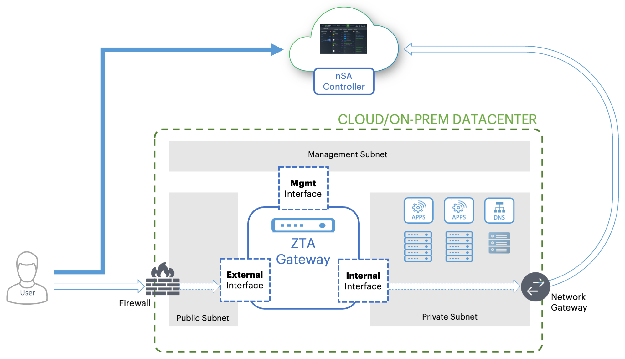
FIGURE 39 Gateway network connections in your cloud and on-prem datacenter
Each ZTA Gateway virtual machine uses a number of network interfaces:
External network interface: Configured with a public subnet IP address and used for external client access to the applications deployed in that datacenter. Use this IP address during the process of creating your Gateway record on the Controller.
Internal network interface: Configured with a private subnet IP address and used for internal connections to the deployed applications, and for external communication with the Controller.
(Optional) Management network interface: Configured with an IP address and port on a further, separate, network subnet for deployments where a specific management interface is required.
Note
When the management interface is enabled, the Gateway communicates with the Controller through this interface instead. In this scenario, the Gateway still uses the internal network interface for DNS resolution and NTP server communication. As such, the Gateway DNS server should resolve the Controller and NTP server FQDNs through the internal interface (internet access is required).
To ensure communication between your Gateways, the Controller, and your client users, make sure the following network connections are enabled:
Configure the firewall rules for the Public Subnet in which your ZTA Gateway External Interface resides is configured to accept inbound client connections on TCP port 443.
Configure the Network Gateway serving your Private Subnet to allow outbound TCP traffic to the Controller on port 443.
Configure the Network Gateway serving your Private Subnet to allow outbound UDP traffic to the following Network Time Protocol (NTP) services:
time.windows.com (port 123)
time.nist.gov (port 123)
If you are planning to use your ZTA Gateway to serve SaaS (Software-as-a-Service) applications, configure the application to restrict inbound connections to your network gateway IP address. This ensures that your SaaS application can be reached only by clients connecting through the ZTA Gateway.
If you maintain your own DNS service at the datacenter, use these details during Gateway record creation on the Controller.
White-listing Required IP Addresses for your Services
The Controller service uses a series of IP addresses and ports to facilitate access to the admin and user web consoles, for user enrollment, and for connections to a ZTA Gateway. To ensure network access, make sure the following IP addresses and ports are white-listed (or added to the allowed list) in your network firewalls and routing infrastructure. Select the IP addresses and ports for your corresponding region only:
North America:
52.186.44.249 (port 443)
52.188.33.186 (port 443)
Europe:
51.138.111.17 (port 443)
20.50.150.82 (port 443)
APJ:
20.44.238.229 (port 443)
20.44.237.67 (port 443)
High Availability
nZTA allows you to deploy multiple Gateways at a single location to support high availability. This arrangement can be used to provide scaling, redundancy, and load distribution for your application delivery.
High availability is implemented in the Controller through Gateway Groups. You add individual Gateways to a group, and then associate the group with your Secure Access Policy.
To learn more about high availability and using Gateway Groups, see the Tenant Admin Guide.
Configuring a Default Gateway
nZTA directs requests from each application towards the Gateway defined in the secure access policy for the application.
A default ZTA Gateway can be defined. This Gateway handles all requests from application that are not referenced by any secure access policy. This enables packet analysis to be conducted on requests passing through the Gateway to assess the validity of the requests. Two default Gateway scenarios are supported:
Any single Gateway at v21.1 (or later) can be assigned to act as the default Gateway. This Gateway is exclusively used as the default Gateway.
Alternatively, any Gateway Group whose Gateways are all at v21.1 (or later) can be assigned to act as the default Gateway. In this scenario, the Gateways are used exclusively as the default Gateway. The Gateway Group is typically fronted by a load balancer to enable the required distribution of requests across the Gateways in the group.
To configure a default ZTA Gateway, you must edit and update the built-in Application discovery secure access policy.
The default Gateway (or Gateway Group) then handles all requests from applications on enrolled devices that are not referenced by any other secure access policy.
To learn more about using a default Gateway, see the Tenant Admin Guide.
Gateway Deployment Workflows
nZTA supports Gateway virtual machine instances deployed in the following environments:
VMware vSphere: see Workflow: Creating a Gateway in VMware vSphere.
Amazon Web Services (AWS): see Workflow: Creating a Gateway in Amazon Web Services.
Microsoft Azure: see Workflow: Creating a Gateway in Microsoft Azure.
KVM/OpenStack: see Workflow: Creating a Gateway in KVM/OpenStack.
Google Cloud Platform: see Workflow: Creating a Gateway in Google Cloud Platform.
Workflow: Creating a Gateway in VMware vSphere
This workflow leads you through the process for setting up a Gateway in VMware vSphere. It contains two main procedures, in sequence:
Creating the Gateway record in the Controller.
Creating the Gateway virtual machine instance in VMware vSphere.
After these steps have been completed successfully, the Controller and Gateway establish communication with each other.
Before you start, make sure you have the following information and files for the Gateway:
An identifying name for the Gateway
The public IP address for the Gateway. This is the IP address at which clients can externally reach the Gateway instance.
The Gateway geographic location
(Optional) The name of the Gateway Group to which you want to add this new Gateway record. To learn more about Gateway Groups, see the Tenant Admin Guide.
Additionally, if you want to manually specify Gateway network interface settings:
The internal/private subnet IP address, subnet mask, and network gateway IP address.
The primary (and optional secondary) DNS server IP address, and search domain.
The external interface IP address, subnet mask, and network gateway IP address
(Optional) The management interface IP address, subnet mask, and network gateway IP address.
The Gateway OVF template: https://pulsezta.blob.core.windows.net/gateway/ISA-V-VMWARE-ZTA-22.3R4-883.1.zip
Note
Download a copy of the OVF template archive file and unpack to a local workstation. Make sure the resulting file set is accessible from the vSphere Console.
Note
You can also choose to download this file from the Gateways Overview page of the Tenant Admin Portal. The opportunity to do this occurs later in this process.
Credentials for the vSphere Console.
Note
These credentials must include sufficient permissions to create a virtual machine from a template image.
To set up a ZTA Gateway in VMware vSphere, perform the following steps:
Log into the Tenant Admin Portal using the credentials provided in your welcome email. Two outcomes are possible:
On unconfigured nZTA systems, the Secure Access Setup (Onboarding) wizard appears. In this case, click Add Gateway.
On configured nZTA systems, the Network Overview page appears. In this case:
From the nZTA menu, click the Secure Access icon, then select Gateways > Gateway List.
The Gateways List page appears, showing the full list of Gateway Groups and standalone Gateways currently configured on the Controller.
To add a new Gateway, select Create from the top-right:
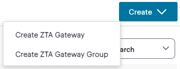
FIGURE 40 Add a new Gateway or Gateway Group
In the drop-down menu, click create ZTA Gateway.
In both cases, the Gateway Network Configuration dialog appears.
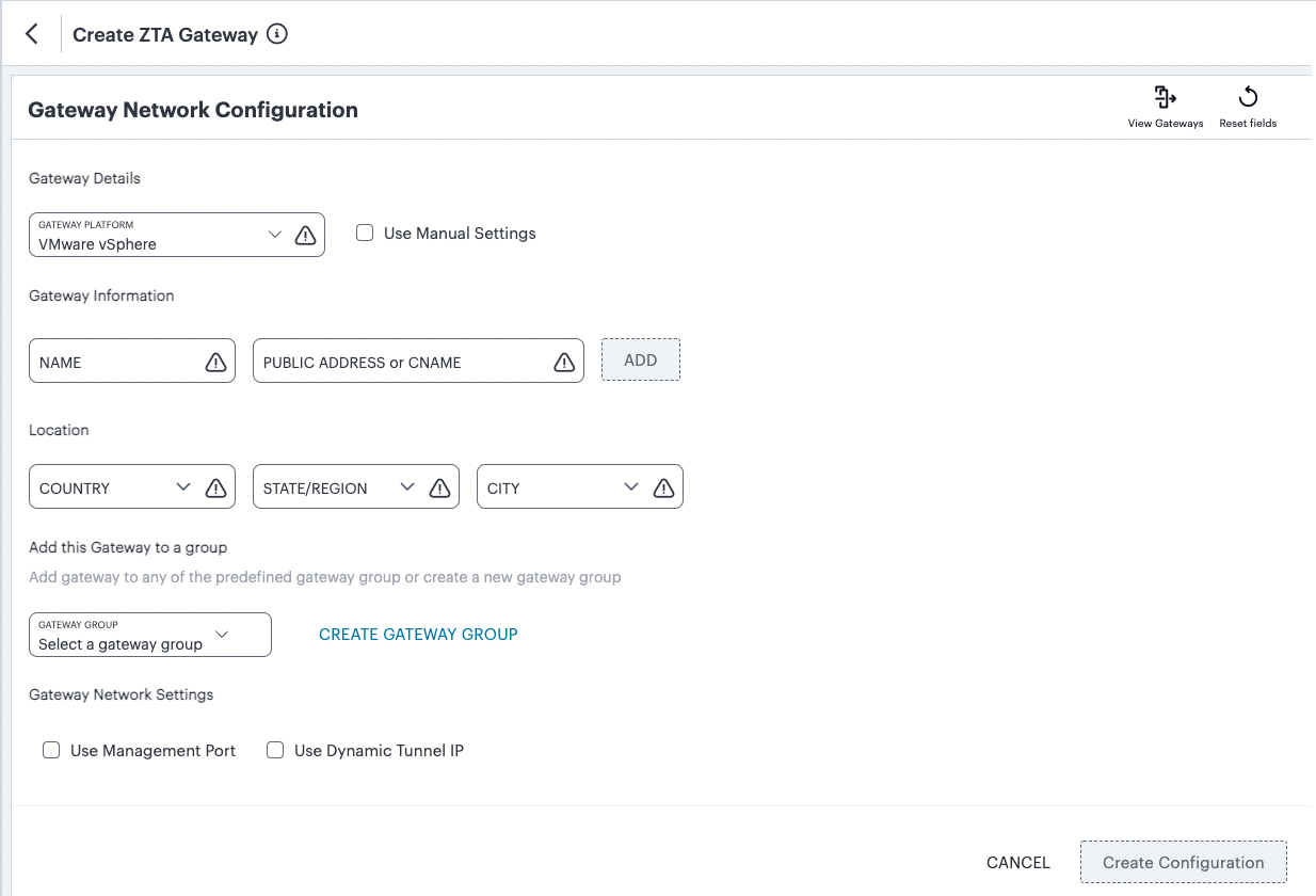
FIGURE 41 Gateway Network Configuration
Note
To learn more about the settings on this page, see the Tenant Admin Guide.
For Gateway Platform, select “VMware vSphere”.
(Optional) To enter your vSphere Gateway instance DNS and network interface settings manually, select Use Manual Settings. To instead allow nZTA to use DHCP-derived settings for DNS and network interfaces, leave Use Manual Settings un-selected.
Enter a Name for the Gateway.
Enter one or more Public Address or CNAME (Public IP address or CNAME) for the Gateway. Select Add to add each entry to the list.
Select a geographic Location for the Gateway.
(Optional) Select a Gateway Group to which the new Gateway is to be added.
(Optional) Select the Use Management Port check box to use management network ports for nZTA traffic rather than internal ports.
Note
When the management port is enabled, the Controller will still use the internal port for DNS resolution. If the internal DNS cannot resolve the Controller domain, the internal interface will require internet access.
(Optional) Select the Use Dynamic Tunnel IP check box to configure a pool of IP addresses that are dynamically mapped to client sessions with this Gateway, such that user traffic from the Gateway to an application can be identified as originating from a specific client.
The Custom IP Pool dialog appears:
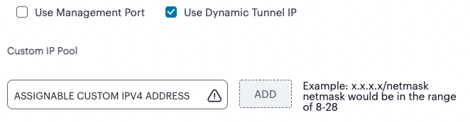
FIGURE 42 Gateway Network Configuration - Custom IP Pool settings
Note
Dynamic Tunnel IP addresses are not supported in Gateway Groups.
Use the Assignable Custom IPv4 Address field to enter an IP address and subnet (in the range 8-28) in CIDR notation, then click Add. Repeat this step for each address/subnet you want to use.
If you elected to use manual settings, the following panel appears:
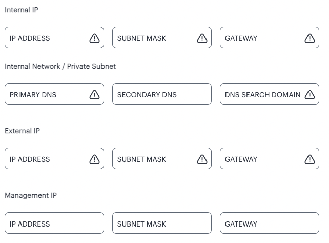
FIGURE 43 Gateway Network Configuration - manual settings
Enter the following details:
Specify the internal IP Address for the Gateway.
Specify the internal Subnet Mask for the Gateway.
Specify the internal network gateway IP address as the Gateway setting.
Enter the Primary DNS IP address for the Gateway.
(Optional) Enter the Secondary DNS IP address for the Gateway.
Enter the DNS Search Domain for the Gateway.
Specify the external IP Address for the Gateway.
Specify the external Subnet Mask for the Gateway.
Specify the external network gateway IP address as the Gateway setting.
Note
Management network settings are optional, unless the Use Management Port check box is selected.
Specify the management IP Address for the Gateway.
Specify the management Subnet Mask for the Gateway.
Specify the management network gateway IP address as the Gateway setting.
To add a Gateway definition based on the settings you specified in this dialog, select Create Configuration.
After you complete this process, an unregistered Gateway record is created on the Controller. You can view this Gateway record on the Gateways > Gateways List page.
On the Gateways List page, select your vSphere Gateway and click the Download icon to obtain a copy of the Gateway definition file.
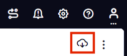
FIGURE 44 The Download Icon
Retain this file for a later step.
Note
The Gateway definition file is valid for 24 hours. If this period expires, you must replace the Gateway to generate a new Gateway definition file.
(Optional) If you have not yet downloaded the latest version of your Gateway VM file, click the Download icon and select Download gateway VM image. Save the archive file and unpack to a local workstation. Make sure the resulting file set is accessible from the vSphere Console.
Access the vSphere management interface, either from a client or a web browser, and log in using your vSphere credentials.
In the vSphere console, start the Deploy OVF Template wizard to create a new virtual machine based on the nZTA vSphere Gateway template.
In the wizard:
Choose to deploy from a local file.
Locate and upload your ZTA Gateway OVF/VMDK template files.
Provide an identifying name and location for the new Gateway virtual machine.
Choose any required compute resource.
Note
For reference, the recommended minimum requirements for a Gateway virtual machine instance in vSphere are:
4 vCPU’s and 8 GB memory, or
8 vCPU’s and 32 GB memory
Choose the required storage settings.
Customize the vApp properties of your virtual machine and, in the VA IVE Configuration parameter, paste the raw text of the Gateway definition file downloaded earlier.
Confirm all settings.
Finish the wizard to create the Gateway virtual machine.
Locate the new Gateway virtual machine in the hosts and clusters.
Start the Gateway virtual machine by powering it on.
Wait until the boot up process is complete.
Return to the Gateways List page on the Controller.
Locate the new Gateway record in the list and confirm that its Connection Status has updated to Connected.
Note
After you have registered a Gateway, you can configure it (or the Gateway Group to which it belongs) as the default Gateway if required. See the Tenant Admin Guide for details.
Workflow: Creating a Gateway in Amazon Web Services
This workflow leads you through the process for setting up a Gateway in Amazon Web Services (AWS). It contains two main procedures, in sequence:
Creating the Gateway record in the Controller.
Creating the Gateway virtual machine instance in AWS.
After these steps have been completed successfully, the Controller and Gateway establish communication with each other.
Before you start, make sure you have the following information and files:
An identifying name for the Gateway
The public IP address for the Gateway. This is the IP address at which clients can externally reach the Gateway instance, typically an elastic IP address provided by AWS.
The Gateway geographic location.
(Optional) The name of the Gateway Group to which you want to add this new Gateway record. To learn more about Gateway Groups, see the Tenant Admin Guide.
The primary (and optional secondary) DNS server IP address, and search domain.
The Gateway template file. A ZTA Gateway can be deployed in a new VPC or an existing VPC, using Nitro hypervisor. Select the JSON template file that is applicable to your requirements:
To deploy in an existing VPC - Nitro hypervisor (M5-type instances):
https://pulsezta.blob.core.windows.net/gateway/templates/AWS/23-2-883/Nitro/ivanti-zta-2-nics-existing-vpc.json
https://pulsezta.blob.core.windows.net/gateway/templates/AWS/23-2-883/Nitro/ivanti-zta-3-nics-existing-vpc.jsonTo deploy in a new VPC - Nitro hypervisor (M5-type instances):
https://pulsezta.blob.core.windows.net/gateway/templates/AWS/23-2-883/Nitro/ivanti-zta-2-nics-new-network.json
https://pulsezta.blob.core.windows.net/gateway/templates/AWS/23-2-883/Nitro/ivanti-zta-3-nics-new-network.json
Note
If you want to use a Management interface, you must download and use the 3 NIC template.
Note
You might not be able to specify the download location given here directly to AWS. In this case, download the Gateway template file first to your local workstation and specify this location instead.
Note
You can also choose to download this file from the Gateways Overview page of the Tenant Admin Portal. The opportunity to do this occurs later in this process.
The Gateway AMI identifier. nZTA gateway AMIs are available in all AWS regions (except China). To obtain the AMI applicable to your region, follow these steps:
Log into the AWS console.
Navigate to EC2 > Images > AMIs.
Select “Public Images”.
Search for the image corresponding to your selected hypervisor:
Nitro: “ISA-V-NITRO-ZTA-22.3R4-883.1-SERIAL-nitro.img”
Make a note of the corresponding AMI ID.
Credentials for the AWS Management Console.
Note
These credentials must include sufficient permissions to create a stack.
The SSH public key that you are using with the AWS Management Console.
To set up a ZTA Gateway in AWS, perform the following steps:
Log into the Tenant Admin Portal using the credentials provided in your welcome email. Two outcomes are possible:
On unconfigured nZTA systems, the Secure Access Setup (Onboarding) wizard appears. In this case, click Add Gateway.
On configured nZTA systems, the Network Overview page appears. In this case:
From the nZTA menu, click the Secure Access icon, then select Gateways > Gateway List.
The Gateways List page appears, showing the full list of Gateway Groups and standalone Gateways currently configured on the Controller.
To add a new Gateway, select Create from the top-right:
FIGURE 45 Add a new Gateway or Gateway Group
In the drop-down menu, click Create ZTA Gateway.
In both cases, the Gateway Network Configuration dialog appears.
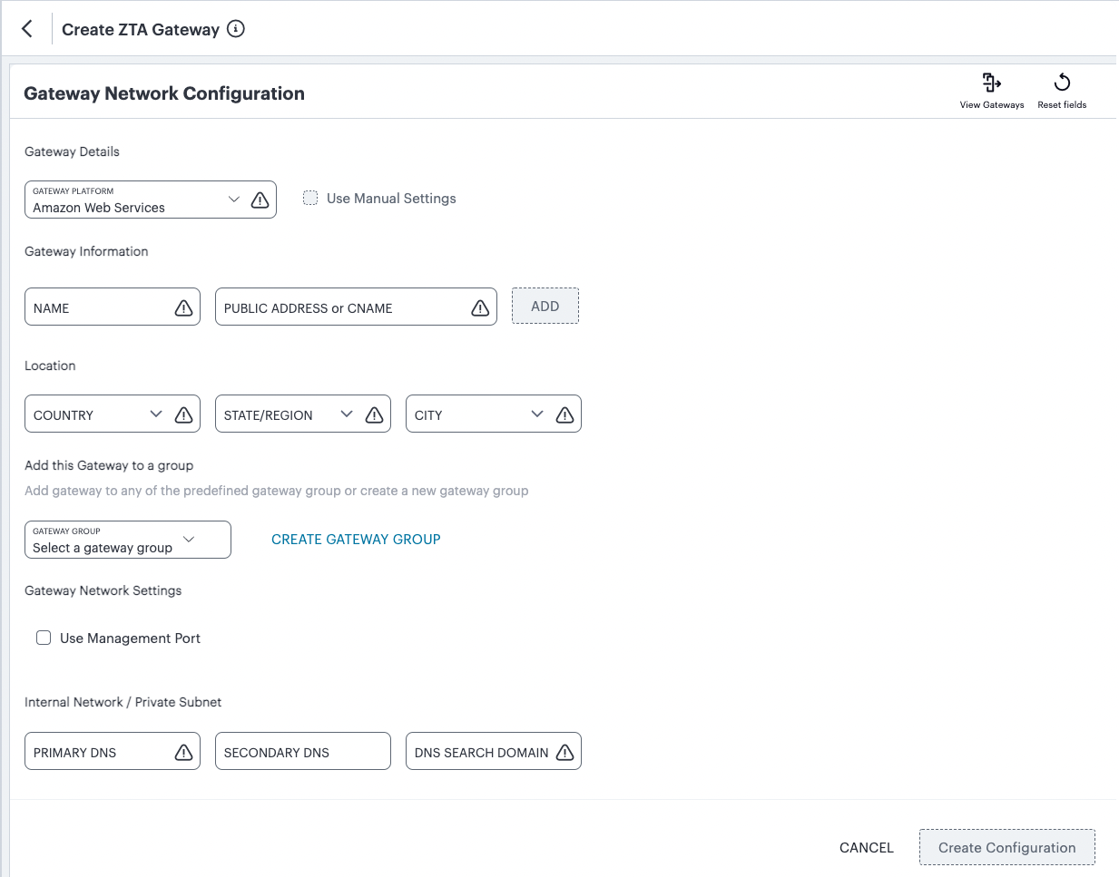
FIGURE 46 Gateway Network Configuration
Note
To learn more about the settings on this page, see the Tenant Admin Guide.
For Gateway Platform, select “Amazon Web Services”.
Enter a Name for the Gateway.
Enter one or more Public Address or CNAME (Public IP address or CNAME) for the Gateway. Select Add to add each entry to the list.
Select a geographic Location for the Gateway.
(Optional) Select a Gateway Group to which the new Gateway is to be added.
(Optional) Select the Use Management Port check box to use management network ports for nZTA traffic rather than internal ports.
Note
When the management port is enabled, the Controller will still use the internal port for DNS resolution. If the internal DNS cannot resolve the Controller domain, the internal interface will require internet access.
Enter the Primary DNS IP address for the Gateway.
(Optional) Enter the Secondary DNS IP address for the Gateway.
Enter the DNS Search Domain for the Gateway.
Note
Make sure the specified DNS service can resolve the IP address of your Controller. Issues here can cause registration of the Gateway with the Controller to fail.
To add a Gateway definition based on the settings you specified in this dialog, select Create Configuration.
After you complete this process, an unregistered Gateway record is created on the Controller. You can view this Gateway record on the Gateways > Gateways List page.
On the Gateways List page, select your new Gateway and click the Download icon to obtain a copy of the Gateway definition file.
FIGURE 47 The Download Icon
Retain this file for a later step.
Note
The Gateway definition file is valid for 24 hours. If this period expires, you must replace the Gateway to generate a new Gateway definition file.
(Optional) If you have not yet downloaded the latest version of your Gateway VM file, click the Download icon and select Download gateway VM image. Save the archive file and unpack to a local workstation. Make sure the resulting file set is accessible from the AWS Management Console.
Access the AWS Management Console and log in using your AWS credentials.
In the AWS Services menu, select CloudFormation.
The CloudFormation home page appears.
Click Create Stack and then, from the sub-menu, select With new resources (standard).
The Specify template step of the Create Stack wizard appears.
Under Prerequisite - prepare template, select the Template is ready option.
Under Specify Template, select the Upload a template file template source option.
Under Upload a template file, click Choose File and select the Gateway template file that you downloaded at the start of this process.
The file uploads, and the AWS S3 URL for the uploaded template file appears automatically.
Click Next.
The Specify stack details step of the Create Stack wizard appears. This page displays the details and parameters required by the Gateway template.
Enter a Stack name.
Specify the parameters as appropriate for your deployment:
If you are deploying the Gateway instance into a new VPC, you can accept the default values used for all parameters.
If you are deploying the instance into an existing VPC, you must manually specify the details of your existing VPC into the parameters on the page. For more information, contact Ivanti Technical Support.
Under nZTA Configuration, identify the required Gateway AMI using its nZTA Gateway AMI ID. Choose the designated AMI for the region in which you are deploying the Gateway instance.
For Instance Type, select the instance type that fits your hypervisor choice (Nitro) and minimum requirements, based on the following recommended types:
Note
For reference, the recommended minimum requirements for a Gateway virtual machine instance in AWS are:
For Nitro hypervisor-based instances, use M5 types:
m5.large (2 vCPU, 8 GB Memory) (2NIC min)
m5.xlarge (4 vCPU, 16 GB Memory) (3NIC min)
m5.2xlarge (8 vCPU, 32 GB Memory)
m5.4xlarge (16 vCPU, 64 GB Memory)
Under nZTA Config Data, paste in the raw text of the Gateway definition file downloaded earlier.
For SSH Key Name, specify your existing SSH key pair name.
For Load Balancer Configuration, If you plan to deploy multiple Gateways inside a Gateway Group, select “Yes” to deploy a new internet-facing network load balancer instance alongside the Gateway. Select “No” to launch only this Gateway instance.
Note
This option is applicable only for new VPC templates.
If you elect to launch a load balancer, the following pre-configuration is applied:
An Elastic IP address is assigned to the load balancer.
A TCP listener is configured on port 443.
An IP-based Target Group is created and the private IP address of the deployed Gateway’s external network interface is added as a target.
A health-check is configured on TCP port 443.
Stickiness is enabled on the Target Group.
After you have deployed the Gateway and Load Balancer, you must return to the Tenant Admin Portal on the Controller and update the Gateway Group Load Balancer IP ADDRESS setting to be the Load Balancer’s public IP address.
If you want to configure the Load Balancer to balance across further Gateway instances from the Gateway Group, you must deploy each subsequent Gateway into an existing VPC and then update the Load Balancer Target Group.
Note
With new VPC templates, a NAT gateway is deployed for routing outbound Internet traffic from the Gateway’s internal network interface in order for the Gateway to be able to reach the Controller.
Note
Public IP addresses are not automatically assigned to any of your Gateway’s network interfaces. If you are deploying a Gateway into an existing VPC, in order for the Gateway to be able to reach the Controller from it’s internal network interface, make sure you allow outbound Internet traffic from the Private Subnet for the deployed Gateway.
To learn more about high availability and Gateway Groups, see the Tenant Admin Guide.
Click Next.
The Configure stack options step of the Create Stack wizard appears. All properties that were specified either in the template or in earlier steps are populated automatically.
No changes or new inputs are required.
Click Next.
The Review step of the Create Stack wizard appears.
Confirm all displayed details.
Click Create stack.
The Stacks page appears. The new stack is listed using the Stack name you specified during the wizard. The new stack has a status of CREATE_IN_PROGRESS.
Wait for the status of the new stack to reach CREATE_COMPLETE.
(This step is required only if you have not deployed your Gateway with a Load Balancer or NAT at the front-end) Elastic IP addresses are not automatically assigned to any of the Gateway’s network interfaces. Therefore, before you can access the new Gateway instance from the Controller, you must associate a new Public IP address with the external interface of the Gateway. Then, return to the Tenant Admin Portal and update the Gateway Public IP Address setting to match this address.
In the Tenant Admin Portal Secure Access > Gateways > Gateways List page, locate the new Gateway record and confirm that its Connection Status has updated to Connected.
Note
You can directly access your AWS instance over SSH using AWS EC2 Instance Connect. To configure AWS EC2 Instance Connect, refer to the Amazon Web Service Documentation. You can then connect to the instance directly as a serial console using SSH from inside the AWS Management Console, refer to the Amazon Web Service Documentation.
Note
After you have registered a Gateway, you can configure it (or the Gateway Group to which it belongs) as the default Gateway if required. See the Tenant Admin Guide for details.
Workflow: Creating a Gateway in Microsoft Azure
This workflow leads you through the process for creating and registering a ZTA Gateway in Microsoft Azure. It contains two main procedures, to be completed in sequence:
Create the Gateway record in the Controller.
Create the Gateway virtual machine instance in Azure and register it with the Controller.
Azure offers two methods for launching a Gateway virtual machine instance:
Through the Azure Marketplace
Using the provided template and image files
Note
ZTA Gateway instances in Azure Marketplace is limited to version 21.3R1. To use a Gateway version later than 21.3R1, either launch the Azure Marketplace version and upgrade in-place to the latest version, or use the alternate procedure described below to launch a Gateway instance using the template and image files.
Before you start, make sure you have the following information and files:
An identifying name for the Gateway
The Gateway geographic location.
(Optional) The name of the Gateway Group to which you want to add this new Gateway record. To learn more about Gateway Groups, see the Tenant Admin Guide.
The primary (and optional secondary) DNS server IP address, and search domain.
The SSH public key that you are using with the Azure Portal or Management Console.
Note
SSH keys can be generated using sshkeygen on Linux and macOS, or PuTTyGen on Windows. For further details about generating SSH key pairs, see:
* For Windows: https://docs.microsoft.com/en-us/azure/virtual-machines/linux/ssh-from-windows
* For MacOS and Linux: https://docs.microsoft.com/en-us/azure/virtual-machines/linux/mac-create-ssh-keysCredentials for the Azure Portal or Management Console.
Note
These credentials must include sufficient permissions to create a virtual machine.
Additionally, if you are deploying a Gateway instance directly from the template and image files (as opposed to using the Azure Marketplace):
The Gateway template JSON file:
Note
A ZTA Gateway can be deployed in a new VNET or an existing VNET. Select the JSON template file applicable to your requirements.
To deploy in a new VNET:
https://pulsezta.blob.core.windows.net/gateway/templates/Azure/23-2-883/ivanti-zta-2-nics.json
https://pulsezta.blob.core.windows.net/gateway/templates/Azure/23-2-883/ivanti-zta-3-nics.jsonTo deploy in an existing VNET:
https://pulsezta.blob.core.windows.net/gateway/templates/Azure/23-2-883/ivanti-zta-2-nics-existing-vnet.json
https://pulsezta.blob.core.windows.net/gateway/templates/Azure/23-2-883/ivanti-zta-3-nics-existing-vnet.json
Note
If you want to use a Management interface, you must download and use the 3 NIC template.
A link to the Gateway template image file. Choose from:
Americas: https://pulsezta.blob.core.windows.net/gateway/ISA-V-HYPERV-ZTA-22.3R4-883.1-SERIAL-hyperv.vhd
APJ: https://pulseztaapj1.blob.core.windows.net/gateway/ISA-V-HYPERV-ZTA-22.3R4-883.1-SERIAL-hyperv.vhd
Europe: https://pulseztaeurope.blob.core.windows.net/gateway/ISA-V-HYPERV-ZTA-22.3R4-883.1-SERIAL-hyperv.vhd
Use the link most suitable for your geographic location. The instructions that follow include details of how to use azcopy to copy the VHD file into your storage account.
Note
You can also choose to download this file from the Gateways Overview page of the Tenant Admin Portal. The opportunity to do this occurs later in this process.
A public IP address or CNAME for the Gateway. This is the IP address or CNAME at which client devices can externally reach the Gateway instance.
To create a Gateway record in the Controller, perform the following steps:
Log into the Tenant Admin Portal using the credentials provided in your welcome email. Two outcomes are possible:
On unconfigured nZTA systems, the Secure Access Setup (Onboarding) wizard appears. In this case, click Add Gateway.
On configured nZTA systems, the Network Overview page appears. In this case:
From the nZTA menu, click the Secure Access icon, then select Gateways > Gateway List.
The Gateways List page appears, showing the full list of Gateway Groups and standalone Gateways currently configured on the Controller.
To add a new Gateway, select Create from the top-right:
FIGURE 48 Add a new Gateway or Gateway Group
In the drop-down menu, click Create ZTA Gateway.
In both cases, the Gateway Network Configuration dialog appears.
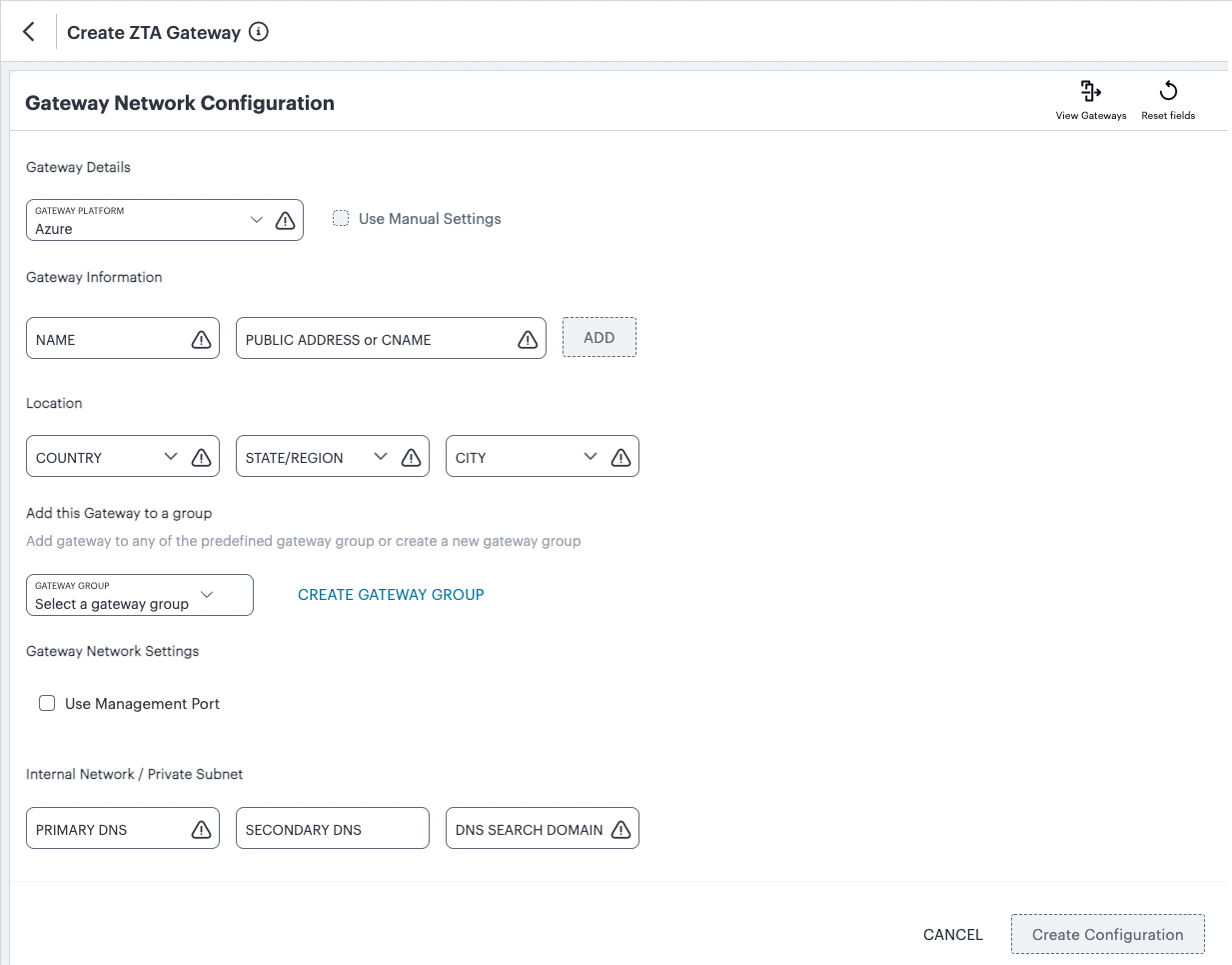
FIGURE 49 Gateway Network Configuration
Note
To learn more about the settings on this page, see the Tenant Admin Guide.
For Gateway Platform, select “Azure”.
Enter a Name for the Gateway.
Enter one or more Public Address or CNAME (Public IP address or CNAME) for the Gateway. Select Add to add each entry to the list.
Note
For Azure Marketplace deployments, a public IP address or CNAME is typically allocated at deployment time through the Azure Portal. Therefore, if you do not yet know the expected address/CNAME, enter a dummy value in this field now and update the setting after you have deployed and registered the Gateway instance. For more details on this process, see Creating a Gateway through Azure Marketplace.
Select a geographic Location for the Gateway.
(Optional) Select a Gateway Group to which the new Gateway is to be added.
(Optional) Select the Use Management Port check box to use management network ports for nZTA traffic rather than internal ports.
Note
When the management port is enabled, the Controller will still use the internal port for DNS resolution. If the internal DNS cannot resolve the Controller domain, the internal interface will require internet access.
Enter the Primary DNS IP address for the Gateway.
(Optional) Enter the Secondary DNS IP address for the Gateway.
Enter the DNS Search Domain for the Gateway.
Note
Make sure the specified DNS service can resolve the IP address of your Controller. Issues here can cause registration of the Gateway with the Controller to fail.
To add a Gateway definition based on the settings you specified in this dialog, select Create Configuration.
After you complete the first part of this workflow, an unregistered Gateway record is created on the Controller. This Gateway record can be seen on the Gateways > Gateways List page.
On the Gateways List page, select your new Gateway and click the Download icon to obtain a copy of the Gateway definition file.
FIGURE 50 The Download Icon
Retain this file for a later step.
Note
The Gateway definition file is valid for 24 hours. If this period expires, you must replace the Gateway to generate a new Gateway definition file.
(Optional) If you have not yet downloaded the latest version of your Gateway VM file, click the Download icon and select Download gateway VM image. Save the archive file and unpack to a local workstation. Make sure the resulting file set is accessible from the Microsoft Azure Console.
Next, decide which Azure deployment process you want to follow - launching an instance through Azure Marketplace, or creating an instance using the supplied template and image files.
To launch an instance from Azure Marketplace, see Creating a Gateway through Azure Marketplace.
To create an instance using the nZTA template and image files, see Creating an Gateway using the Azure Template and Image Files.
Creating a Gateway through Azure Marketplace
Note
ZTA Gateway instances in Azure Marketplace are limited to version 21.3R1 at the present time. To use a Gateway version later than 21.3R1, either launch the Azure Marketplace version and upgrade in-place to the latest version (for more details, see the Tenant Admin Guide) or use the alternate procedure described in Creating an Gateway using the Azure Template and Image Files to launch a Gateway instance using the template and image files.
To launch a Gateway virtual machine in Microsoft Azure from the Azure Marketplace, perform the following steps:
Log into the Microsoft Azure Portal (http://portal.azure.com).
Navigate to the Azure Marketplace by clicking Create a resource.
In the Search the Marketplace text box, enter “Ivanti”.
Azure Marketplace presents the results relevant to your search term.
Locate Ivanti Neurons Zero Trust Access Gateway and click Create.
In the drop-down list, choose the option that is applicable to your needs:
Ivanti Neurons Zero Trust Access Gateway - BYOL 3 NIC: Includes 3 network interfaces (internal, external, and management)
Ivanti Neurons Zero Trust Access Gateway - BYOL 2 NIC: Includes 2 network interfaces (internal and external)
Note
To first learn more about Ivanti Neurons Zero Trust Access Gateway, click the product banner and view the associated information page. You can launch a new Gateway instance from this page.
The Create Ivanti Neurons Zero Trust Access Gateway process appears.
On the Basics tab, enter the following details:
Subscription: If you are using the “PZT_Dev” subscription, leave this field as the default value. Otherwise, enter your subscription name.
Resource Group: Specify the resource group in which the Gateway needs to be deployed, or create a new resource group using the link provided. An Azure Resource Group is a container for a collection of connected assets that you assign to a virtual machine. To learn more, see the Azure documentation (https://docs.microsoft.com/azure).
Region: Specify the geographic region in which the Gateway instance is deployed.
Ivanti Neurons Zero Trust Access Gateway VM Name: Enter a suitable name for your Gateway instance. This name must be 1-9 characters long, using only lowercase letters or numbers.
SSH Public Key Source: Select “Use existing public key”.
SSH Public Key: Copy and paste an RSA public key in a single-line format or the multi-line PEM format.
Note
SSH keys can be generated using sshkeygen on Linux and macOS, or PuTTyGen on Windows. For further details about generating SSH key pairs, see:
* For Windows: https://docs.microsoft.com/en-us/azure/virtual-machines/linux/ssh-from-windows
* For MacOS and Linux: https://docs.microsoft.com/en-us/azure/virtual-machines/linux/mac-create-ssh-keysTo continue, click Next: Network Settings >.
On the Network Settings page, enter the following details:
Virtual Network: A virtual network is a logical isolation of the Azure cloud dedicated to your services. The value you enter here affects the IP address and subnet allocations for all network interfaces shown on this page. Azure pre-populates this field with a new virtual network name, although you can select your own predefined virtual network as necessary.
To create a new virtual network, perform the following steps:
Click the Create New link under the Virtual Network setting.
The Create virtual network dialog appears.
Enter a virtual network name.
Enter an address space in CIDR notation (for example, 192.0.2.0/24).
For each interface subnet, use the automatically-populated name and address values provided, or enter your own details. Each subnet must be contained by the address space entered in the previous setting.
To save your changes, click OK.
Your new virtual network settings are populated into the corresponding interface settings in the main Network Settings page.
Internal Subnet: The subnet identifier for the Internal network, pre-populated by either the selected Virtual Network or your newly-entered virtual network settings.
External Subnet: The subnet identifier for the External network, pre-populated by either the selected Virtual Network or your newly-entered virtual network settings.
(For 3 NIC instances only) Management Subnet: The subnet for the Management network, pre-populated by either the selected Virtual Network or your newly-entered virtual network settings.
Public IP for Ivanti Neurons Zero Trust Access Gateway external interface LB: The public IP address identifier at which clients can externally reach the Gateway instance, typically provided by Azure.
Note
Before you can connect to the new Gateway instance from the Controller, you must update the Controller with the Public IP address or CNAME assigned to the external interface of the Gateway load balancer. This process is described later.
DNS prefix for external interface LB: The unique DNS name for the public IP address specified for the external interface load balancer.
Public IP for NAT Gateway: The public IP address identifier of a NAT Gateway for the virtual machine to communicate with the Controller and other public resources.
DNS prefix for NAT Gateway public IP: The unique DNS name for the public IP address specified for the internal interface NAT Gateway.
Deploy Ivanti Neurons Zero Trust Access Gateway with Load Balancer: To deploy this Gateway with a load balancer, select “Yes” from the drop-down list. The front-end IP address of the load balancer is then used as the public IP address for your Gateway.
Note
If you select “No” to not deploy a load balancer, you must create and associate a public IP address to the external interface of your instance after deployment is complete.
In all cases, on completion of this process, you must update the Controller Gateway definition with the correct public IP address for your Azure Gateway instance.
To continue, click Next: Instance Configuration >.
On the Instance Configuration page, enter the following details:
Ivanti Neurons Zero Trust Access Gateway VM Size: This is the specification of the virtual machine. Choose from:
For 2nic instances, select “1 x Standard DS2 v2”
For 3nic instances, select “1 x Standard DS4 v2”
Diagnostic storage account: The storage account for the virtual machine diagnostics. The default value is a new account based on your VM name.
Ivanti Neurons Zero Trust Access Gateway Version: Specify the version applicable to the current nSA version, or the version you require. Ivanti recommends you select the latest available version.
Ivanti Neurons Zero Trust Access Gateway Config Data: Paste in the raw text of your Gateway definition file. To obtain the Gateway definition file, see the process described earlier in this section.
To continue, click Next: Review + create >.
On the Review + create page, verify the proposed configuration is validated successfully, and then click Create to create your new Gateway instance.
After a short wait, your instance is created and deployed.
Access the virtual machine settings for your new Gateway instance, and click Networking from the Settings menu.
The Networking dialog appears, showing your attached network interfaces (internal, external, and (optionally) management).
Click the tab that corresponds to the external network interface.
The settings for the external network interface appear.
Locate the NIC Public IP field and make a note of the IP address shown there. This is the public IP address you use to reconfigure the Controller record for this Gateway.
If no public IP address is shown, determine if a load balancer was deployed together with your Gateway instance by selecting the Load balancing tab.
If a load balancer was deployed, make a note of the Frontend IP address displayed in this tab and use this as the Gateway public IP address on the Controller.
If a load balancer was not deployed, create a public IP address and associate it with the external interface. Then, use this IP address as the Gateway public IP address on the Controller.
Note
To learn about configuring IP addresses in the Azure portal, see the Microsoft Azure documentation.
Return to the nZTA Tenant Admin Portal, and click Secure Access > Gateways > Gateways List.
The Gateways List page appears.
Make sure the new Azure Gateway instance is shown in the list of configured Gateways and is connected (Connection Status is Connected).
Select the new Gateway, then select Secure Access > Gateways > Configuration and locate Gateway Network Settings. Enter the Public IP address you noted from the Azure virtual machine settings. Make sure you remove any previously-entered dummy values.
To save your changes, click Save Changes.
This completes the Azure Gateway registration process. Your enrolled client devices should now be able to connect to the Gateway.
Creating an Gateway using the Azure Template and Image Files
To create a Gateway virtual machine in Microsoft Azure from the nZTA template and image files applicable to this release, perform the following steps.
Before you start, you must complete the following prerequisites:
Create a new Azure Resource Group in your desired location and subscription account.
Create a new storage account, and create a new container in that account.
Download the nZTA Azure VHD image file for your region and copy it to the storage account you created in the previous step.
Choose to download from the following regions:
Americas: https://pulsezta.blob.core.windows.net/gateway/ISA-V-HYPERV-ZTA-22.3R4-883.1-SERIAL-hyperv.vhd
APJ: https://pulseztaapj1.blob.core.windows.net/gateway/ISA-V-HYPERV-ZTA-22.3R4-883.1-SERIAL-hyperv.vhd
Europe: https://pulseztaeurope.blob.core.windows.net/gateway/ISA-V-HYPERV-ZTA-22.3R4-883.1-SERIAL-hyperv.vhd
For this process, you can use azcopy:
From the storage account, create a Shared Access Signature (SAS) token:
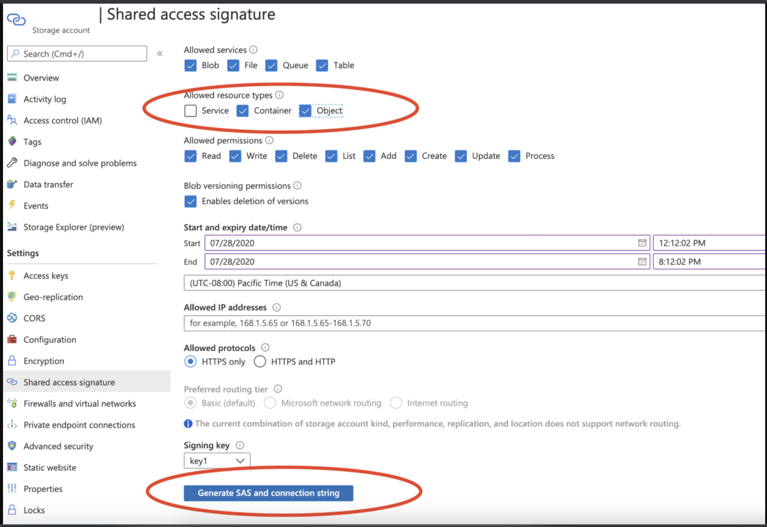
FIGURE 51 Creating a SAS token from a storage account in Azure
Open the Azure Cloud Shell and start a bash shell:
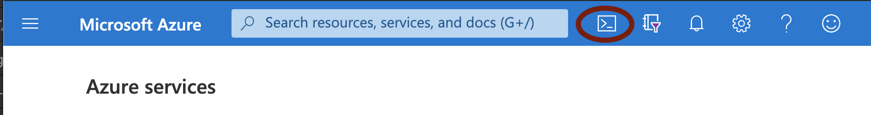
FIGURE 52 Starting the Azure Cloud Shell
In the Azure Cloud shell, use azcopy to copy the Gateway VHD image file into your storage account. For example, use the following syntax:
azcopy copy '<URL to VHD file>' 'https://<MyStorageAccount>.blob.core.windows.net/<Container_Name>/<VHD filename><SAS-Token>''
Replace the angled-bracket elements with the details gathered in previous steps. For example:
azcopy copy 'https://pulseztaeurope.blob.core.windows.net/gateway/PSA-V-HYPERV-ZTA-189.1-SERIAL-hyperv.vhd' 'https://MyStorage.blob.core.windows.net/gateway/PSA-V-HYPERV-ZTA-189.1-SERIAL-hyperv.vhd?sv=2018-11-12&ss=bfqt&srt=co&sp=rwdlacupx&se=2019-12-29T02:57:39Z&st=2020-07-28T18:57:39Z&spr=https&sig=mJU7WNd9oNY7wcXNOqEOhbYshD9Sxv56rqEl%2FmEuCg4%3D'
After you have completed the above prerequisites, create a Gateway instance using following steps:
Note
For reference, the recommended minimum requirements for a Gateway virtual machine instance in Azure are:
Standard_D2s_v3 (2 vCPU, 8 GB Memory), or
Standard_F4s (4 vCPU, 8 GB Memory)
Access the Azure Management Console and log in using your credentials.
Access the Home > Templates page to view available templates.
Click “+ Add” to add a new template.
In the new template “General” section, enter a template name and description.
In the new template “ARM Template” section, remove the default data and replace with the raw text contents of the nZTA Azure Gateway template JSON file.
Note
Use either the new VNET template JSON file or the existing VNET template JSON file as per your requirements.
Save the new template.
On the Home > Templates page, locate the new Azure Gateway template.
On the context menu for the template, click Deploy.
The Custom Deployment page appears.
On the Custom Deployment page, enter any required details for the Gateway deployment.
Resource Group: Specify the resource group name in which the Gateway needs to be deployed, or create a new group.
Location: Specify the region in which the Gateway instance is deployed.
nZTA Storage Account Name: Specify the storage account you created earlier where the Gateway image is held.
nZTA Storage Account Resource Group: Specify the resource group you created earlier.
nZTA Image Location URI: Enter the full URI for the Gateway template image VHD file you copied to your storage account earlier.
nZTA VM Name: Enter a suitable name for your Gateway instance. Pulse recommends matching the Gateway name used during the process of creating the Gateway record on the Controller.
nZTA Config: Paste in the raw text of your Gateway definition file. To obtain the Gateway definition file, see the process described earlier in this section.
SSH Public Key: Specify your SSH key pair name.
If required, update the labels for the instance:
Update the Dns Label Prefix Ext if required. For example, “azuregwext”.
Update the Dns Label Prefix Mgmt if required. For example, “azuregwmgmt”.
Update the Existing Vnet Name if required.
Update the Existing Internal Subnet if required. For example: “InternalNW”.
Update the Existing External Subnet if required. For example: “ExternalNW”.
Update the Existing Management Subnet if required. For example: “ManagementNW”.
For Load Balancer Configuration, If you plan to deploy multiple Gateways inside a Gateway Group, select “Yes” to deploy a new internet-facing Public Standard Load Balancer instance alongside the Gateway. Select “No” to launch only this Gateway instance.
Note
This option is applicable only for new VNET templates.
If you elect to launch a load balancer, the following pre-configuration is applied:
A Standard SKU Public IP address is assigned to the Load Balancer.
A Backend Pool is created and the deployed Gateway is associated with the pool through it’s external network interface.
A health probe is configured on TCP port 443.
Load balancing rules are configured.
After you have deployed the Gateway and Load Balancer, you must return to the Tenant Admin Portal on the Controller and update the Gateway Group Load Balancer IP ADDRESS setting to be the Load Balancer’s public IP address.
If you want to configure the Load Balancer to balance across further Gateway instances from the Gateway Group, you must deploy each subsequent Gateway into the same Resource Group through the use of existing VNET templates and then update the Load Balancer’s Backend Pool.
Note
With new VNET templates, a NAT gateway is deployed for routing outbound Internet traffic from the Gateway’s internal network interface in order for the Gateway to be able to reach the Controller.
Note
Public IP addresses are not automatically assigned to any of your Gateway’s network interfaces. If you are deploying a Gateway into an existing VNET, in order for the Gateway to be able to reach the Controller from it’s internal network interface, make sure you allow outbound Internet traffic from the Private Subnet for the deployed Gateway.
To learn more about high availability and Gateway Groups, see the Tenant Admin Guide.
Agree to the terms and conditions.
Click Purchase to start the creation of the Gateway.
A window displays the status of the process, starting with Deployment in Progress.
(Optional) Click the Deployment in Process hyperlink to view a status page for the process.
Wait until the process completes.
Ensure that your Azure Security Groups support the IP addresses allocated to the Gateway instance. Please refer to Azure’s own documentation for full details.
(This step is required only if you have not deployed your Gateway with a Load Balancer or NAT at the front-end) Public IP addresses are not automatically assigned to any of the Gateway’s network interfaces. Therefore, before your client devices can connect to the new Gateway instance from the Controller, you must associate a new Public IP address with the external interface of the Gateway. Then, update the Controller’s Gateway Public IP address setting to match this address (in the Secure Access > Gateways Overview page, select your new Gateway, then click the Configuration tab and locate IP Settings).
In the Secure Access > Gateways > Gateways List page, make sure the new Gateway has a confirmed status of Connected.
This completes the Azure Gateway registration process. Your enrolled client devices should now be able to connect to the Gateway.
Note
After you have registered a Gateway, you can configure it (or the Gateway Group to which it belongs) as the default Gateway if required. See the Tenant Admin Guide for details.
Workflow: Creating a Gateway in KVM/OpenStack
This workflow leads you through the process for setting up a KVM Gateway in OpenStack. It contains two main procedures, in sequence:
Preparing to create a KVM gateway, see Preparing to Create a KVM Gateway.
Creating the gateway record in the Controller, see Adding a KVM Gateway in nSA.
Preparing Metadata for OpenStack, see Preparing Metadata for OpenStack.
Creating the KVM Gateway virtual machine instance in OpenStack, see Creating the KVM Gateway Virtual Machine Instance in OpenStack.
After these steps have been completed successfully, the Controller and Gateway establish communication with each other.
Preparing to Create a KVM Gateway
Before you start, make sure you have the following information and files:
An identifying name for the Gateway
The public IP address for the Gateway. This is the IP address at which clients can externally reach the Gateway instance.
The Gateway geographic location
(Optional) The name of the Gateway Group to which you want to add this new Gateway record. To learn more about Gateway Groups, see the Tenant Admin Guide.
Additionally, to manually specify KVM Gateway network interface settings:
The primary (and optional secondary) DNS server IP address, and search domain.
The required internal/private subnetworks must already be defined on OpenStack. Please refer to the OpenStack documentation for details.
The required external subnetworks must already be defined on OpenStack. Please refer to the OpenStack documentation for details.
(Optional) Any required management subnetwork must already be defined on OpenStack. Please refer to the OpenStack documentation for details.
The Gateway KVM template: https://pulsezta.blob.core.windows.net/gateway/ISA-V-KVM-ZTA-22.3R4-883.1.zip
Note
Download a copy of the KVM template ZIP file. Then fully unpack the ZIP file, including any compressed .gz files inside, it to a local workstation. Make sure that the resulting file set is accessible from the OpenStack Console.
Note
You can also choose to download this file from the Gateways Overview page of the Tenant Admin Portal. The opportunity to do this occurs later in this process.
Credentials for the OpenStack Console.
Note
These credentials must include sufficient permissions to create a virtual machine from a template image.
After you have all required information, you can set up a nZTA KVM gateway, see Adding a KVM Gateway in nSA.
Adding a KVM Gateway in nSA
To set up a nZTA KVM Gateway, perform the following steps:
Log into the Tenant Admin Portal using the credentials provided in your welcome email. Two outcomes are possible:
On unconfigured nZTA systems, the Secure Access Setup (Onboarding) wizard appears. In this case, click Add Gateway.
On configured nZTA systems, the Network Overview page appears. In this case:
From the nZTA menu, click the Secure Access icon, then select Gateways > Gateway List.
The Gateways List page appears, showing the full list of Gateway Groups and standalone Gateways currently configured on the Controller.
To add a new Gateway, select Create from the top-right:
FIGURE 53 Add a new Gateway or Gateway Group
In the drop-down menu, click Create ZTA Gateway.
In both cases, the Gateway Network Configuration dialog appears.
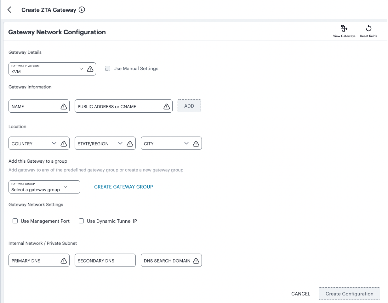
FIGURE 54 Gateway Network Configuration
Note
To learn more about the settings on this page, see the Tenant Admin Guide.
For Gateway Platform, select “KVM”.
Enter a Name for the Gateway.
Enter one or more Public Address or CNAME (Public IP address or CNAME) for the Gateway. Select Add to add each entry to the list.
Select a geographic Location for the Gateway.
(Optional) Select a Gateway Group to which the new Gateway is to be added.
(Optional) Select the Use Management Port check box to use management network ports for nZTA traffic rather than internal ports.
Note
When the management port is enabled, the Controller will still use the internal port for DNS resolution. If the internal DNS cannot resolve the Controller domain, the internal interface will require internet access.
(Optional) Select the Use Dynamic Tunnel IP check box to configure a pool of IP addresses that are dynamically mapped to client sessions with this Gateway, such that user traffic from the Gateway to an application can be identified as originating from a specific client.
The Custom IP Pool dialog appears:
FIGURE 55 Gateway Network Configuration - Custom IP Pool settings
Note
Dynamic Tunnel IP addresses are not supported in Gateway Groups.
Use the Assignable Custom IPv4 Address field to enter an IP address and subnet (in the range 8-28) in CIDR notation, then click Add. Repeat this step for each address/subnet you want to use.
Enter the Primary DNS IP address for the Gateway.
(Optional) Enter the Secondary DNS IP address for the Gateway.
Enter the DNS Search Domain for the Gateway.
Note
Make sure the specified DNS service can resolve the IP address of your Controller. Issues here can cause registration of the Gateway with the Controller to fail.
To add a Gateway definition based on the settings you specified in this dialog, select Create Configuration.
After you complete the first part of this workflow, an unregistered Gateway record is created on the Controller. This Gateway record can be seen on the Gateways > Gateways List page.
You can now prepare your metadata, see Preparing Metadata for OpenStack.
Preparing Metadata for OpenStack
The preparation of metadata for use on OpenStack currently requires some manual steps:
Log into nZTA and access the Gateways > Gateways List page.
On the Gateways List page, select your new Gateway and click the Download icon to obtain a copy of the Gateway definition file.
FIGURE 56 The Download Icon
Specify a save location for your Gateway definition file.
Note
The Gateway definition file is valid for 24 hours. If this period expires, you must replace the Gateway to generate a new Gateway definition file.
(Optional) If you have not yet downloaded the latest version of your Gateway VM file, click the Download icon and select Download gateway VM image. Save the archive file and unpack to a local workstation. Make sure the resulting file set is accessible from the OpenStack Management Console.
View the gateway definition file in a text editor.
Start a separate text editor file, and paste the following template text block into it:
<pulse-config>
   <config-download-url>
      '<insert vaConfigURL value here>'
   </config-download-url>
   <appliance-id>
      <insert vaApplianceID value here>
   <secondary-dns>
      <insert vaSecondaryDNS here>
   </secondary-dns>
   <primary-dns>
      <insert vaPrimaryDNS here>
   </primary-dns>
   <dns-domain>
      <insert vaDnsSearchDomain here>
   </dns-domain>
   </appliance-id>
   <cert-common-name>
      <insert vaCommonName value here>
   </cert-common-name>
   <accept-license-agreement>
      y
   </accept-license-agreement>
   <controller-enrolled-hostname>
      <insert vaControllerEnrolledHostname value here>
   </controller-enrolled-hostname>
   <dns-search-domain>
      <insert vaDnsSearchDomain value here>
   </dns-search-domain>
   <controller-hostname>
      <insert vaControllerHostname value here>
   </controller-hostname>
</pulse-config>
For each parameter block in the template text block file:
Locate the required metadata property for the line.
For example, in the following block:
<appliance-id>
   <insert vaApplianceID value here>
</appliance-id>
You require the vaApplianceID value from the gateway definitions file.
Locate the required value in the gateway definitions file.
For example, the vaApplianceID value is 99ce3aa3c9494cbabb51c085c9c3f6ad.
Copy and paste this value from the gateway definitions file into the template text file.
For example, the <appliance-id> block will now read as follows:
<appliance-id>
   99ce3aa3c9494cbabb51c085c9c3f6ad
</appliance-id>
Note
You do not need to change the <accept-license-agreement> block, and can retain its y setting.
After you have added all required text to the template text file, save that file for use in the next section.
You can now create a KVM gateway VM in Openstack, see Creating the KVM Gateway Virtual Machine Instance in OpenStack.
Creating the KVM Gateway Virtual Machine Instance in OpenStack
To create a KVM VM instance in OpenStack:
Access the OpenStack Management Portal, either from a client or a web browser, and log in using your OpenStack credentials.
In the OpenStack console, the Overview page appears.
In the left menu, click Compute > Images.
The Images page appears. This shows a list of images.
Above the list of images, click Create Image.
The Create Image wizard appears. In this wizard, you upload a KVM gateway image for use.
Under Image Details:
Enter an Image Name. Typically, this incorporates a version number. For example, ZTA_GWY_100.
Enter an Image Description. For example: ZTA KVM Image.
Under Image Source, click Browse and select the unpacked KVM disc image file. Then, click Format and select QCOW2 - QEMU Emulator.
Under Image Requirements, set Minimum Disk (GB) to 40 and Minimum RAM (KB) to 2048.
Set Visibility Setting as required. Public will enable the image to be used in other projects. Private will not.
Set Image Sharing as required.
Use the default settings for all other properties.
Click Next.
The Metadata page of the wizard appears. No action is required on this page, all properties can use their default settings.
Click Create Image.
The wizard closes, and the new KVM gateway image is added to the Images page.
Wait until the image has been uploaded and processed and shows as Active.
Note
The upload image process typically takes 15-20 minutes.
After the image has uploaded and is Active, click its Launch button.
The first page of the Launch Instance wizard appears. In this wizard, you create a KVM gateway instance.
Under Details:
Enter an Instance Name. This will be the displayed name of the gateway in nZTA.
Enter a Description for the KVM gateway. For example ZTA KVM Gateway.
Use the default settings for all other properties.
Click Next.
The Source page of the wizard appears. This page lists the selected disk image and selected/default settings for the instance. No action is required on this page, all properties can use their displayed settings.
Click Next.
The Flavor page of the wizard appears. This page lists the available types of gateway you can create.
Locate the PSA3000-V entry and click its “up arrow” button to select it.
Click Next.
The Networks page of the wizard appears. This page lists the available networks (and associated subnetworks) for the gateway. It enables you to select the required subnetworks for your gateway.
In the available list, locate the required subnetworks.
For example, you may require a subnetwork for internal ports and a subnetwork for external ports, but not a subnetwork for management interfaces.
Note
If the required subnetworks do not yet exist, you must define them. Please refer to the OpenStack documentation for details of this process.
Click the “up arrow” button for each subnetwork to select it.
Note
For each selected subnetwork, a fixed IP address is added automatically to the gateway. These appear later in this process, so that they can be assigned to floating IP addresses.
Click Next.
The Network Ports page of the wizard appears. No action is required on this page, all properties can use their displayed settings.
Click Next.
The Security Groups page of the wizard appears. No action is required on this page, all properties can use their displayed settings.
Click Next.
The Security Groups page of the wizard appears. No action is required on this page, all properties can use their displayed settings.
Note
If there is no default security group defined, you must define one. Please refer to the OpenStack documentation for details of this process.
Click Next.
The Key Pair page of the wizard appears. No action is required on this page, all properties can use their displayed settings.
Click Next.
The Configuration page of the wizard appears. This page enables you to configure the gateway instance using metadata you prepared earlier, see Adding a KVM Gateway in nSA.
Open your template text file and copy the entire text block that starts with
<pulse-config>and ends with</pulse-config>.Paste the text block into the Customization Script block.
Note
You cannot directly paste metadata for your gateway from nZTA. You must prepare a suitable text block from the metadata, see Adding a KVM Gateway in nSA.
Enable the Configuration Drive check box.
Click Launch Instance.
The wizard closes, and the new KVM gateway instance is added.
Access the Instances page.
The new KVM gateway instance is listed on this page.
Wait until the Power State of the gateway instance is Running.
Note
This process may take several minutes.
After the instance state changes to Running, make a note of the subnetworks and their automatically-assigned fixed IP addresses in the IP Address column for the instance. For example:
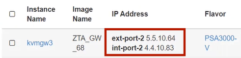
FIGURE 57 Unassociated KVM Ports
In this example, floating IP addresses are listed after the fixed IP addresses, so all are unassociated:
The fixed IP address on the int-port-2 subnetwork is 4.4.10.83.
The fixed IP address on the ext-port-2 subnetwork is 5.5.10.64.
Access the Network > Floating IPs page.
The Floating IPs page shows the floating IP addresses associated with your account. Both associated and unassociated floating IP addresses are listed.
Note
Associated floating IPs have a Mapped Fixed IP Address listed.
Identify an unassociated floating IP address that you want to associate with a fixed IP address.
Click the Associate button for the fixed IP address.
The Manage Floating IP Associations dialog appears.
Select a fixed port to be associated for the selected floating IP address.
Click Associate to conform the association.
Repeat the association process until each of the fixed IP addresses for your gateway instance is associated with a floating IP address.
Wait until the status of these floating IP addresses all show as Active.
Return to the Compute > Instances page.
This page now shows a fixed IP address associated with floating IP address for each port. For example:
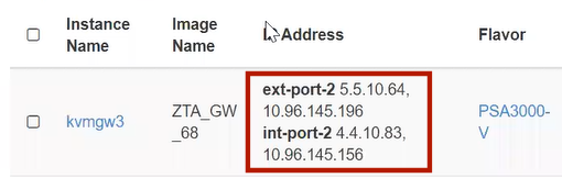
FIGURE 58 Associated KVM Ports
Click the Console tab.
A console monitor view shows the ongoing boot-up process for the instance.
Wait until the instance shows a screen similar to the following:
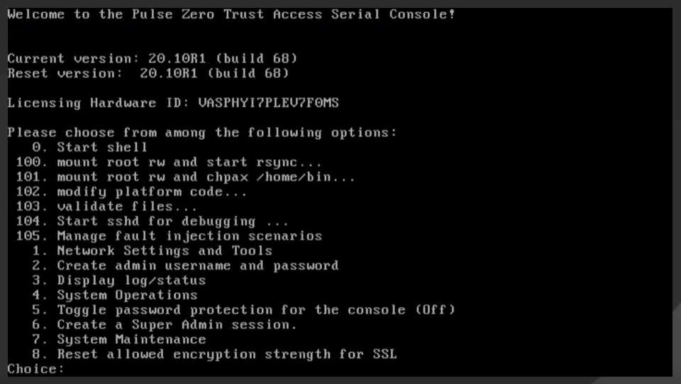
FIGURE 59 KVM Instance Console Monitor
Return to the Gateways List page on the Controller.
Locate the new Gateway record in the list and confirm that its status has updated to Connected. For example:
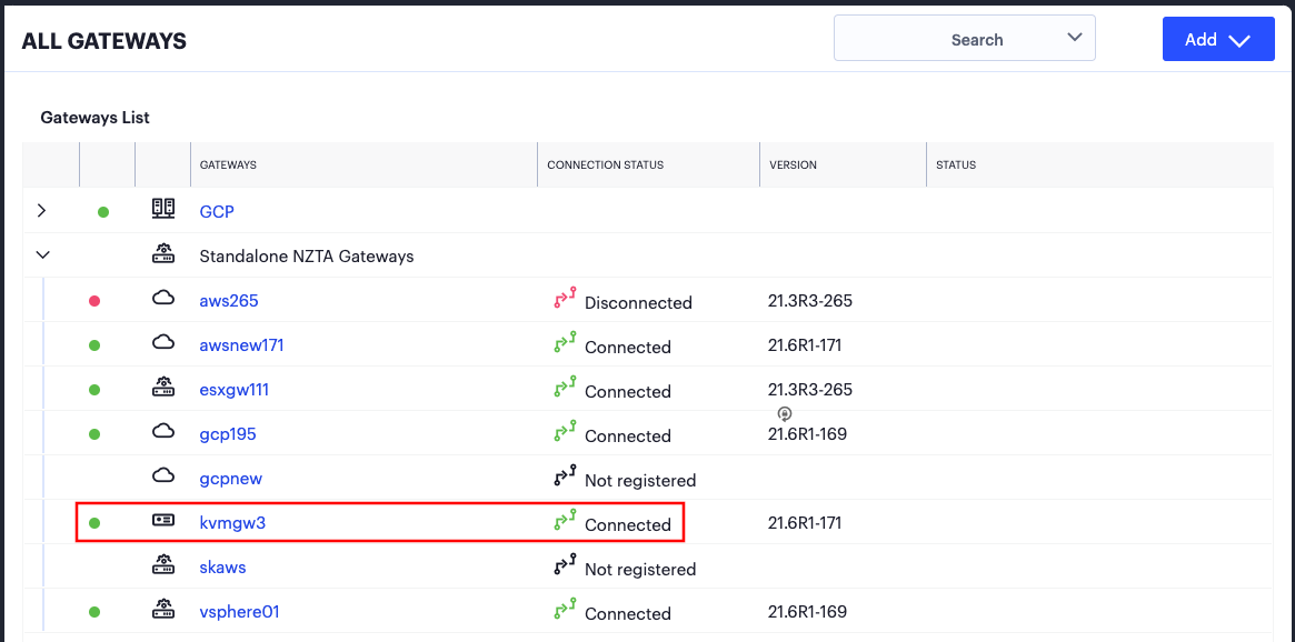
FIGURE 60 KVM Gateway Connected
Note
After you have registered a Gateway, you can configure it (or the Gateway Group to which it belongs) as the default Gateway if required. See the Tenant Admin Guide for details.
Workflow: Creating a Gateway in Google Cloud Platform
This workflow leads you through the processes for setting up a Gateway on the Google Cloud Platform (GCP). These processes must be performed in sequence:
Preparing to create a GCP gateway, see Preparing to Create a GCP Gateway.
Creating the gateway record in the Controller, see Adding a GCP Gateway in nSA.
Downloading Metadata for Google Cloud Platform, see Downloading Metadata for Google Cloud Platform.
Uploading the GCP Image onto the Google Cloud Platform, see Uploading the GCP Virtual Machine Image onto the Google Cloud Platform.
Creating a VM Instance of the GCP image. Either:
Creating a VM Instance of the Uploaded GCP Image Manually, see Creating a VM Instance of the Uploaded GCP Image Manually.
Creating a VM Instance of the Uploaded GCP Image Using a Script/Template, see Creating a VM Instance of the Uploaded GCP Image Using a Script/Template.
Completing the Configuration of the Controller, see Completing the Configuration of the Controller.
After these steps have been completed successfully, the Controller and Gateway establish communication with each other.
Preparing to Create a GCP Gateway
Before you start, make sure you have the following information and files:
An identifying name for the Gateway.
The public IP address for the Gateway. This is the IP address at which clients can externally reach the Gateway instance, such as an LB/NAT or Datacenter network forward rules.
Note
If you want Google Cloud platform to allocated a public IP address automatically, you can use a dummy IP address (for example, 1.1.1.1) when you create the Gateway on nZTA. You must then update the Controller with the allocated public IP address afterwards.
The Gateway geographic location.
(Optional) The name of the Gateway Group to which you want to add this new Gateway record. To learn more about Gateway Groups, see the Tenant Admin Guide.
Note
A Gateway Group may have a defined public IP address, which you can specify during the creation of the Gateway.
Additionally, to manually specify GCP Gateway network interface settings:
The primary (and optional secondary) DNS server IP address, and search domain.
The required internal/private subnetworks must already be defined on Google Cloud Platform, including firewall settings. All required firewall settings for this interface are shown below.
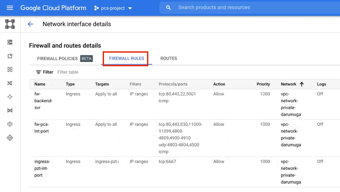
FIGURE 61 Internal/Private Firewall Rules
Refer to the Google Cloud Platform documentation for details.
The required external/public subnetworks must already be defined on Google Cloud Platform, including firewall settings. All required firewall settings for this interface are shown below.
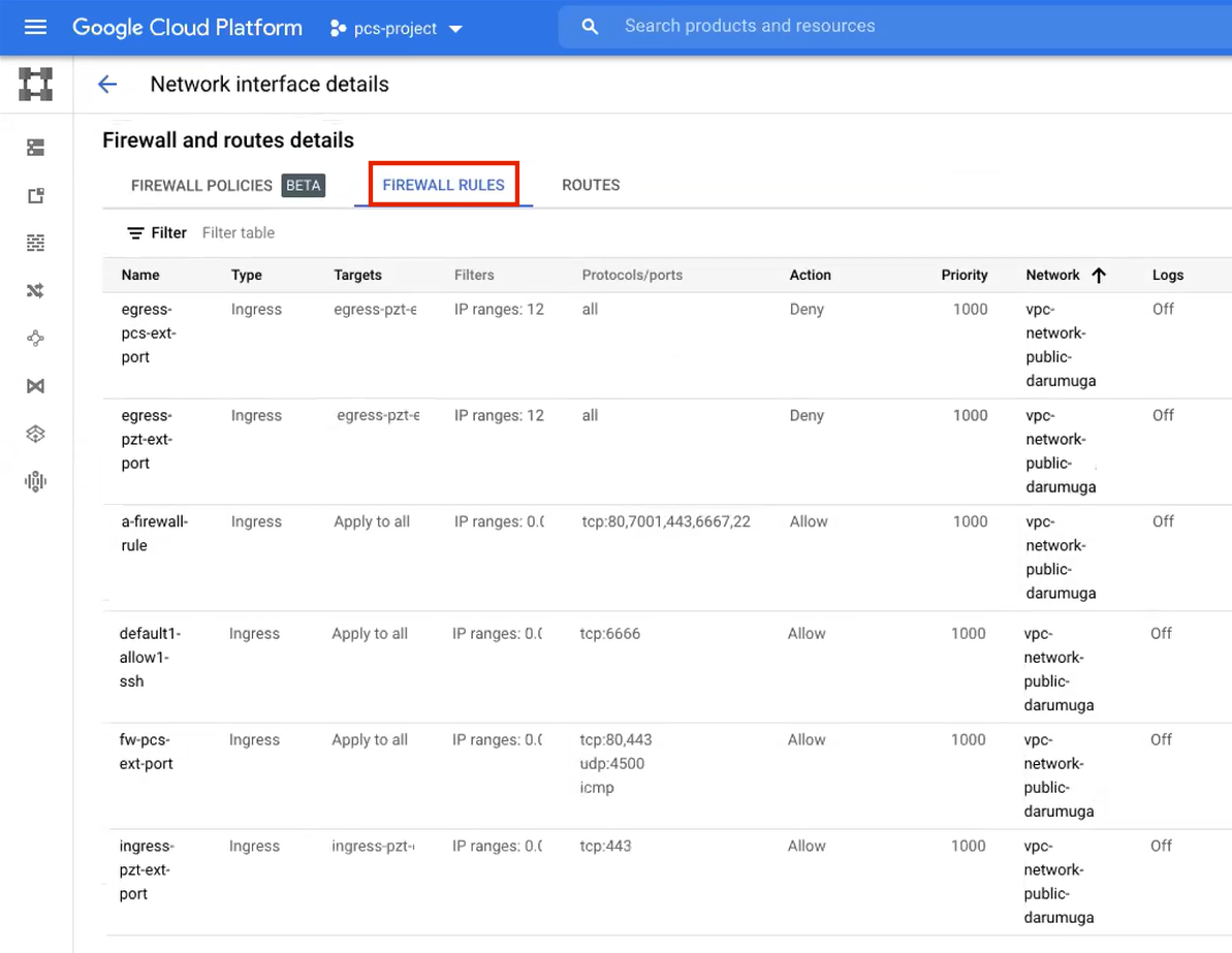
FIGURE 62 External/Public Firewall Rules
Refer to the Google Cloud Platform documentation for details.
(Optional) Any required management subnetwork must already be defined on Google Cloud Platform, including firewall settings. All required firewall settings for this interface are shown below.
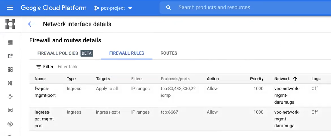
FIGURE 63 Management Firewall Rules
Refer to the Google Cloud Platform documentation for details.
The ZTA Gateway GCP virtual machine image: https://pulsezta.blob.core.windows.net/gateway/ISA-V-GCP-ZTA-22.3R4-883.1.tar.gz
Note
Download a copy of the GCP Gateway image as a compressed TAR archive file, then decompress the archive to a local workstation. Make sure that the resulting file set is accessible from the Google Cloud Platform Console.
Note
You can also choose to download the Gateway image through the Gateways Overview page of the Tenant Admin Portal after you have defined the Gateway record. The opportunity to do this occurs later in this process.
(Optional) GCP Gateway YAML templates, suitable for automating the creation of your GCP VM instances. Choose from:
To deploy in an existing VPC:
https://pulsezta.blob.core.windows.net/gateway/templates/GCP/23-2-883/ivanti-zta-2-nics-existing-vpc.zip
https://pulsezta.blob.core.windows.net/gateway/templates/GCP/23-2-883/ivanti-zta-3-nics-existing-vpc.zipTo deploy in a new VPC:
https://pulsezta.blob.core.windows.net/gateway/templates/GCP/23-2-883/ivanti-zta-2-nics-new-vpc.zip
https://pulsezta.blob.core.windows.net/gateway/templates/GCP/23-2-883/ivanti-zta-3-nics-new-vpc.zip
Note
You can also choose to download Gateway templates through the Gateways Overview page of the Tenant Admin Portal after you have defined the Gateway record. The opportunity to do this occurs later in this process.
Credentials for the Google Cloud Platform Console.
Note
These credentials must include sufficient permissions to create a virtual machine from a template image.
After you have all required information, you can set up a nZTA GCP gateway, see Adding a GCP Gateway in nSA.
Adding a GCP Gateway in nSA
To set up a nZTA GCP Gateway, perform the following steps:
Log into the Tenant Admin Portal using the credentials provided in your welcome email. Two outcomes are possible:
On unconfigured nZTA systems, the Secure Access Setup (Onboarding) wizard appears. In this case, click Add Gateway.
On configured nZTA systems, the Overview of Network page appears. In this case:
From the nZTA menu, click the Secure Access icon, then select Gateways > Gateway List.
The Gateways List page appears, showing the full list of Gateway Groups and standalone Gateways currently configured on the Controller.
To add a new Gateway, select Create from the top-right:
FIGURE 64 Add a new Gateway or Gateway Group
In the drop-down menu, click Create ZTA Gateway.
In both cases, the Gateway Network Configuration dialog appears.

FIGURE 65 Gateway Network Configuration
Note
To learn more about the settings on this page, see the Tenant Admin Guide.
For Gateway Platform, select “Google Cloud Platform”.
Enter a Name for the Gateway.
Enter one or more Public Address or CNAME (Public IP address or CNAME) for the Gateway. Select Add to add each entry to the list.
Note
If you want Google Cloud Platform to allocate a public IP address automatically, you can use a dummy IP address (for example, 1.1.1.1) at this point. You must then update the Controller with the allocated public IP address after the GCP VM instance is created.
Select a geographic Location for the Gateway.
(Optional) Select a Gateway Group to which the new Gateway is to be added.
Note
A Gateway Group may have a defined public IP address, which you can specify as the Public Address, see above.
(Optional) Select the Use Management Port check box to use management network ports for nZTA traffic rather than internal ports.
Note
When the management port is enabled, the Controller will still use the internal port for DNS resolution. If the internal DNS cannot resolve the Controller domain, the internal interface will require internet access.
Enter the Primary DNS IP address for the Gateway.
(Optional) Enter the Secondary DNS IP address for the Gateway.
Enter the DNS Search Domain for the Gateway.
Note
Make sure the specified DNS service can resolve the IP address of your Controller. Issues here can cause registration of the Gateway with the Controller to fail.
To add a Gateway definition based on the settings you specified in this dialog, select Create Configuration.
By completing the Gateway Network Configuration workflow, an unregistered Gateway record is created on the Controller. You can view this Gateway record on the Gateways > Gateways List page.
You can now download your metadata, see Downloading Metadata for Google Cloud Platform.
Downloading Metadata for Google Cloud Platform
The preparation of metadata for use on Google Cloud Platform currently requires some manual steps:
Log into nZTA and access the Gateways > Gateways List page.
Select your GCP Gateway and click the Download icon to obtain a copy of the Gateway definition file.
FIGURE 66 The Download Icon
Specify a save location for your Gateway definition file.
Note
The Gateway definition file is valid for 24 hours. If this period expires, you must replace the Gateway to generate a new Gateway definition file.#
(Optional) If you have not yet downloaded the latest version of your Gateway VM image and optional YAML templates, click the Download icon and select Download gateway VM image. Save the archive file and unpack to a local workstation. Make sure the resulting file set is accessible from the Google Cloud Platform Management Portal.
You can now create a GCP gateway VM in Google Cloud Platform, see Uploading the GCP Virtual Machine Image onto the Google Cloud Platform.
Uploading the GCP Virtual Machine Image onto the Google Cloud Platform
To upload a GCP Gateway virtual machine image into Google Cloud Platform:
Access the Google Cloud Platform Management Portal, either from a client or a web browser, and log in using your Google Cloud Platform credentials.
In the Google Cloud Platform console, select your required project from the pull-down list on the title bar. For example:

FIGURE 67 GCP Select Project
Click the Navigation menu, and then select Cloud Storage > Browser.
A list of GCP storage buckets appears.
Select the bucket into which you wish to place the GCP image.
A page listing the current contents of the bucket appears.
(Optional) Navigate to the required folder within the bucket.
Click Upload Files. For example:
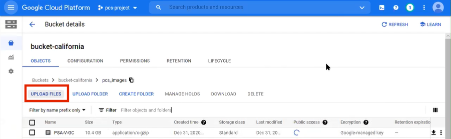
FIGURE 68 GCP Upload Files
An upload dialog appears.
Select the .tar image file archive downloaded from https://pulsezta.blob.core.windows.net/gateway/ISA-V-GCP-ZTA-22.3R4-883.1.tar.gz, and click Open.
Note
If you want to use the provided YAML templates to automate the creation of your VM instance (see Creating a VM Instance of the Uploaded GCP Image Using a Script/Template), select these in addition to the image archive.
The image archive and any selected template files are added to the bucket.
Wait until the upload completes. This may take several minutes.
Start a command line session from the title bar. For example:

FIGURE 69 GCP Upload Files
A command line session starts.
Navigate to the project folder.
Create an image from the ZTA Gateway image archive using the following command:
gcloud compute images create <instance_name> --source-uri=gs://<bucket_name>/<optional_path>/<image_name>.tar --guest-os-features MULTI_IP_SUBNET
For example:
gcloud compute images create ztagcp152 --source-uri=gs://bucket-california/pcs_images/PSA-V-GCP-ZTA-153.1-SERIAL-gcp.tar --guest-os-features MULTI_IP_SUBNET
You can now create a VM instance of the uploaded GCP image. To do this, either:
Perform the task manually, see Creating a VM Instance of the Uploaded GCP Image Manually.
Perform the task with a script/template, see Creating a VM Instance of the Uploaded GCP Image Using a Script/Template.
Creating a VM Instance of the Uploaded GCP Image Manually
This section describes how to manually create a virtual machine instance of the ZTA Gateway image inside Google Cloud Platform. You can also perform this process automatically using a script/template, see Creating a VM Instance of the Uploaded GCP Image Using a Script/Template.
Click the Navigation menu, and then select Compute Engine > Images.
The Images page appears. For example:
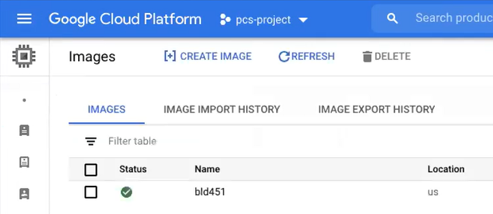
FIGURE 70 GCP Images Page
Locate the new image in the list of images.
At the end of the image entry, click the action menu and select Create Instance.
The Create Instance page appears. For example:
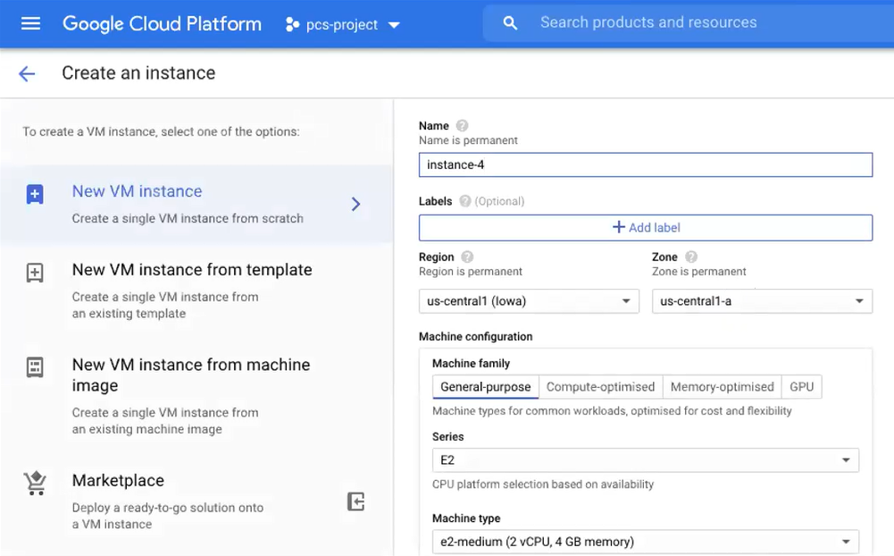
FIGURE 71 GCP Create Instance
On the Create Instance page:
Enter a Name for the new instance.
Select a Region and Zone.
Under Machine configuration:
For Series, select N1.
For Machine Type, select a minimum of n1-standard-2.
For Boot Disk, confirm that the correct image is already selected.
For Firewall, select the required HTTP/HTTPS options.
Expand the Management, security, disks, networking, sole tenancy options.
Select the Management tab.
Under Metadata:
For Key, enter pulse-config.
For Value, paste the text of the metadata file you downloaded earlier.
Select the Networking tab.
Under Network interfaces, click the Edit icon to change the default network interface selection.
The Network interface options appear.
Under Network interface, specify a private (internal) network interface:
For Network, select the required private VPC.
For Subnetwork, select the required subnetwork.
Click Done to confirm the settings for the private network interface.
Under Network interfaces, click Add network interface.
The Network interface options appear.
Under Network interface, specify a public (external) network interface:
For Network, select the required public VPC.
For Subnetwork, select the required subnetwork.
Click Done to confirm the settings for the public network interface.
(Optional) Click Add network interface and specify a management network interface.
Click Create to confirm the settings and instantiate a VM instance of the image.
The VM Instances page appears. This page shows the new VM instance of the image. For example:
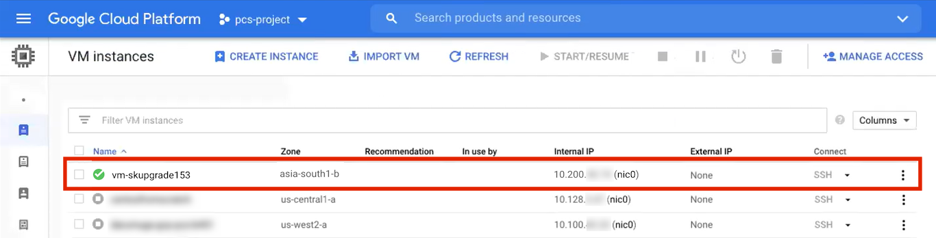
FIGURE 72 GCP Create Instance
On the VM Instances page, wait until the creation of the VM instance completes. This may take several minutes.
After the VM instance is created, click on it in the list of VM instances.
The VM instance details page appears for the instance.
Confirm the details for the VM instance, including the number of network interfaces.
Make a note of the public IP address of the EXT interface (typically, this is nic1. This is required inside nZTA.
Under Network interfaces, confirm that the firewall settings from your VPCs are present for your specified network interfaces:
Click nic0. A summary page for this network interface appears.
Under Firewall and route details, click the Firewall Rules tab and confirm that the following firewall rules are defined.
FIGURE 73 NIC0 Firewall Rules
Click nic1. A summary page for this network interface appears.
Under Firewall and route details, click the Firewall Rules tab and confirm that the following firewall rules are defined.
FIGURE 74 NIC1 Firewall Rules
(Optional) Click nic2. A summary page for this optional network interface appears.
Under Firewall and route details, click the Firewall Rules tab and confirm that the following firewall rules are defined.
FIGURE 75 NIC2 Firewall Rules
The VM instance details* page, click Connect to serial console
A console monitor view (in a separate browser tab) shows the ongoing boot-up process for the instance.
Wait until the instance boot up is complete, and shows a screen similar to the following:
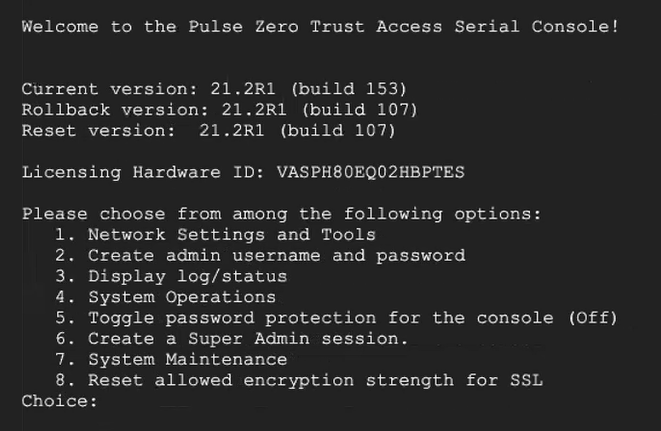
FIGURE 76 GCP Instance Console Monitor
You can then complete this process by updating the Gateway details on the Controller, see Completing the Configuration of the Controller.
Creating a VM Instance of the Uploaded GCP Image Using a Script/Template
This section describes how to automatically create a virtual machine instance of the ZTA Gateway image inside Google Cloud Platform using a script/template. You can also perform this process manually, see Creating a VM Instance of the Uploaded GCP Image Manually.
Ivanti provides YAML-based templates to create an instance of the ZTA Gateway image in the following configurations:
Two network interfaces in an existing VPC.
Three network interfaces in an existing VPC.
Download:
https://pulsezta.blob.core.windows.net/gateway/templates/GCP/23-2-883/ivanti-zta-2-nics-existing-vpc.zip
https://pulsezta.blob.core.windows.net/gateway/templates/GCP/23-2-883/ivanti-zta-3-nics-existing-vpc.zipTwo network interfaces in a new VPC.
Three network interfaces in a new VPC.
Download:
https://pulsezta.blob.core.windows.net/gateway/templates/GCP/23-2-883/ivanti-zta-2-nics-new-vpc.zip
https://pulsezta.blob.core.windows.net/gateway/templates/GCP/23-2-883/ivanti-zta-3-nics-new-vpc.zip
Note
You can obtain these templates through the links given here, or as part of the archive file set provided through the Download link on the Gateways Overview page in the Tenant Admin Portal after you have defined a Gateway record.
To use a template:
Download the required template archive file to your local workstation.
Unpack the downloaded archive file to a location that is accessible from Google Cloud Platform. Each archive contains three files. For example, for the two-interface (existing VPC) version of the archive:
pulsesecure-zta-2nics-existing-vpc.jinja
pulsesecure-zta-2nics-existing-vpc.jinja.scheme
pulsesecure-zta-2nics-existing-vpc.yaml
Edit the YAML file
propertiessection to reflect your project and instance requirements, including theuser_dataproperty.An example of an existing VPC YAML file is provided here:
imports:
  - path: pulsesecure-zta-2-nics-existing-vpc.jinja
resources:
  - name: my-vm
    properties:
      project: zta-gw-263035
      email: [email protected]
      region: asia-south1
      zone: asia-south1-b
      image: ztagcp123
      machine_type: n1-standard-2
      int_network:
      ext_network:
      int_subnetwork:
      ext_subnetwork:
      user_data:
    type: pulsesecure-zta-2-nics-existing-vpc.jinja
An example of a new VPC YAML file is provided here:
imports:
  - path: pulsesecure-zta-2-nics-new-vpc.jinja
resources:
  - name: my-vm
    properties:
      deploy_with_lb: yes
      project: zta-gw-263035
      email: [email protected]
      region: asia-south1
      zone: asia-south1-b
      image: ztagcp123
      machine_type: n1-standard-2
      user_data: <pulse-config><primary-dns>8.8.8.8<\primary-dns> ...
      int_cidr: 192.0.2.0/24
      ext_cidr: 192.0.2.0/24
    type: pulsesecure-zta-2-nics-new-vpc.jinja
Note
Where you are specifying a new VPC for your virtual machine instance, make sure you use properties (for example, networking settings) that do not conflict with an existing VPC.
Save the YAML file.
On the Google Cloud Platform, start a command line session from the title bar. For example:
FIGURE 77 GCP Upload Files
A command line session starts.
Select the required project:
gcloud config set project <project-name>
Within the project folder, create a deploymentmanager folder.
Copy the three script files to this folder.
Create a VM instance from the ZTA Gateway image archive file using the following command:
gcloud deployment-manager deployments create <vm-name> --config <yaml_file>
For example:
gcloud deployment-manager deployments create vm-gcp-123 --config pulsesecure-zta-3-nics-existing-vpc.yaml
Wait until the command completes.
On the VM Instances page, click on the new VM in the list of VM instances.
The VM instance details page appears for the instance.
Confirm the details for the VM instance, including the number of network interfaces.
Make a note of the public IP address of the EXT interface (typically, this is nic1. This is required inside nZTA.
You can now complete this process by updating the Gateway details on the Controller, see Completing the Configuration of the Controller.
Completing the Configuration of the Controller
If you specified a dummy public IP address (for example, 1.1.1.1) when you created the Gateway on the Controller, you now need to update the Controller with the allocated public IP address for the Gateway VM instance on Google Cloud Platform.
Note
You do not need to perform the following procedure if you specified the correct public IP address when you created the Gateway on the Controller, see Adding a GCP Gateway in nSA.
Return to the Gateways List page in the nZTA Tenant Admin Portal.
Locate the new Gateway record in the list and confirm that its status has updated to Connected.
Select the Gateway, and then select Secure Access > Gateways > Configuration.
Under Gateway Network Settings, delete the current public IP setting and replace it with the public IP address if the nic1 (external) interface for the VM instance.
Note
After you have registered a Gateway, you can configure it (or the Gateway Group to which it belongs) as the default Gateway if required. See the Tenant Admin Guide for details.
Next Steps
After you have defined your user authentication policies, move on to create your device policies. See Creating Device Policies and Device Rules.