Network and Host Administration
Introduction
When you install and initially set up the device, you use the serial port console to set basic network and host settings. To get started, you must use the serial console to configure these settings for the internal interface. You have the option to use the serial console to configure network and host settings for the external interface and the management interface. The network and host settings you configure with the serial port console include:
Once the internal interface has been configured, you can use the admin console Network Settings pages to modify settings for the internal interface, to enable and configure the external interface and the management interface, and to configure or manage advanced networking features, including:
Hostname
IPv6 addresses
VLAN ports
Virtual ports
Route table entries
Host mapping table entries
ARP cache entries
Neighbor discovery cache entries
System date and time (manual configuration) or NTP
Internal Port Configuration
The internal port, also known as the internal interface, handles all LAN requests to resources, listening for Web browsing, file browsing, authentication, and outbound mail requests.
To configure the internal port configuration:
Settings
Log in to the Ivanti Neurons for Secure Access portal as a Tenant Admin. See Logging in to Ivanti Neurons for Secure Access.
Use the Gateway Switcher and select Ivanti Connect Secure.
From the Ivanti Connect Secure menu, click the Gateways icon, then select Gateways > Gateways List.
The All Gateways page is displayed showing a list of standalone ICS Gateways and Cluster nodes.
From the Standalone ICS Gateways list, click on the gateway link that you want to configure.
On the Ivanti Connect Secure menu, select System > Network > Internal Port > Settings to display the configuration page.
Under IPV4 Settings, assign an IP address, assign a Netmask, and specify the IPv4 address for the default Gateway.
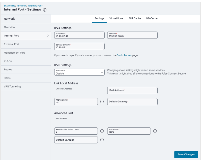
FIGURE 276 Internal Port Configuration
Under IPV6 Settings, select IPV6 Status.
Under Link Local Address, you can see the auto-configured link local address. Specify a routable IPv6 address, Prefix Length, and IPv6 address for the default Gateway.
Under Advanced Port, specify the ARP Ping Timeout, maximum transmission unit, and default VLAN ID for the traffic of this port.
Click Save Changes.
Virtual port - You can use virtual ports to provide different groups of users access to the same system using different IP aliases and domains.
To configure a virtual port:
Select Internal Port > Virtual Ports. Port is Internal Port or External Port.
Click ‘+’ to display the configuration page.
Enter a name for the virtual port.
Enter the IPv4 address and the IPv6 address.
Click Save Changes.
ARP Cache - In IPv4 networking, network nodes use ARP to maintain information about peer network nodes.
To manage the ARP table:
Select Internal Port > ARP Cache. Port is Internal Port, External Port, or Management Port.
Click ‘+’ to display the configuration page.
Enter an IP address, and a MAC address.
Click Save Changes to add an entry.
You can delete all dynamically discovered entries.
ND Cache - In IPv6 networking, network nodes use the Neighbor Discovery Protocol (NDP) to determine the Layer 2 MAC addresses for neighboring hosts and routers.
To manage the neighbor discovery table:
Select Internal Port > ND Cache. Port is Internal Port, External Port, or Management Port.
The Flush NDP Entries deletes all dynamically discovered entries.
External Port Configuration
The external port, also known as the external interface, handles all requests from users signed into Ivanti Connect Secure from outside the customer LAN, for example, from the Internet. Before sending a packet, Ivanti Connect Secure determines if the packet is associated with a TCP connection that was initiated by a user through the external interface. If that is the case, Ivanti Connect Secure sends the packet to the external interface. All other packets go to the internal interface.
To configure the external port configuration:
Settings
Log in to the Ivanti Neurons for Secure Access portal as a Tenant Admin. See Logging in to Ivanti Neurons for Secure Access.
Use the Gateway Switcher and select Ivanti Connect Secure.
From the Ivanti Connect Secure menu, click the Gateways icon, then select Gateways > Gateways List.
The All Gateways page is displayed showing a list of standalone ICS Gateways and Cluster nodes.
From the Standalone ICS Gateways list, click on the gateway link that you want to configure.
On the Ivanti Connect Secure menu, select System > Network > External Port > Settings to display the configuration page.
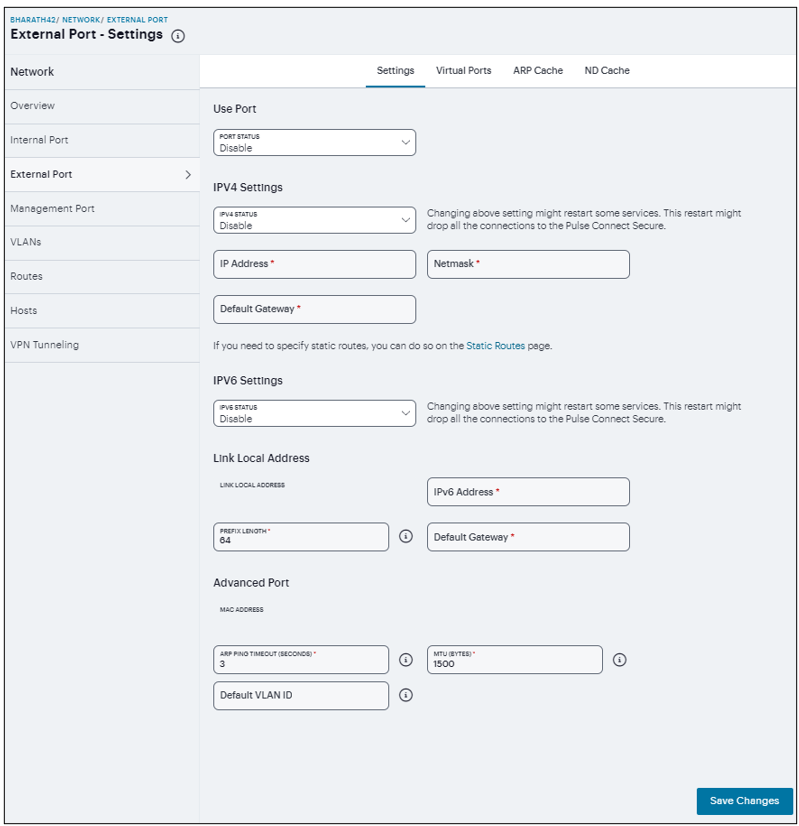
FIGURE 277 External Port Configuration
Enable the Port Status.
Under IPV4 Settings, assign an IP address, a Netmask, and the IPv4 address for the default Gateway.
Under IPV6 Settings, select IPV6 Status.
Under Link Local Address, you can see the auto-configured link local address. Specify a routable IPv6 address, Prefix Length, and IPv6 address for the default Gateway.
Under Advanced Port, specify the ARP Ping Timeout, maximum transmission unit, and default VLAN ID for the traffic of this port.
Click Save Changes.
Virtual Ports - You can use virtual ports to provide different groups of users access to the same system using different IP aliases and domains.
To configure a virtual port:
Select External Port > Virtual Ports. Port is Internal Port or External Port.
Click ‘+’ to display the configuration page. Specify a name for the virtual port, an IPv4 address, and an IPv6 address.
Click Save Changes.
ARP Cache - In IPv4 networking, network nodes use ARP to maintain information about peer network nodes.
To manage the ARP table:
Select External Port > ARP Cache. Port is Internal Port, External Port, or Management Port.
Click ‘+’ and specify an IP address, a MAC address.
Click Save Changes to add an entry.
You can delete all dynamically discovered entries.
ND Cache - In IPv6 networking, network nodes use the Neighbor Discovery Protocol (NDP) to determine the Layer 2 MAC addresses for neighboring hosts and routers.
To manage the neighbor discovery table:
Select External Port > ND Cache. Port is Internal Port, External Port, or Management Port.
The Flush NDP Entries deletes all dynamically discovered entries.
Management Port Configuration
You connect the management port to an Ethernet switch or router that is part of your internal local area network (LAN) and that can connect to your network management infrastructure. When the management port is enabled, the following traffic is directed out the management port: archiving (FTP/SCP), NTP, push config, SNMP, syslog. When the management port is not enabled, that traffic uses the internal port.
To configure the management port:
Log in to the Ivanti Neurons for Secure Access portal as a Tenant Admin. See Logging in to Ivanti Neurons for Secure Access.
Use the Gateway Switcher and select Ivanti Connect Secure.
From the Ivanti Connect Secure menu, click the Gateways icon, then select Gateways > Gateways List.
The All Gateways page is displayed showing a list of standalone ICS Gateways and Cluster nodes.
From the Standalone ICS Gateways list, click on the gateway link that you want to configure.
On the Ivanti Connect Secure menu, select System > Network > Management Port > Settings to display the configuration page.

FIGURE 278 Management Port Configuration
Enable the Port Status.
Under IPV4 Settings, Assign an IP address, a Netmask, and specify the IPv4 address for the default Gateway.
Under IPV6 Settings, select IPV6 Status.
Under Link Local Address, you can see the auto-configured link local address. Specify a routable IPv6 address, Prefix Length, and IPv6 address for the default Gateway.
Under Advanced Port, specify the ARP Ping Timeout, maximum transmission unit, and default VLAN ID for the traffic of this port.
Click Save Changes.
ARP Cache - In IPv4 networking, network nodes use ARP to maintain information about peer network nodes.
To manage the ARP table:
Select Management Port > ARP Cache. Port is Internal Port, External Port, or Management Port.
Click ‘+’ and specify an IP address and a MAC address.
Click Save Changes to add an entry.
You can delete all dynamically discovered entries.
ND Cache - In IPv6 networking, network nodes use the Neighbor Discovery Protocol (NDP) to determine the Layer 2 MAC addresses for neighboring hosts and routers.
To manage the neighbor discovery table:
Select Management Port > ND Cache. Port is Internal Port, External Port, or Management Port.
The Flush NDP Entries deletes all dynamically discovered entries.
VLAN Ports Configuration
Your network design might include VLANs to provide network segmentation. When connected to a trunk port on a VLAN-enabled switch, the system encounters traffic from all VLANs. This is useful for network designs with separate VLANs for separate classes of users or endpoints, and for making the system accessible from all VLANs. You can use RADIUS attributes to place different users in different network segments.
The system supports IEEE 802.1Q VLAN tagging. You must define a VLAN port for each VLAN. The internal port must be assigned to the root system and must be marked as the default VLAN. Routes to servers reachable from the VLAN interfaces must have the next-hop gateway set to the configured gateway for the VLAN interface, and must have the output port defined as the VLAN port.
When you save the configuration for a new VLAN port, the system creates two static routes by default:
The default route for the VLAN pointing to the default gateway.
The interface route to the directly connected network.
To configure an internal VLAN port:
Log in to the Ivanti Neurons for Secure Access portal as a Tenant Admin. See Logging in to Ivanti Neurons for Secure Access.
Use the Gateway Switcher and select Ivanti Connect Secure.
From the Ivanti Connect Secure menu, click the Gateways icon, then select Gateways > Gateways List.
The All Gateways page is displayed showing a list of standalone ICS Gateways and Cluster nodes.
From the Standalone ICS Gateways list, click on the gateway link that you want to configure.
On the Ivanti Connect Secure menu, select System > Network > VLANs > Internal Port to display the configuration page.
Select VLANs > Internal Port.
Click ‘+’, a New VLAN Port -Settings opens.
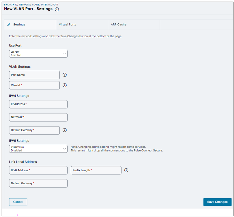
FIGURE 279 VLANS Internal Port Configuration
Enable the Use Port.
Under VLAN Settings, specify a Name that is unique across all VLAN ports and specify a VLAN ID between 1 and 4094.
Under IPV4 Settings, assign an IP address, a Netmask, and specify the IPv4 address for the default Gateway.
Under IPV6 Settings, select the IPV6 Status.
Under Link Local Address, specify a Routable IPv6 address, Prefix Length, and IPv6 address for the default Gateway.
Click Save Changes.
To configure an External VLAN port:
Select VLANs > External Port.
Click ‘+’, a New VLAN Port -Settings opens.
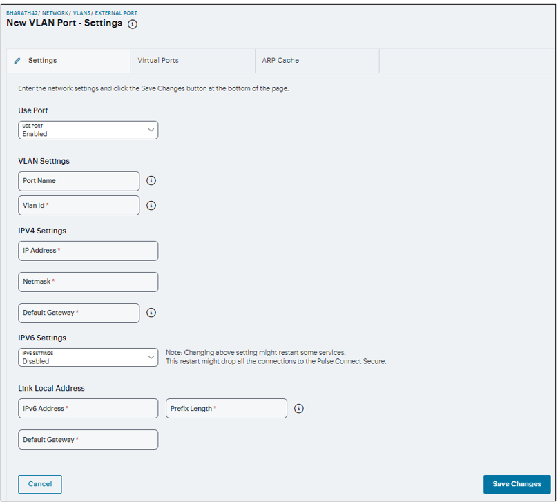
FIGURE 280 VLANS External Port Configuration
Enable the Use Port.
Under VLAN Settings, specify a Name that is unique across all VLAN ports and specify a VLAN ID between 1 and 4094.
Under IPV4 Settings, assign an IP address, a Netmask, and specify the IPv4 address for the default Gateway.
Under IPV6 Settings, select the IPV6 Status.
Under Link Local Address, specify a Routable IPv6 address, Prefix Length, and IPv6 address for the default Gateway.
Click Save Changes.
To configure a Management VLAN port:
Select VLANs > Management Port.
Click ‘+’, a New VLAN Port -Settings opens.
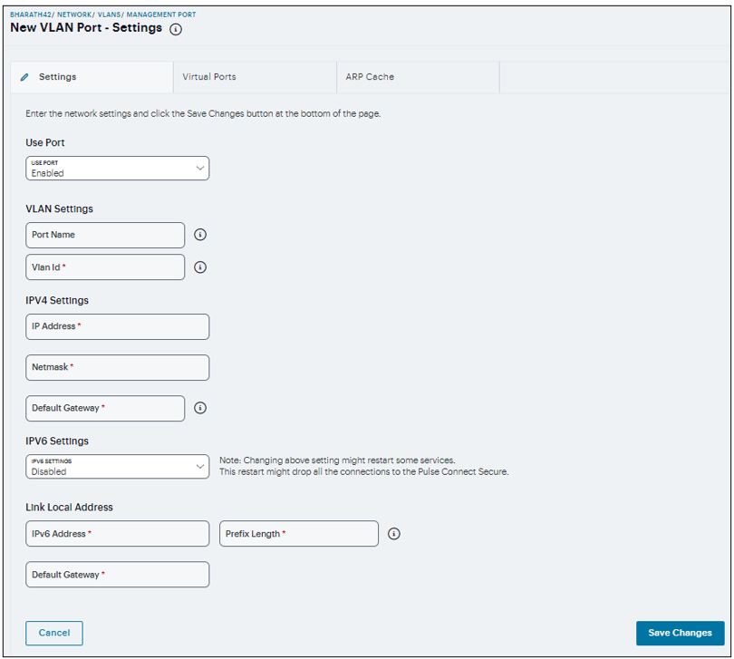
FIGURE 281 VLANS Management Port Configuration
Enable the Use Port.
Under VLAN Settings, specify a Name that is unique across all VLAN ports and specify a VLAN ID between 1 and 4094.
Under IPV4 Settings, assign an IP address, a Netmask, and specify the IPv4 address for the default Gateway.
Under IPV6 Settings, select the IPV6 Status.
Under Link Local Address, specify a Routable IPv6 address, Prefix Length, and IPv6 address for the default Gateway.
Click Save Changes.
Routes Configuration
The system populates the routes table with dynamic, auto-discovered routes. Many networks will not require changes to this routing table. If necessary, you can delete routes or add static routes.
To manage the routes table:
In the Routes page, use the controls to change the display to show the route table for internal, external, or management interfaces; and for IPv4 or IPv6 routes.
Click ‘+’ and complete the configuration to add a route to the table.
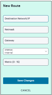
FIGURE 282 Network Routes Configuration
Specify a valid IP address, Gateway, DNS address, and select the Interface and metric.
Click Save Changes.
Hosts Configuration
In general, the system uses the configured DNS servers to resolve hostnames, but it also maintains a local hosts table that can be used for name resolution. The system populates some entries from host-IP address pair settings in your configuration. You can add host-IP address mappings for other hosts that might not be known to the DNS servers used by the system, or in cases where DNS is not reachable.
To configure hosts table:
In the Hosts page, click ‘+’.
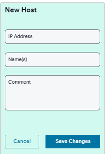
FIGURE 283 Network Hosts Configuration
Specify an IP address, hostname, and comment (a description for the benefit of system administrators).
Click Save Changes.
VPN Tunnel Configuration
The VPN tunneling access option (formerly called Network Connect) provides a VPN user experience, serving as an additional remote access mechanism to corporate resources using Connect Secure. The VPN Tunneling Server uses the filter list to assign IP addresses to clients requesting a VPN client session. A filter is an IP address/netmask combination. For example: 10.11.0.0/255.255.0.0 or 10.11.0.0/16.
To add an IP address to the VPN tunneling filter list:
In the VPN tunneling page, click +, and enter an IP address/netmask combination.
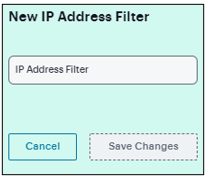
FIGURE 284 Specifying IP Address Filter
In the VPN Tunnel Server IP Address text box, enter the base IP address used by the VPN tunneling server to assign IP addresses to the tunnel interfaces created for VPN Tunneling sessions.
Click Save Changes.
Note
Only change the VPN tunneling server base IP address when instructed to do so by the Ivanti Support team.