System Configuration
Introduction
When you install and initially set up the device, you use the serial port console to set basic network and host settings. To get started, you must use the serial console to configure these settings for the internal interface. You have the option to use the serial console to configure network and host settings for the external interface and the management interface.
Once the internal interface has been configured, you can use the admin console Network Settings pages to modify settings for the internal interface, to enable and configure the external interface and the management interface, and to configure or manage advanced networking features, including:
Hostname
IPv6 addresses
VLAN ports
Virtual ports
Route table entries
Host mapping table entries
ARP cache entries
Neighbor discovery cache entries
System date and time (manual configuration) or NTP
NTP Configuration
You can use the admin console to set the system date and time manually or by configuring a network time protocol (NTP) server. The system supports NTPv4, which is backwards compatible with NTPv3 and NTPv2.
Note
We recommend you use NTP to synchronize the date and time clocks on all network systems. Using NTP obviates issues that might occur with cluster synchronization, network communication that uses time-sensitive protocols, such as SAML, and implementation of time - based policies, such as local authentication server account expiration. In addition, using NTP as a standard in your network rationalizes timestamps in logs, which facilitates reporting and troubleshooting.
To configure NTP:
Log into the nSA as a Tenant Admin.
From the ICS menu, click the Gateways > Gateways List and then select any standalone ICS Gateway or Cluster node.
Navigate to System > NTP displays the System Status page with System Date and Time.
Select your Time Zone. Selecting the appropriate time zone enables the system to automatically adjust the time for Daylight Saving Time changes
Select Time Source.
If Use Pool of NTP Servers is selected, configuring one NTP server is mandatory, but keys are optional. Click Save Changes.
Note
It is not recommended to use only two NTP servers. If more than one NTP server is required, four NTP servers is recommended minimum. Four servers protect against one incorrect timesource.
Note
If you are using NTPv4, specify the symmetric key. The key must be pre-synchronized with the NTP server. For example, if you want to configure NIST’s clock as the NTP server, you must request a key beforehand and have NIST send that key to you.
If Set Time Manually is selected, Specify the Date and Time with Time Slot.
You can click Get from Browser to automatically populate the Date and Time fields. Click Save Changes.
Licensing Mode
You can use either Gateway licenses or nSA Named User licenses. You can switch between these two licensing modes any time. Gateway Licensing mode is same as the existing 9.x Gateway licensing.
To choose the licensing mode:
Log into the nSA as a Tenant Admin.
From the ICS menu, click the Gateways > Gateways List and then select any standalone ICS Gateway and Cluster node.
Navigate to System > Configuration > Licensing > Licensing Summary. The License Summary page shows the two options, Gateway Licensing Mode and nSA Named User Licensing Mode. By default, Gateway Licensing Mode is selected.
Choose the required mode and click Switch. You can view the Licensed capacity.
Under Installed license details enter License key(s) in the field and click Add. You can view the nodes and corresponding license.
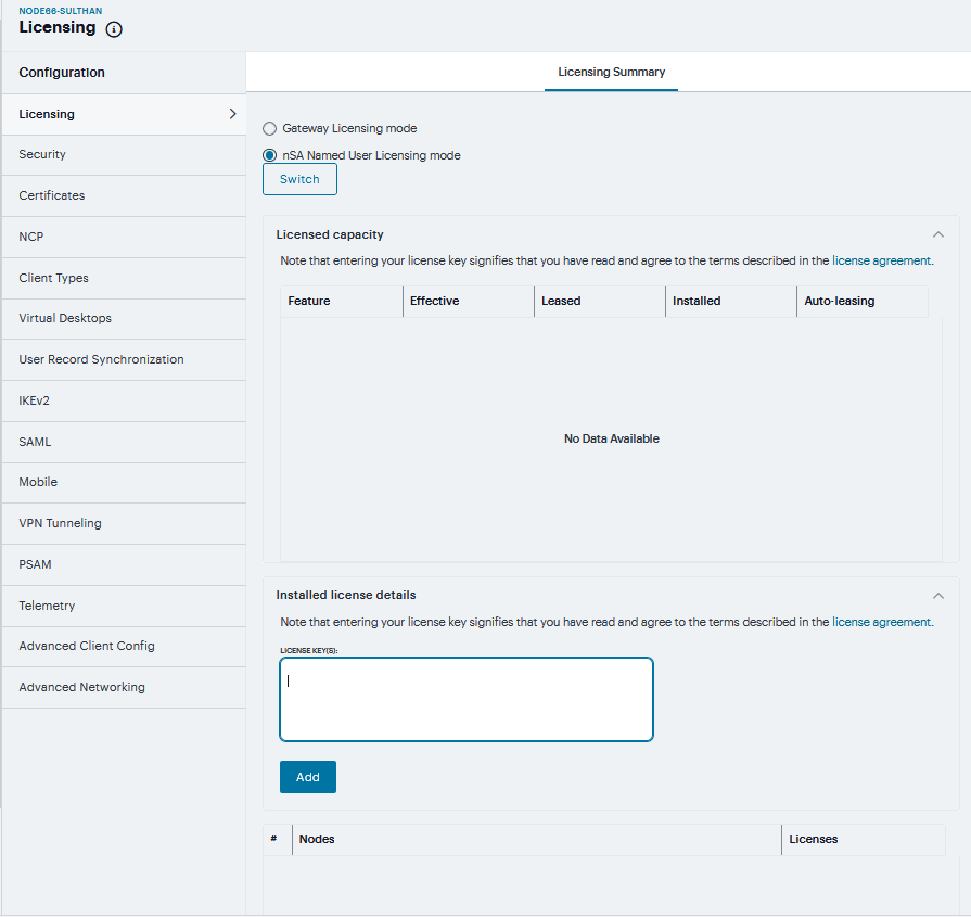
FIGURE 211 Licensing
Security Configuration
Granular cipher selection provides an administrator the ability to select specific ciphers and the preferred ordering of the selected ciphers. This feature also provides presets like Suite and PFS. There are two tabs, Inbound OpenSSL options and Outbound OpenSSL options. With this feature admins can select the ciphers that TLS/SSL connections will use. The Inbound OpenSSL options apply to all incoming connections. Outbound OpenSSL options apply to the following services:
Rewriter
ActiveSync
SCEP
Syslog
LDAPS
Inbound SSL Options
To enable the Inbound SSL options Mode:
Navigate to System > Configuration > Security > Inbound SSL Options.
Click on Turn on JITC mode check box.
Once Turn on JITC mode is enabled, Turn on NDcPP mode and Turn on FIPS mode are also automatically enabled.
In Inbound settings, select Allowed SSL and TLS Version and Allowed Encryption Strength.
Note
NDcPP mode can be enabled in the Inbound tab with a check box. This status is also applied over to the Outbound tab. Turning on NDcPP automatically turns on FIPS mode and disables SSL/TLS Version TLS1.0 and below. Also, NDcPP Mode allows to choose only 16 Ciphers under Custom Encryption Strength.
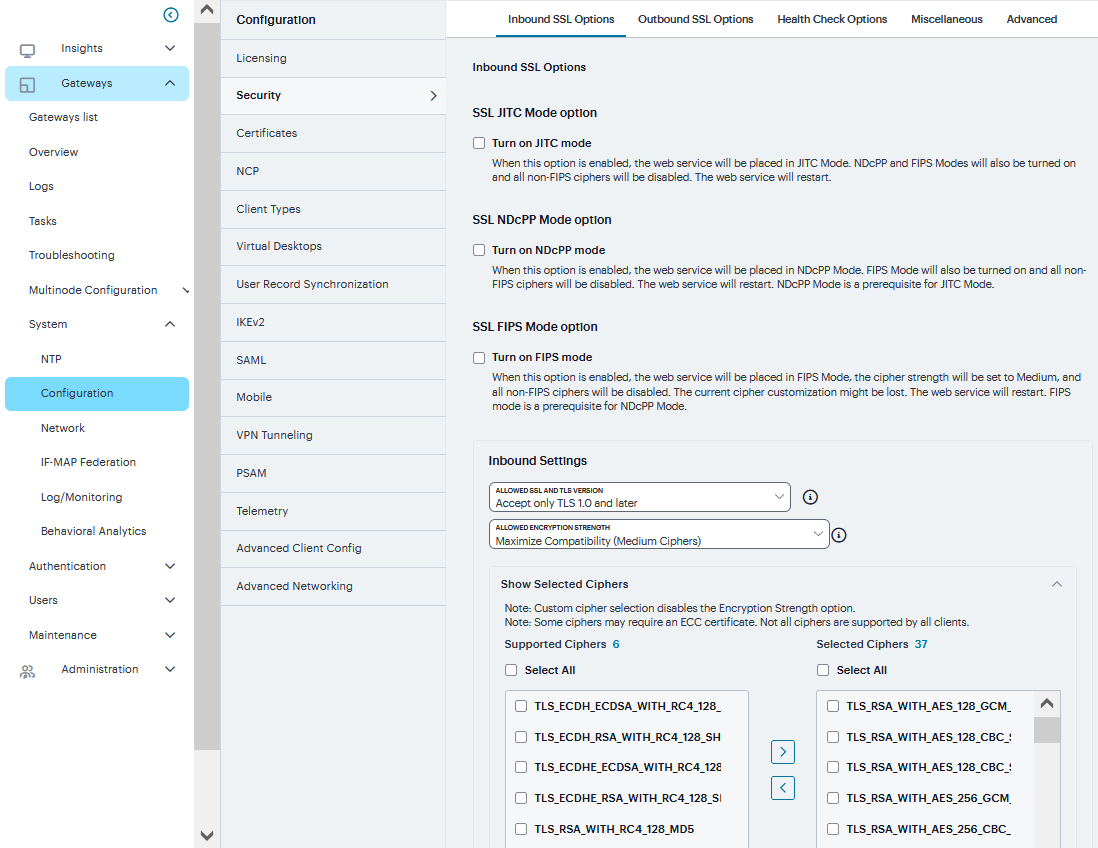
FIGURE 212 Inbound SSL Options
The two panels of Supported Ciphers and Selected Ciphers are displayed. Supported ciphers has the entire list of ciphers supported for the selected SSL or TLS version. Selected ciphers list the currently selected ciphers list.
Select Encryption Strength option to strengthen the SSL session that is established.
Select Key Exchange Options to increase the key exchange strength to 2048bit DHE.
Select Enable support for SSL legacy renegotiation to allow new TLS Renegotiation Info extension.
Set SSL Handshake Timeout option
Select Enable client certificate to enable Client certificate on the external port and/or the virtual ports.
The two panels of External Virtual Ports and Selected Virtual Ports are displayed. External Virtual Ports has the entire list of ports available for the selected certificate. Selected Virtual Ports list the currently selected ports list.
The two panels of Internal Virtual Ports and Selected Virtual Ports are displayed. Internal Virtual Ports has the entire list of ports available for the selected certificate. Selected Virtual Ports list the currently selected ports list. You can move the virtual ports from the external/internal to selected list and vice versa.
Click Save Changes.
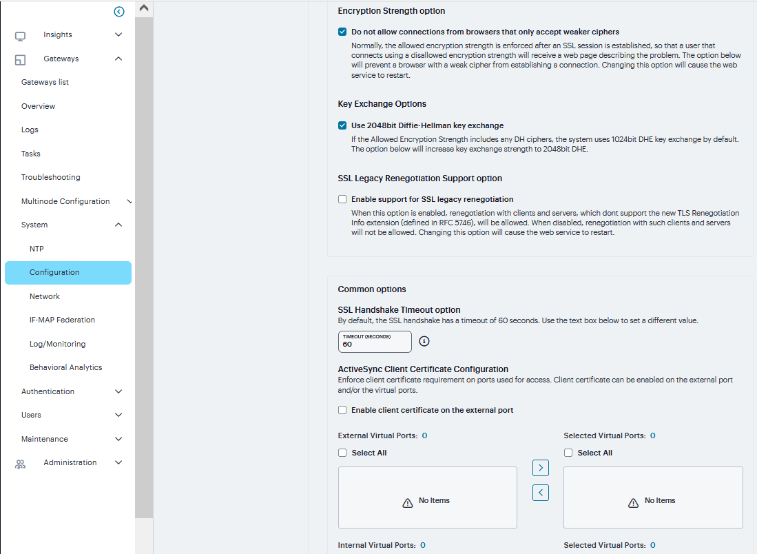
FIGURE 213 Inbound SSL Options
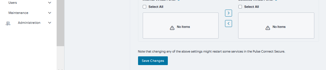
FIGURE 214 Inbound SSL Options
Outbound SSL Options
To enable the Outbound SSL options Mode:
Navigate to System > Configuration > Security > Outbound SSL Options.
Note
Only for Outbound SSL Settings, we can configure Non FIPS Ciphers when FIPS is Enabled using Custom Cipher Selection Option. Now, there are options to change different SSL/TLS versions and different encryptions in the Outbound SSL Settings.
DoD Certification Mode, SSL NDcPP Mode, and SSL FIPS Mode are OFF all these can be enabled from Inbound SSL options tab.
In Outbound settings, select Allowed SSL and TLS Version and Allowed Encryption Strength
The two panels of Supported Ciphers and Selected Ciphers are displayed. Supported ciphers has the entire list of ciphers supported for the selected SSL or TLS version. Selected ciphers list the currently selected ciphers list. The following figure shows the two panels (Supported Ciphers and Selected Ciphers). Note that the Selected Ciphers and Supported Ciphers List will also be displayed for all Preset like PFS or Suite B or Medium or High.
Click Save Changes.
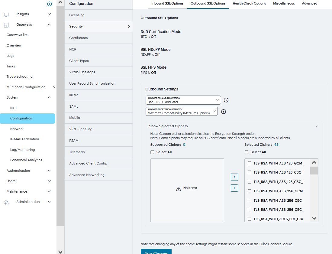
FIGURE 215 Outbound SSL Options
Health Check Options
To configure health check options:
Navigate to System > Configuration > Security > Health Check Options to display the configuration page.
Note
Enable additional information via healthcheck.cgi-This option is used by entities like load balancers to monitor the health status of the node.
Select the Enable additional information via healthcheck.cgi check box.
Click ‘+’ to add the relevant IPv4/v6 addresses for which additional information is required to be made available.
Click Save Changes.
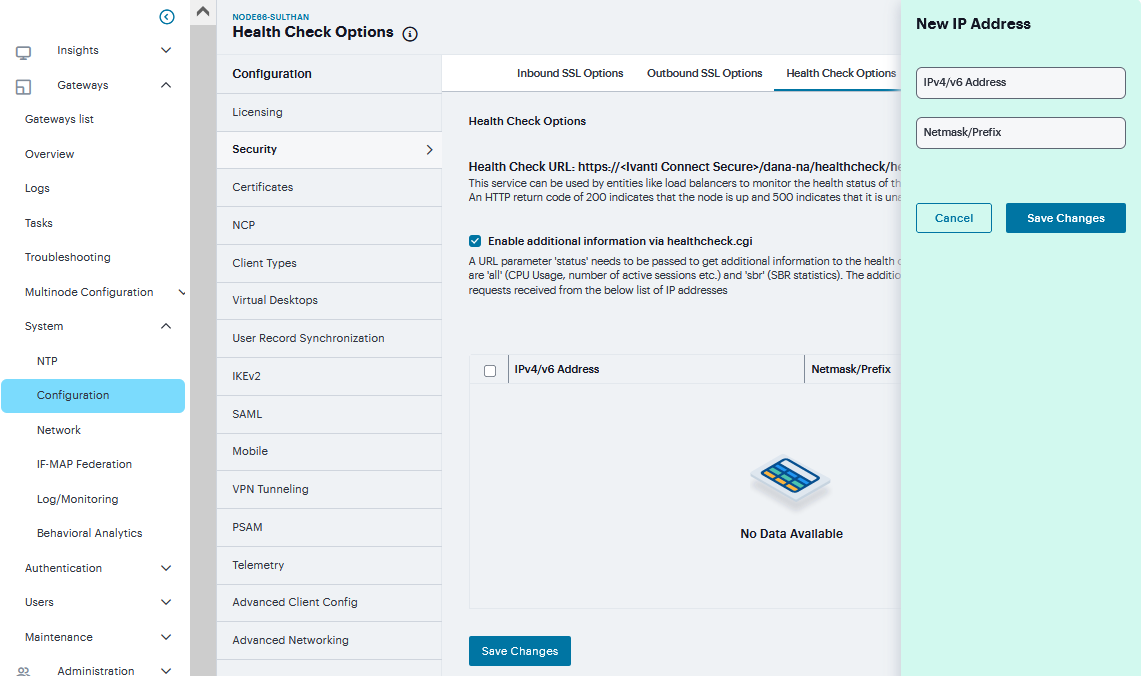
FIGURE 216 Health Check
Miscellaneous Setup
You can use the System > Configuration > Security > Miscellaneous page to configure the following security options:
Persistent cookie options - You can choose whether to preserve or delete persistent cookies when a session is terminated.
Lockout options - You can configure lockout options to protect the system from denial of service (DoS), distributed denial of service (DDoS), and password-guessing attacks.
Last login - You can choose whether to show users the time and IP address their user ID was used to sign in.
X-Frame-Options protection - You can choose to defend against click-jacking attacks by adding X-Frame-Option header to all the IVE generated pages. If this is not enabled, then only welcome.cgi will have this header.
Slow Post Attack Defense - You can configure to protect against slow-post DOS attacks from non-authenticated users.
HSTS - HTTP Strict Transport Security (HSTS) is a HTTP special response header which will prevent any communications over HTTP
Host Manifest Integrity Validation - You can configure to protect against integrity attacks.
Host Header Validation – You can block open redirect attacks
Username Validation – You can block unauthorized access
Integrity checking options - You can configure scan the system to periodically check for any integrity anomalies. If any anomaly found, information is displayed in the dashboard.
To configure cookie and lockout options:
Select System > Configuration > Security > Miscellaneous to display the configuration page.
Complete the configuration as described in the following table.
Click Save Changes.
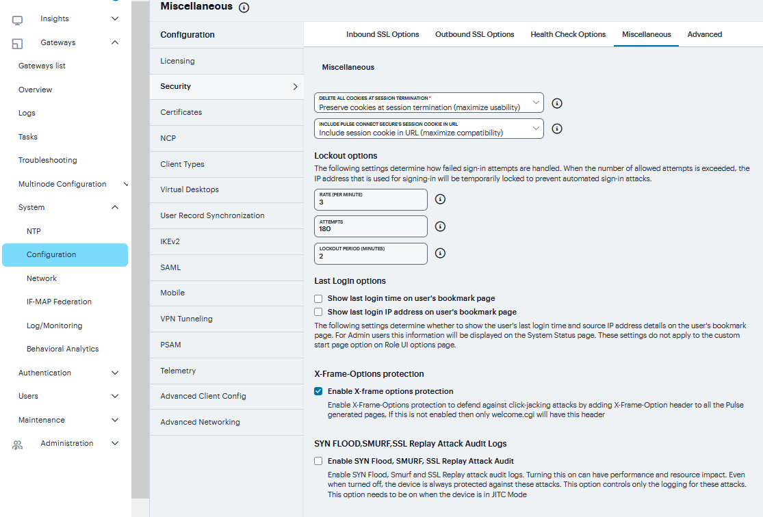
FIGURE 217 Miscellaneous
TABLE 5 Security Options Configuration Guidelines¶ Setting
Guidelines
Delete all cookies at session termination
Delete / Preserve
For convenience, the system sets persistent cookies on the user’s machine to support functions such as multiple sign-in, last associated realm, and the last sign-in URL. For additional security or privacy, you can choose not to set them.
Include Connect Secure’s session cookie in URL
Include / Not Include
Mozilla 1.6 and Safari may not pass cookies to the Java Virtual Machine, preventing users from running JSAM and Java applets. To support these browsers, the system can include the user session cookie in the URL that launches JSAM or a Java applet. By default, this option is enabled, but if you have concerns about exposing the cookie in the URL, you can disable this feature.
Lockout options
Rate
Specify the number of failed sign-in attempts to allow per minute.
Attempts
Specify the maximum number of failed sign-in attempts to allow before triggering the initial lockout. The system determines the maximum initial period of time (in minutes) to allow the failed sign-in attempts to occur by dividing the specified number of attempts by the rate. For ex-ample, 180 attempts divided by a rate of 3 results in an initial period of 60 minutes. If 180 or more failed sign-in attempts occur within 60 minutes or less, the system locks out the IP address being used for the failed sign-in attempt.
Lockout period
Specify the length of time (in minutes) the system must lock out the IP address.
Last Login options
Time / IP Address
Display the day and time and IP address the user last logged in to the system. For users, this information appears on their bookmark page. For administrators, this information appears on the System Status Overview page. These settings do not apply to the custom start page option on Role UI Options page.
X-Frame-Options protection
Enable X-Frame Options protection
By default, the Enable X-Frame-Options is checked. If the admin does not want to have this protection, they can uncheck this option. The X-Frame-Options HTTP response header can be used to indicate whether or not a browser should be allowed to render a page in a <frame>, <iframe> or <object>.
Slow Post Attack Defense
Timeout
By default, the POST body is received within 10 seconds. If the browser is unable to send the POST body within 10 seconds the connection is eventually dropped. (Configurable from 3 - 60Sec)
Maximum Request Size
By default, now a connection is directly rejected if it tries to POST more than 4KB in POST body (Configurable from 256 Bytes to 24 KB)
HSTS
Max Age
Specify the maximum age for HSTS. It can be disabled by configuring max age as 0.
Enable include Sub-domain directive
Select the check box to enable/disable the include Sub-domain directive. By default, it is turned off.
Enable preload directive
Select the check box to enable/disable the preload directive. By default, it is turned off.
Host Manifest Integrity Validation
Enable Host Manifest Integrity Validation to stop booting if manifest integrity validation fails
Select the check box to enforce host manifest integrity validation. By default, it is turned off. The following integrity checks are performed: Checks the SHA512 digital signature of the manifest file. Checks the SHA256 digest of each individual file entries in the manifest. If enabled and integrity check fails, admin needs to roll back to previous working package or perform factory reset.
Host Header Validation
Enable Host header validation to block open redirect attacks
Select the check box to enforce host header validation. By default, it is turned off. When Host header validation is enabled, every http request will be validated against hostnames and IP v4/v6 addresses known to the ICS server. If match is not found, the request will be dropped and logs are recorded in admin access logs and user access logs, and a response will be sent back to client.
Username Validation
Enable Username validation to block unauthorized access
Select the check box to enforce username validation for usage of unsupported characters. Max allowed length for username is 128 characters.
Runtime Integrity Scanner Interval
Periodic Scan
Select the time interval to run the integrity scanner during run time. For example: Select 2 hrs to run the integrity scanner every 2 hrs.
Scheduled Scan
Select to run integrity scanner at a specified time everyday. For example: When 13 hours 25 min is specified, the scanner runs at the same time everyday.
Referrer Header Validation
Enable Referrer Header validation to block CSRF attacks
Select the check box to enable referrer header validation.
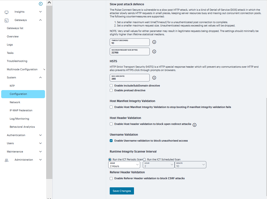
FIGURE 218 Miscellaneous
Advanced Configuration
Connect Secure supports several HTTP headers, which are sent in response to the client request. There are several more headers built to improve security and prevent attacks like XSS. The Custom HTTP Headers configuration enables the administrator to add new headers that they want to enforce.
To configure custom HTTP header:
Navigate to System > Configuration > Security > Advanced
Click ‘+’ to Add the relevant HTTP Header and Header Directive.
Click Save Changes
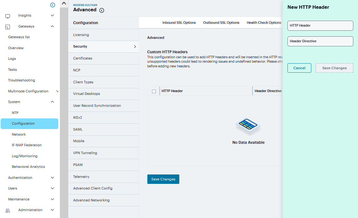
FIGURE 219 Advanced
Certificates
Connect Secure uses Public Key Infrastructure (PKI) to secure the data sent to clients over the Internet. PKI is a security method that uses public and private keys to encrypt and decrypt information. These keys are enabled and stored through digital certificates. A digital certificate is an encrypted electronic file issued by a certificate authority (CA) that establishes credentials for client/server transactions.
Device Certificates
A device certificate helps to secure network traffic to and from the Ivanti Secure Access client service using elements such as your company name, a copy of your company’s public key, the digital signature of the Certificate Authority (CA) that issued the certificate, a serial number, and an expiration date. When receiving the device certificate from the system, the client’s browser first verifies whether the device certificate is valid and whether the user trusts the CA that issued the certificate. If the user has not already indicated that they trust the certificate issuer, the Web browser prompts the user with a warning saying connection is untrusted or there is a problem with the websites security certificate.
To import an enterprise root server certificate and private key:
Select System > Configuration > Certificates > Device Certificates.
Click Import Certificate to display the configuration page.
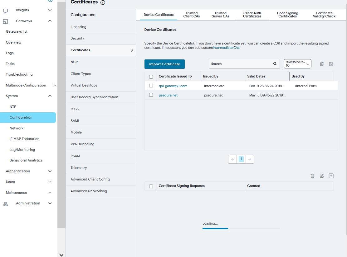
FIGURE 220 Device Certificates
Complete the configuration described in table.
Click Import.
Setting |
Guidelines |
|---|---|
If certificate and private file are separate keys |
|
Certificate File |
Browse to the network path or local directory location of your certificate key file. |
Private Key File |
Browse to the network path or local directory location of your private key file. |
Password Key |
Enter the password key. |
If certificate file includes private key |
|
Certificate File |
Browse to the network path or local directory location of the Certificate File. |
Password |
Enter the password. |
Import via System Configuration file |
|
System Configuration file |
Browse to the network path or local directory location of the Certificate File. With this option, the system imports all of the certificates specified (including private keys and pending CSRs, but not the corresponding port mappings). |
Password |
Enter the password. If the file is password-protected, enter the password key. |
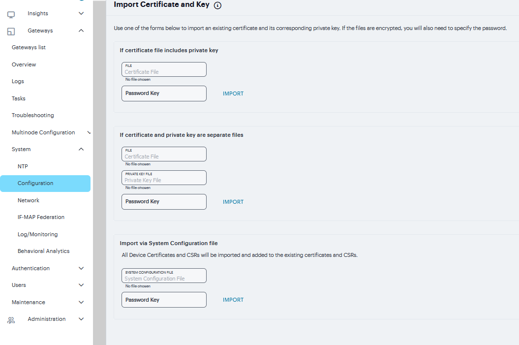
FIGURE 221 Import Certificate and Key
To create Certificate Signing Request (CSR) for RSA and ECC Keys:
Navigate to System > Configuration > Certificates > Client Auth Certificates.
Click ‘+’ on the Certificate Signing Requests pane.
Enter the required requestor information. In this example, the common name is ecc-p256.<orgname>.net or pcs.<orgname>.net.
If RSA is selected, then select Key Length and enter Random characters.
If ECC is selected, then select ECC Curve drop-down.
Click Save Changes.
The CSR is encoded and can be copied or saved to a file. The ECC certificate should be signed by an RSA/ECC CA for Suite B compliance. Follow your CA’s process for sending a CSR.
Click the Back to Device Certificates link. Until you import the signed certificate from your CA, your CSR is listed as Pending.
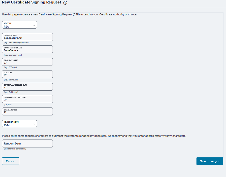
FIGURE 222 Certificate Signing Request
Trusted Client CAs
A trusted client CA is a CA that you deem trusted by adding it to the trusted client CA store. The system trusts any certificate issued by that CA. To use client CA certificates, you must install and enable the proper certificates. Additionally, you must install the corresponding client-side certificates in your users’ Web browsers, or you must use the MMC snap-in in your users’ computer accounts (machine certificate). When validating a client-side CA certificate, the system verifies that the certificate is not expired or corrupt and that the certificate is signed by a CA that the system has been configured to recognize. If the CA certificate is chained, the system also follows the chain of issuers until it reaches the root CA, validating each issuer in turn. The system supports X.509 CA certificates in DER and PEM encode formats.
To import a trusted client CA certificate:
Navigate to System > Configuration > Certificates > Trusted Client CAs to display the configuration page.
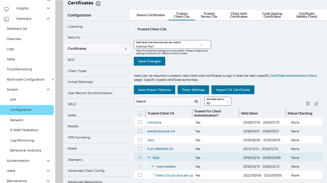
FIGURE 223 Trusted Client CAs
Click Import CA Certificate to display the configuration page.
Browse to the Certificate File, select it, and click Import to complete the import operation.
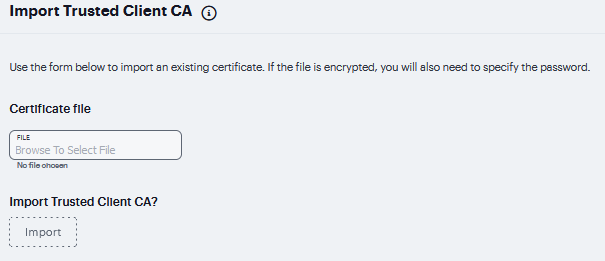
FIGURE 224 Certificate File
To enable auto-importing:
Navigate to System > Configuration > Certificates > Trusted Client CAs.
Click the Auto-Import Options button to display the options.
Complete the configuration described in the following table.
Click Save Changes.
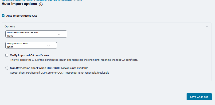
FIGURE 225 Auto-Import
Setting |
Guidelines |
|---|---|
Auto-import trusted CAs |
Select this option to enable auto-import and display its configuration settings. |
Client Certificate Status Checking |
|
CDP(s)/OCSP responder |
|
Verify imported CA certificates |
Select this option to verify that this trusted client CA is valid. Enabling this will check the CRL of this certificate’s issuer, and repeat up the chain until reaching the root trusted client CA. |
Skip Revocation check when OCSP/CDP server is not available |
|
To configure a proxy server:
Select System > Configuration > Certificates > Trusted Client CAs.
Click Proxy Settings to display the page.
Complete the configuration described in Proxy Settings table.
Click Save Changes.
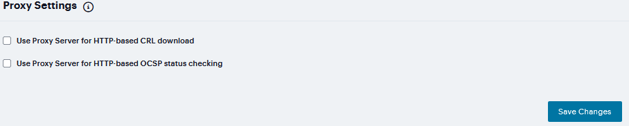
FIGURE 226 Proxy Settings
TABLE 8 Proxy Settings¶ Setting
Guidelines
Use Proxy Server for HTTP-based CRL download
Select to enable the CRL operations to use a proxy server. You can configure a proxy server for web-based URLs, not LDAP URLs.
Use Proxy Server for HTTP-based OCSP status checking
Select to enable the OCSP operations to use a proxy server.
Host Address
Specify either an IP address or a fully qualified domain name.
Port
Enter the proxy server port number if it is different from the default value of 80.
Username/password
If your proxy server required authentication, enter a username and password to log in to the proxy server.
Trusted Server CAs
All of the trusted root CAs for the Web certificates installed in Internet Explorer are preinstalled. You might need to install a trusted server CA for additional Web servers in the following situations:
If you are using third-party integrity measurement verifiers (IMVs) that are installed on a remote server, you must upload the trusted root certificate of the CA that signed the remote server’s server certificate.
If you are using virus signature version monitoring with your own staging site for storing the current virus signatures list, you must upload the trusted root certificate of the CA that signed the staging server certificate.
You can install the trusted root CA certificate on the endpoint in any of the following ways:
Use a CA certificate that is chained to a root certificate that is already installed on the endpoint, such as VeriSign.
Upload the CA certificate and any intermediate CA certificates to the Ivanti Secure Access client system. During client installation, the system automatically installs the trusted root device CA certificates on the endpoint. When prompted during installation, the user must allow the installation of the CA certificate(s).
Prompt users to import the CA certificates on the endpoint using Internet Explorer or other Microsoft Windows tools. In other words, you can use common methods organizations use to distribute root certificates.
To upload CA certificates:
Select System > Configuration > Certificates > Trusted Server CAs to display the page.
Click Import Trusted Server CA to display the page.
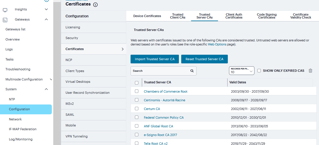
FIGURE 227 Trusted Server CAs
Browse to the Certificate File, select it, and click Import to complete the import operation.
FIGURE 228 Certificate File
To restore the prepopulated group of trusted CA certificates:
Select System > Configuration > Certificates > Trusted Server CAs.
Click Reset Trusted Server CAs.
Confirm that you want to restore the set of trusted server CAs that was installed when you upgraded.
Note
Connect Secure restores the group of pre-populated trusted server CAs that were installed upon upgrade. This operation clears all manually imported certificates.
Client Auth Certificates
In certain corporate environments, servers on the LAN are protected with two-way SSL authentication. These servers require the client to authenticate by presenting a valid certificate. In the remote access scenario, Ivanti Connect Secure is a client of these servers. You can configure Ivanti Connect Secure to present client authentication certificates to servers whenever it communicates over SSL. Note that Ivanti Connect Secure will present client certificates only when the SSL handshake requires it.
Note
This feature authenticates Ivanti Connect Secure (as a client) to back-end servers. It also authenticates end users or end-user machines to servers on the corporate LAN.
The access management framework allows certificates that include the private key and for instances where the private key is in a separate file from the certificate. In addition, if your certificates have been exported into a system configuration file, you can import the system configuration file to upload the certificates.
To import the client auth certificates files:
Select System > Configuration > Certificates > Client Auth Certificates.
Click Import Certificate to display the configuration page.
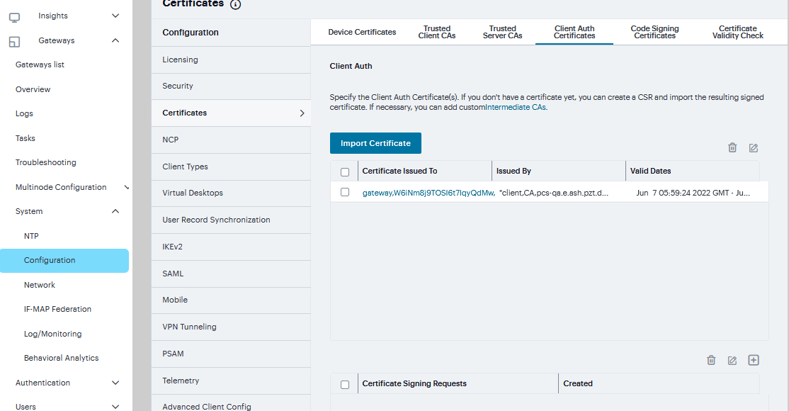
FIGURE 229 Client Auth Certificates
Complete the configuration described in table.
Click Import.
Setting |
Guidelines |
|---|---|
If certificate and private file are separate keys |
|
Certificate File |
Browse to the network path or local directory location of your certificate key file. |
Private Key File |
Browse to the network path or local directory location of your private key file. |
Password Key |
Enter the password key. |
Import via System Configuration file |
|
System Configuration File |
Browse to the network path or local directory location of the system configuration file. |
Password |
Enter the password. |
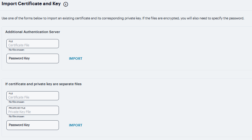
FIGURE 230 Import Certificate and Key Settings
To create Certificate Signing Request (CSR) for RSA and ECC Keys:
Navigate to System > Configuration > Certificates > Client Auth Certificates.
Click ‘+’ on the Certificate Signing Requests pane.
Enter the required requestor information. In this example, the common name is ecc-p256.<orgname>.net or pcs.<orgname>.net.
If RSA is selected then, select Key Length and enter Random characters.
If ECC is selected then, select ECC Curve drop down. Click Save Changes.
The CSR is encoded and can be copied or saved to a file. The ECC certificate should be signed by an RSA/ECC CA for Suite B compliance. Follow your CA’s process for sending a CSR.
Click the Back to Device Certificates link. Until you import the signed certificate from your CA, your CSR is listed as Pending.
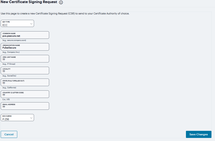
FIGURE 231 Certificate Signing Request
Code-Signing Certificates
In a basic setup, the only required certificates are a device certificate and a code-signing certificate. Ivanti Connect Secure can use a single code-signing certificate to resign all Java applets and a single device certificate to intermediate all other PKI-based interactions. If the basic certificates do not meet your needs, however, you may install multiple device and applet certificates on Ivanti Connect Secure or use trusted CA certificates to validate users.
When Ivanti Connect Secure intermediates a signed Java applet, it re-signs the applet with a self-signed certificate by default. This certificate is issued by a nonstandard trusted root CA. As a result, if a user requests a potentially high-risk applet (such as an applet that accesses network servers), the user’s Web browser alerts him that the root is untrusted.
To import a code-signing certificate:
Select System > Configuration > Certificates > Code-Signing Certificates to display the configuration page.
Click Import Certificates to display the configuration page.
Complete the configuration described in the following table.
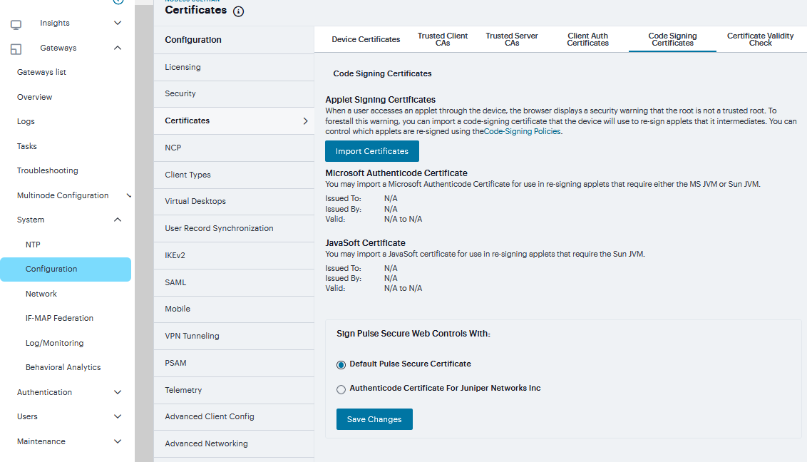
FIGURE 232 Code-Signing Certificates
The following table lists the Import Certificates Configuration Guidelines:
Setting |
Guidelines |
|---|---|
Microsoft Authenticode or Multipurpose Certificate for Internet Explorer (Microsoft JVM) |
|
Certificate File |
Browse to the network path or local directory location of your certificate key file. |
Private Key File |
Browse to the network path or local directory location of your private key file. |
Password Key |
Enter the password key. |
Javasoft Certificate for Internet Explorer & Netscape (Sun JVM) |
|
Keystore File |
Browse to the network path or local directory location of the keystore file. |
Password key |
Enter the password key. |
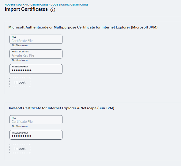
FIGURE 233 Import Certificates
Click Import to complete the import operation.
When you have successfully imported a certificate, the system displays the Sign Ivanti Web Controls With dialog box. Specify the signing option:
Default Ivanti Certificate - Select this option to sign all ActiveX and Java applets originating from Ivanti Connect Secure using the default Ivanti certificate. If you have previously selected an imported code-signing certificate and are reverting back to this option, after you click Save, a process icon appears indicating that the system is processing the request and re-signing all of the relevant code. This process can take several minutes to complete.
Authenticode Certificate - For <Imported Certificate Name>-Select this option to sign all ActiveX and Java applets using the certificate or certificates imported in the previous step. When you click Save, a process icon appears indicating that the system is processing the request and signing all of the relevant code. This process can take several minutes to complete.
Click Save Changes.
Certificate Validity Check
Every time a certificate is added to ICS (through manual import, XML import, or upgrade), its expiration date is stored in the cache. A background process checks all certification expiration dates once in every 7 days. If any certificate is about to expire soon, the administrator is notified. Notifications to administrators include a banner message in the adminUI upon login, SNMP trap, and log messages in the event log. The administrator can configure how soon he or she wishes to be notified of the expiration. The default is 60 days in advance. It can be configured to a value starting from 7 days in advance to 999 days in advance of the expiration of the certificate. The expiration warning window is common to all types of certificates. However, the administrator can choose to enable or disable this feature for each certificate category in the user interface.
To check validity of certificates:
Click on Configuration > Certificates > Certificates Validity Check.
The page displays the Certificate Expiry Notification Duration and the Certificate Types.
Enter the number of days before which the warning must be displayed.
Select the type of certificate for which the expiry notification is required. By default, all types of certificates will be selected if no selection is made.
Click on Check Now. The Certificate Category, DN name and date of expiry are displayed.
When an administrator logs in, a warning sign is displayed, if there are any certificates that expire within the configured number of days.

FIGURE 234 Certificates Validity Check
NCP Configuration
The following types of internal protocols are used to communicate between Ivanti Connect Secure and client applications:
Network Communications Protocol (NCP) - Standard NCP has been replaced with oNCP. Windows client applications, PSAM, and Terminal Services fallback to NCP if oNCP fails.
Optimized NCP (oNCP) - oNCP significantly improves the throughput performance of the client applications over NCP because it contains improvements to protocol efficiency, connection handling, and data compression. Windows client applications, PSAM, and Terminal Services use oNCP by default.
Java Communications Protocol (JCP) -JCP is the Java implementation of standard NCP. The system uses JCP to communicate with Java client applications, JSAM, and the Java Content Intermediation Engine.
To set NCP options:
Navigate to System > Configuration > NCP.
(Windows clients) Under NCP Auto-Select, select:
Auto-select Enabled (recommended) - Use the oNCP by default. If you select this option, the system uses oNCP for most client/server communications and then switches to standard NCP when necessary. The system reverts to NCP if the user is running an unsupported operating system, browser type, or combination thereof, or if the client application fails to open a direct TCP connection to the device for any reason (for instance, the presence of a proxy, timeout, disconnect).
Auto-select Disabled - Always use standard NCP. This option is primarily provided for backwards compatibility.
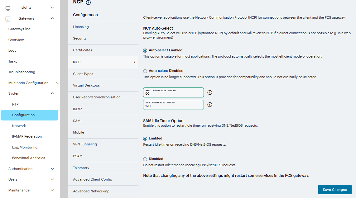
FIGURE 235 NCP
Note
If you are using Network Connect to provide client access, we recommend that you exercise caution when employing the Auto-select Disabled option, as Mac and Linux clients cannot connect using the traditional NCP protocol. If you disable the oNCP/NCP auto-selection feature and a UDP-to oNCP/NCP fail-over occurs, the system disconnects Macintosh and Linux clients because it fails over from UDP to NCP (instead of oNCP), which does not support these users.
(Java clients) Under Read Connection Timeout, set the timeout interval for Java clients (15-120 seconds). If client-side secure access methods do not receive data from the system for the specified interval, they try to reestablish a connection. Note that this value does not apply to user inactivity in client applications.
(Windows clients) Under Idle Connection Timeout, set the idle connection interval. This timeout interval determines how long the system maintains idle connections for client-side Windows secure access methods.
Under SAM Idle Timer enable/disable idle timer to receive DNS/NetBIOS requests
Click Save Changes.
Client Types Configuration
The Client Types tab allows you to specify the types of systems your users may sign in from and the type of HTML pages to display when they do. In addition, client types are used to identify the operating system shown on the Device Management page for devices that use ActiveSync to synchronize e-mail with a Microsoft Exchange server. The user agent string used to identify a device during login may be different from the one in the ActiveSync message. For example, in the list of default user agent strings, Apple-iPhone and Apple-iPad are used only in ActiveSync messages.
To manage the client types:
Navigate to System > Configuration > Client Types.
In the User-agent string pattern text box, enter the user agent string for the operating system (s) that you want to support. You can specify all or part of the string. For example, you can use the default DoCoMo string to apply to all DoCoMo operating systems, or you can create a string such as DoCoMo/1.0/P502i/c10 to apply to a single type of DoCoMo operating system. You can use the * and ? wildcard characters in the string. Note that user agent strings on the system are case-insensitive.
Select the type of HTML to display to users who sign in from the operating system specified in the previous step. Options include:
Standard HTML - The system displays all standard HTML functions, including tables, full- size graphics, ActiveX components, JavaScript, Java, frames, and cookies. Ideal for standard browsers, such as Firefox, Mozilla, and Internet Explorer.
Compact HTML (iMode) - The system displays small-screen HTML-compatible pages. This mode does not support cookies or the rendering of tables, graphics, ActiveX components, JavaScript, Java, VB script, or frames. (The only difference between this option and the Smart Phone HTML Basic option is the user interface.) Ideal for iMode browsers.
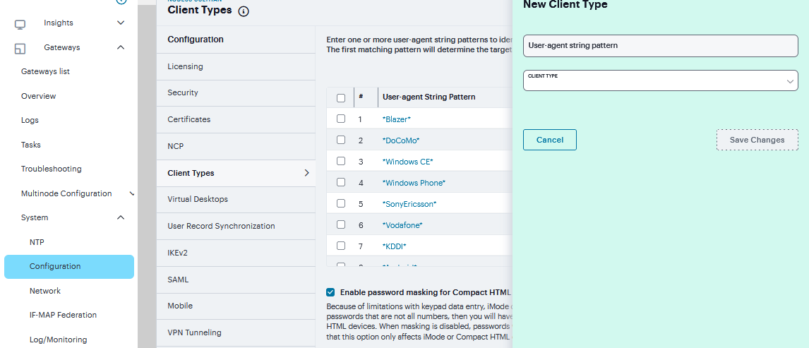
FIGURE 236 Client Types
Note
Form Post SSO is not supported on iMode appliances.
Mobile HTML (Pocket PC) - The system displays small-screen HTML-compatible pages that may contain tables, small graphics, JavaScript, frames, and cookies, but this mode does not facilitate the rendering of java applets or ActiveX components. Ideal for Pocket PC browsers.
Smart Phone HTML Advanced - The system displays small-screen HTML-compatible pages that may contain tables, small graphics, frames, cookies, and some JavaScript, but this mode does not facilitate the rendering of java applets, ActiveX components, or VB scripts. Ideal for Treo and Blazer browsers.
Smart Phone HTML Basic - The system displays small-screen HTML-compatible pages. This mode does not support cookies or the rendering of tables, graphics, ActiveX components, JavaScript, Java, VB script, or frames. (The only difference between this option and the Compact HTML option is the user interface.) Ideal for Opera browsers on Symbian.
Note
The system rewrites hyperlinks to include the session ID in the URL instead of using cookies.
Mobile Safari, Android, Symbian, iPad - The Mobile Safari (iPhone/iPod Touch), Android, and Symbian selections have Basic, Advanced, and Full HTML options.
Specify the order that you want to evaluate the user agents. The system applies the first rule in the list that matches the user’s system. For example, you may create the following user agent string/HTML type mappings in the following order
User Agent String: DoCoMo Maps to: Compact HTML
User Agent String: DoCoMo/1.0/P502i/c10 Maps to: Mobile HTML
If a user signs in from the operating system specified in the second line, the system will display compact HTML pages to him, not the more robust mobile HTML, since his user agent string matches the first item in the list. To order mappings in the list, select the check box next to an item and then use the up and down arrows to move it to the correct place in the list.
Select the Enable password masking for Compact HTML check box if you want to mask passwords entered in iMode and other devices that use compact HTML. (Devices that do not use compact HTML mask passwords regardless of whether or not you select this check box.) Note that if your iMode users’ passwords contain non-numeric characters, you must disable password masking because iMode devices only allow numeric data in standard password fields. If you disable masking, passwords are still transmitted securely, but are not concealed on the user’s display.
Click Save Changes.
Virtual Desktops Configuration
In addition to standard resource profiles and resource profile templates, you can configure virtual desktops as resource profiles. As with the other resource profiles, a virtual desktop profile contains all of the role assignments and end-user bookmarks required to provide access to an individual resource. Unlike other resource profile types, there is no resource policy to configure for virtual desktops due to the dynamic nature of virtual desktops. The IP address and port of the system is not known until the end user launches a session so dynamic ACLs are used.
You can use the Virtual Desktop Configuration page to define the client delivery mechanism for end-users who do not have the client. The process is similar for both Citrix XenDesktop and VMware View Manager.
Navigate to System > Configuration > Virtual Desktops.
For View Client Delivery Method Select VMware.
For Citrix XenDesktop, select Citrix.
Select Download from Ivanti Connect Secure to download the client file from the system. Click File to locate the client file (.msi, .exe or .cab) and enter the version number.
Select Download from a URL to download the client file from the Internet. If desired, enter a new URL to override the default.
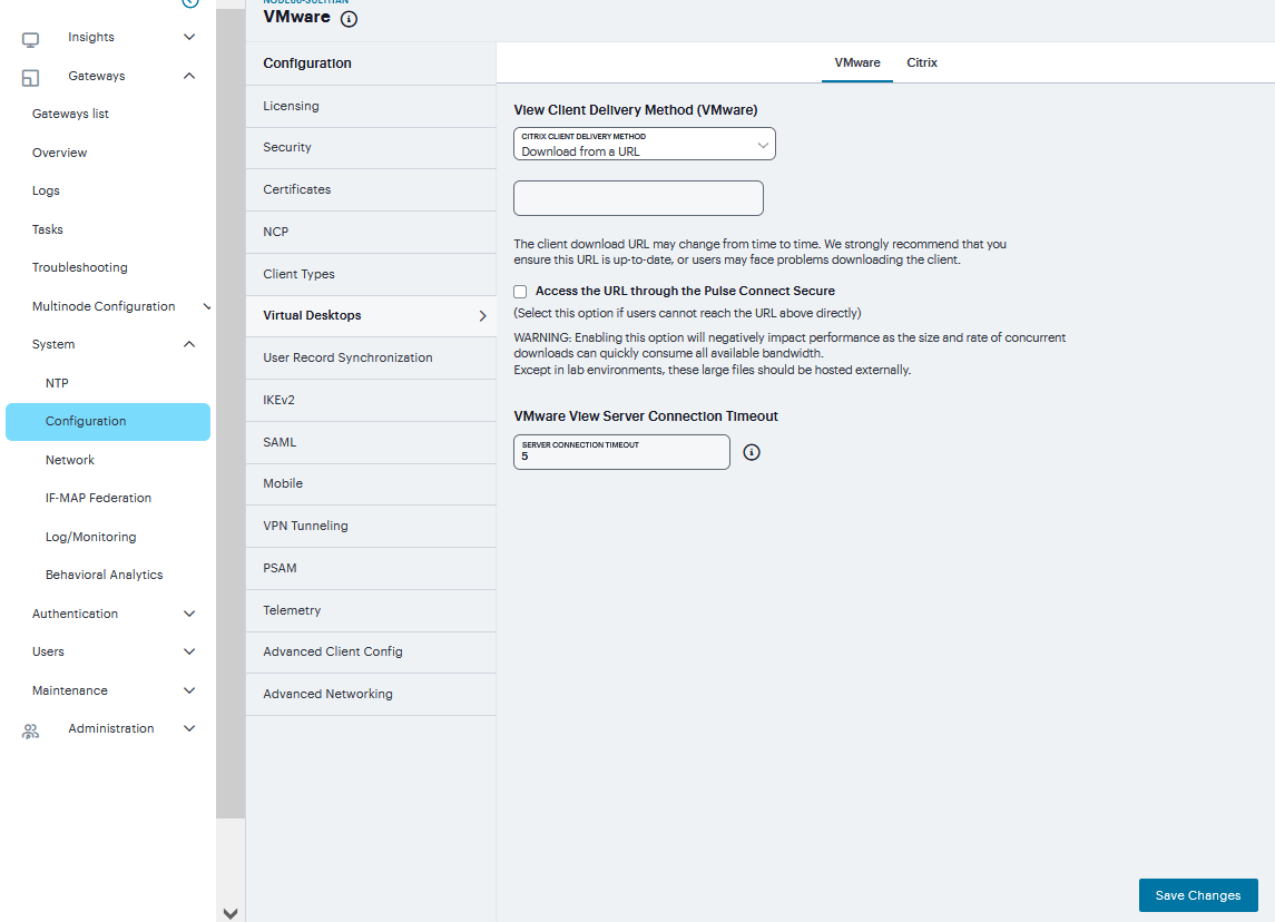
FIGURE 237 Virtual Desktops
Check the Access the URL through the Ivanti Connect Secure check box if end users cannot directly access the specified Web page. Selecting this option allows users to use the secure gateway to access the URL.
Under Server Connection Timeout, enter the number of seconds to wait for the server to respond before timing out.
User Record Synchronization
The user record synchronization feature promotes a more consistent user experience by allowing users to retain their bookmarks and individual preferences regardless of which device they log in to.
User record synchronization relies on client-server pairings. The client is the device that users log in to start their remote access. Each client is associated with one primary server and one backup server to store user record data. Clients can be individual appliances or a node within a cluster.
A server in this instance is the device that stores the user data records. Each server can be configured to replicate its user record data to one or more peer servers. Servers are identified by a user-defined logical name. The same logical name can be assigned to more than one authentication server to let you associate authentication servers of different types to the same user. For example, SA1 is an ACE authentication server with user1 who creates a bookmark to www.<orgname>.net. SA2 is an Active Directory authentication server with the same user1. For the www.<orgname>.net bookmark to be transferred from SA1/ACE/user1 to SA2/AD/user1 you would assign the logical name “Logical1” to both the ACE server on SA1 and the Active Directory server on SA2.
General Setup
Navigate to System > Configuration > User Record Synchronization > General.
Select the Enable User Record Synchronization check box.
Enter a unique node name. This name is used when associating a client with a server and is different from the logical name assigned to a server. This node name is also not the same as the cluster node name.
Enter the shared secret and confirm it. The shared secret is the password used to authenticate the client with its servers and the primary server with its peer servers. Use the same shared secret for all clients and servers participating in user record synchronization.
Select whether this node is client only or if this node acts as both a client and server.
Click Save Changes.
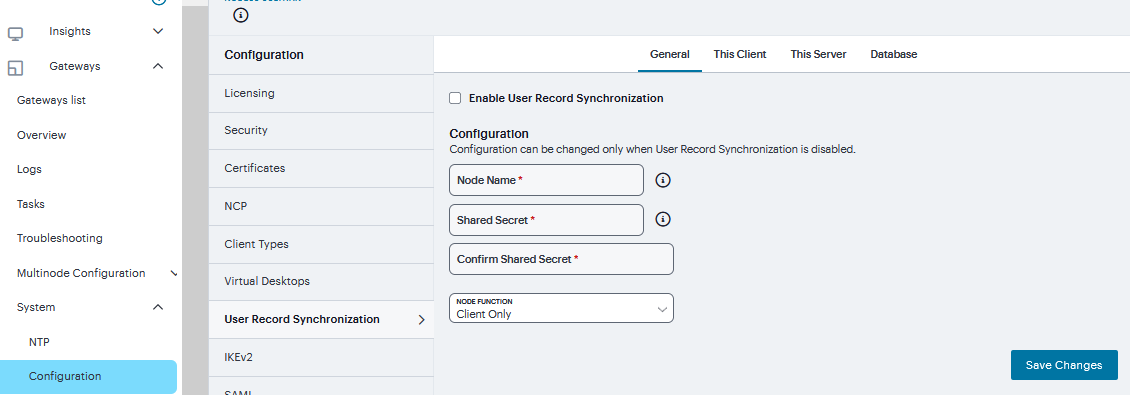
FIGURE 238 General
Note
If you need to make any changes in this window at a later time, you must deselect the Enable User Record Synchronization check box and click Save Changes. Make your edits, select the Enable User Record Synchronization check box and save your changes.
Once you enter a name and shared secret, you cannot clear these fields.
Client Configuration
To set up the client, you select the primary and backup server you want this client to synchronize with:
Navigate to System > Configuration > User Record Synchronization > This Client.
Click ‘+’, Select the LAS name you want to synchronize and enter the primary IP of the user record. If you prefer to synchronize with any available server, select Any LAS.
Enter the Primary and optionally a Backup server’s IP address and then click Save Changes.
Even if you select Any LAS, you must enter a primary server IP address. Once added, the primary and backup servers have a colored icon next to their name indicating their connection status.
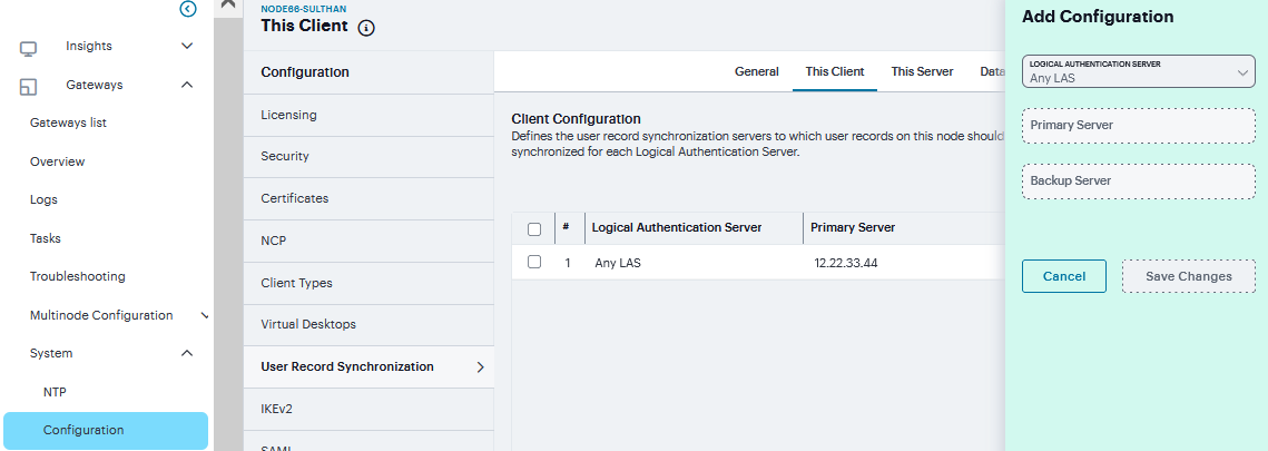
FIGURE 239 Client
Server Configuration
To set up the user record synchronization server you must define its peer nodes (optional) and the clients that can access this server.
Navigate to System > Configuration > User Record Synchronization > This Server.
Under Peer Server, click ‘+’and enter the peer server’s Node name and IP address, then click Save Changes. To specify more than one peer server, enter each server’s node name and IP address individually and click Save Changes. There is no limit on the number of peer servers you can add.
Data is replicated from the primary or backup server to its peer servers. If the primary is not available, user data is sent to the backup. User data is then replicated to the peer servers.
For each client you want synchronized with this server, Under Client Nodes, click ‘+’enter the Client’s name and IP address and click Save Changes.
Once added, peer servers will have a colored icon next to their name indicating their connection status. Node status is provided to client nodes and LAS mapping servers as well.
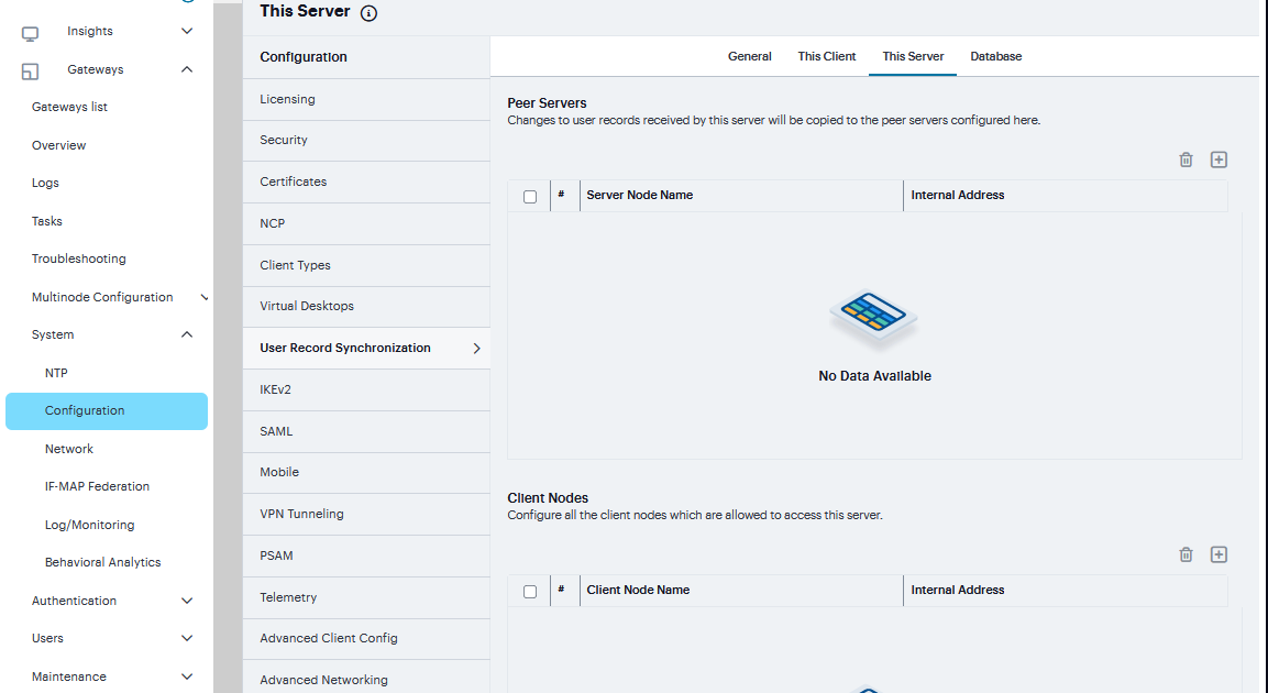
FIGURE 240 Server
Database Configuration
With the Database tab, you can delete inactive records from the client cache, retrieve statistics about the database, export and import the data and remove user data from the server’s database.
To configure the database:
Navigate to System > Configuration > User Record Synchronization > Database.
Select Auto-delete inactive synchronized user records from the Cache to remove inactive user records from the cache and not from the user record database.
When this option is selected, the system performs a check every 15 minutes and deletes user records that meet all of the following criteria:
There are no active user sessions associated with the user record.
The user record does not have any custom settings, or the latest version of the user record has been synchronized with the user record database.
The authentication server associated with the user record database does not have type “local”. For example, the “System Local” auth server that is part of the default configuration of the system has a “local” type, so any user records associated with that auth server will not be auto-deleted. However, user records associated with external authentication servers like Radius or LDAP may be deleted, depending on the two prior criteria.
Click Save Changes.
Under Export, you export user records to a file. The user records can be exported from the user record database, or from the cache. The exported file can be used to pre-populate the user record database on another node.
To encrypt the exported data, select the Encrypt the exported data with password check box and enter the Password and Confirm it.
Click Export to export the user records from the specified source (cache or database). You will be prompted where to save the file.
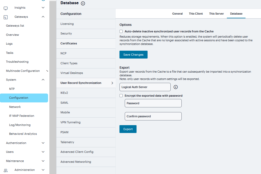
FIGURE 241 Database
IKEv2 Configuration
IKE or IKEv2 (Internet Key Exchange) is the protocol used to set up a security association in the IPsec protocol suite. Microsoft Windows 7 fully supports the IKEv2 standard through Microsoft’s Agile VPN functionality and can operate with a VPN gateway using these protocols. Information on IKE and IKEv2 is widely available on the Internet. It is not the intent of this guide to describe details about IKE and IKEv2.
The system supports IKEv2, enabling interoperability with clients or devices, such as smartphones, that have a standards-based IPSec VPN client. IKEv2 clients count toward the total number of sessions. Thus, the total number of sessions = number of IKEv2 sessions + number of NCP sessions. The system supports the following methods for authenticating IKEv2 clients:
Machine certificate-based authentication
Authentication using EAP methods
Note
IKEv2 uses port 500 exclusively. Do not configure port 500 in your VPN Tunneling profiles.
To configure the IKEv2 ports and EAP protocol:
Navigate to System > Configuration > IKEv2 to display the configuration page.
Enter the DPD timeout value in seconds. Valid values are 400-3600.
DPD is a form of keepalive. When a tunnel is established but idle, one or both sides may send a “hello” message and the other replies with an acknowledgement. If no response is received, this continues until the DPD time value has elapsed. If there still is no traffic or acknowledgement, the peer is determined to be dead and the tunnel is closed.
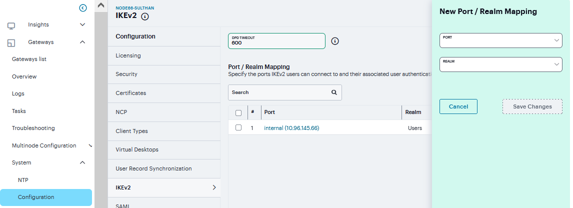
FIGURE 242 Port/Realm Mapping
Under Port/Realm Mapping, click ‘+’ select the Port and the Realm to use that port and click Save Changes.
Under Realm/Protocol Set Mapping, click ‘+” select the Realm and the EAP protocol set to use for that realm.
The three Protocol Set Options include EAP-MSCHAP-V2, EAP-MD5-Challenge, and EAP-TLS.
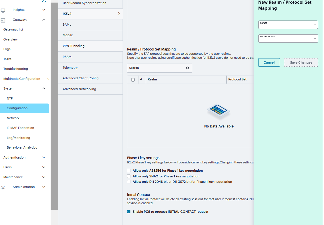
FIGURE 243 Realm/Protocol Set Mapping
To Configure Phase-1 Key Settings, select the required Phase 1 Key Settings.
Three new UI options are available to enforce:
Encryption Algorithm (AES256)
Integrity Algorithm (SHA256, SHA384 and SHA512)
Diffie-Hellman Group (DH 2048 and DH3072).
Enabling these options mean more secured Phase 2 negotiations. When AES256 is enabled, AES256 Encryption Algorithm is preferred over AES128 or 3DES. When SHA2 is Enabled, SHA2 Integrity Algorithm is preferred over SHA1 and When DH is Enabled, DH2048 or DH3072 Diffie-Hellman Group is preferred over DH1024.
Click Save Changes.
Note
Changing IKEv2 configuration (System > Configuration > IKEv2) disconnects connections from IKEv2 clients, VPN Tunneling and Ivanti. VPN Tunneling and Ivanti will reconnect automatically.
SAML Configuration
SAML is an XML-based framework for communicating user authentication, entitlement, and attribute information. The standard defines the XML-based assertions, protocols, bindings, and profiles used in communication between SAML entities. SAML is used primarily to implement Web browser single sign-on (SSO). SAML enables businesses to leverage an identity-based security system like Ivanti Connect Secure to enforce secure access to web sites and other resources without prompting the user with more than one authentication challenge.
You use the System > Configuration > SAML pages to maintain a table of SAML metadata files for the SAML service providers and identity providers in your network. Using SAML metadata files makes configuration easier and less prone to error. You can add the metadata files to the system by:
Uploading a metadata file.
Retrieving the metadata file from a well-known URL.
To add metadata files:
Navigate to System > Configuration > SAML.
Click ‘+’’ to display the configuration page.
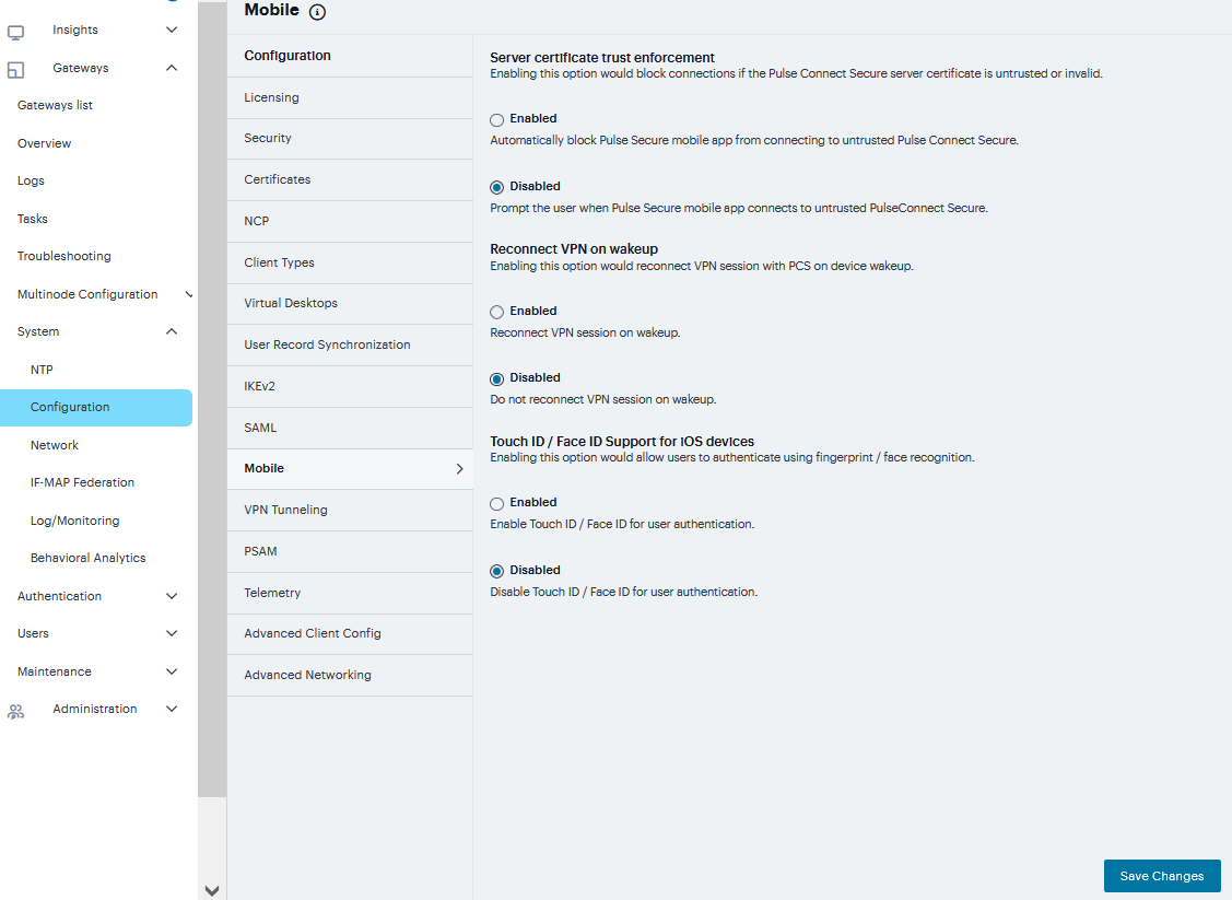
FIGURE 244 SAML
Enter New Metadata Provider name.
Complete the settings described in the following table
Click Save Changes
TABLE 11 SAML Metadata Provider Configuration Guidelines¶ Setting
Guidelines
Metadata Provider Location Configuration
Select one of the following methods:
Local Browse and locate the metadata file on your local host or file system.
Remote Enter the URL of the metadata file. Only http and https protocols are supported.
Upload Metadata File
You can upload the metadata file directly.
Metadata Provider Verification Configuration
Accept Unsigned Metadata
If this option is not selected, unsigned metadata is not imported. Signed metadata is imported only after signature verification.
Signing Certificate
Browse and locate the certificate that verifies the signature in the metadata file. This certificate overrides the certificate specified in the signature of the received metadata. If no certificate is uploaded here, then the certificate present in the signature of the received metadata is used.
Select the Enable Certificate Status Checking option to verify the certificate before using it. Certificate verification applies both to the certificate specified here and the certificate specified in the signature in the metadata file.
Metadata Provider Filter Configuration
Roles
Select whether the metadata file includes configuration details for a SAML service provider, identity provider, or Policy Decision Point. You may select more than one. If you select a role that is not in the metadata file, it is ignored. If none of the selected roles are present in the metadata file, the system returns an error.
Entity IDs To Import
Enter the SAML Entity IDs to import from the metadata files. Enter only one ID per line. Leave this field blank to import all IDs. This option is available only for uploading local metadata files.
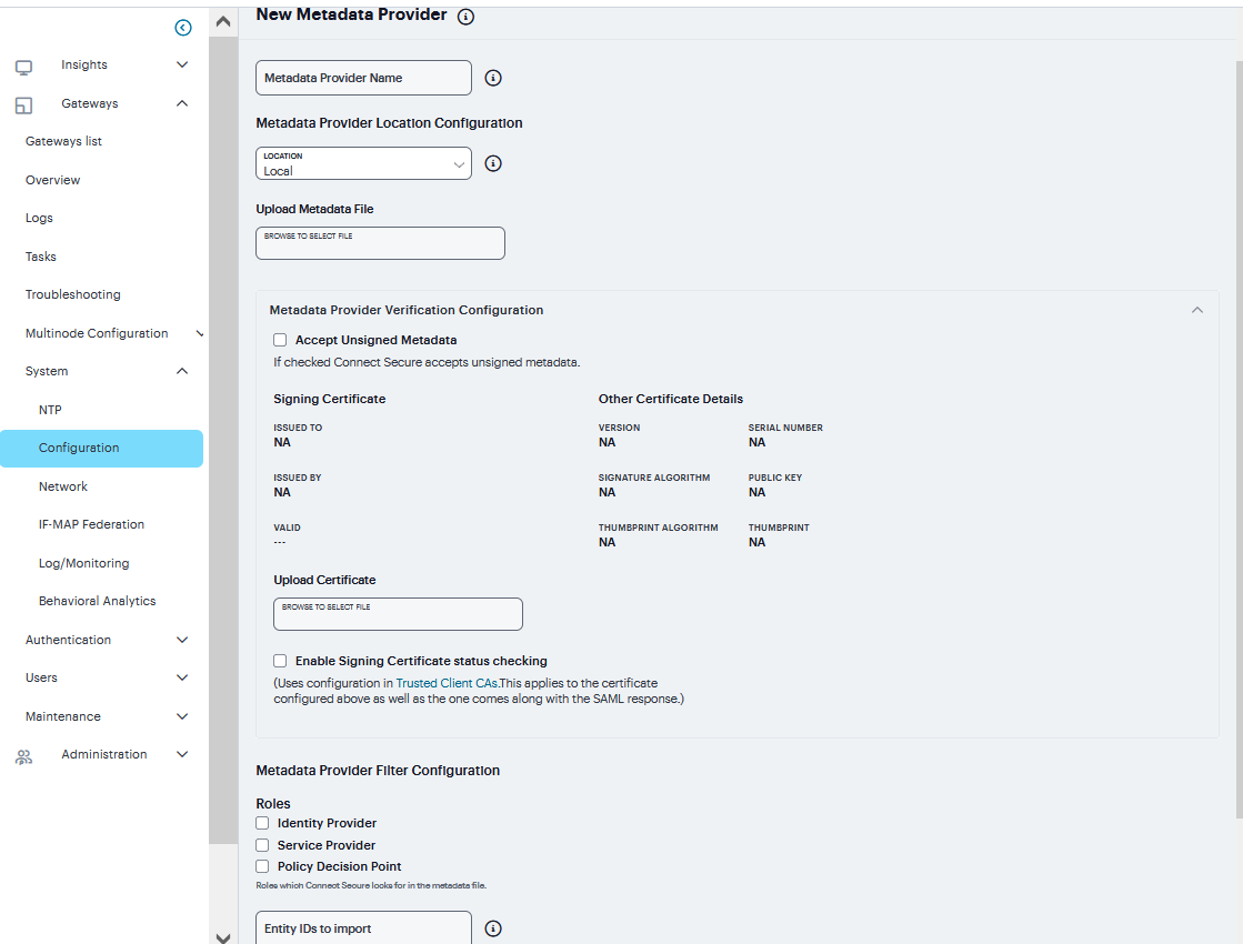
FIGURE 245 SAML Metadata Provider
Mobile Configuration
This topic describes the mobile options that are available on Ivanti Connect Secure. To configure the mobile option, go to System > Configuration > Mobile. It includes the following information:
Setting |
Guidelines |
|---|---|
Server certificate trust enforcement |
Enables you to block connections if the Ivanti Connect Secure server certificate is untrusted or invalid. When enabled, it automatically blocks the Ivanti mobile app from connecting to untrusted Ivanti Connect Secure. When disabled, it prompts when a Ivanti mobile app connects to untrusted Ivanti Connect Secure. |
Reconnect VPN on wakeup |
Enables you to reconnect a VPN session with ICS on device wakeup. |
Touch ID / Face ID Sup-port for iOS devices |
Enables you to authenticate using fingerprint / face recognition. |
FIGURE 246 Mobile
VPN Tunneling Configuration
The VPN tunneling access option (formerly called Network Connect) provides a VPN user experience, serving as an additional remote access mechanism to corporate resources using Connect Secure. This feature supports all Internet-access modes, including dial-up, broadband, and LAN scenarios, from their client machine and works through client-side proxies and firewalls that allow SSL traffic.
When a user launches VPN tunneling, the system transmits all traffic to and from the client over the secure VPN tunnel. The only exception is for traffic initiated by other system-enabled features, such as Web browsing, file browsing. If you do not want to enable other system features for certain users, create a user role for which only the VPN tunneling option is enabled and make sure that users mapped to this role are not also mapped to other roles that enable other system features.
To configure VPN tunneling:
Navigate to System > Configuration > VPN Tunneling.
Under Access Control List (ACL) Count Enforcement enable to block VPN tunneling sessions when the total number of ACL rules exceeds 60,000.
Under IPv6 ESP Settings, enter UDP Port number and select the Use ESP tunnel for 6in4 and 4in6 traffic check box.
Under Precedence of FQDN / IP section, check Prefer FQDN resources over IP resources in case of a split tunneling conflict.
Under Enable/Disable FQDN ACL, check to Enable FQDN ACL
Click Save Changes.
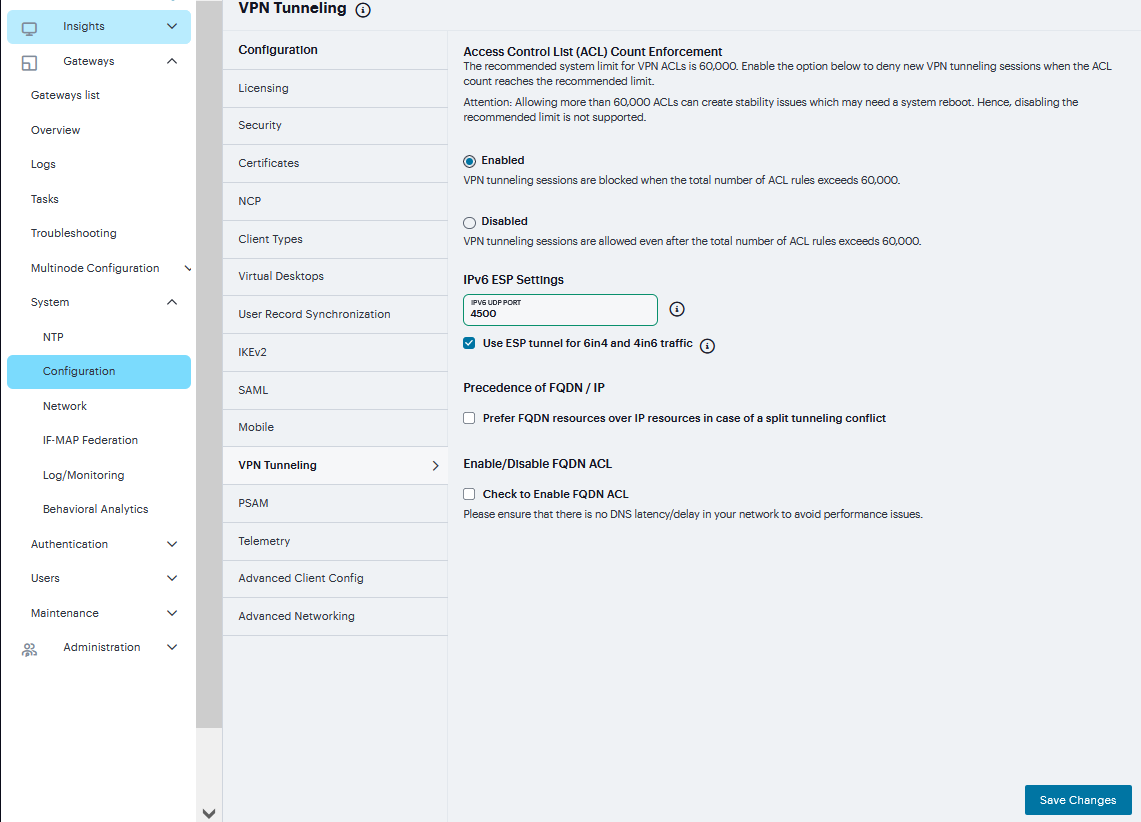
FIGURE 247 VPN Tunneling
PSAM Configuration
The Secure Application Manager option provides secure, application-level remote access to enterprise servers from client applications. The Windows version of the Secure Application Manager is a Windows-based solution that enables you to secure traffic to individual client/server applications and application servers.
To Configure PSAM:
Navigate to System > Configuration > PSAM
Under Precedence of FQDN / IP section, check Prefer FQDN resources over IP resources in case of a resource ACL conflict.
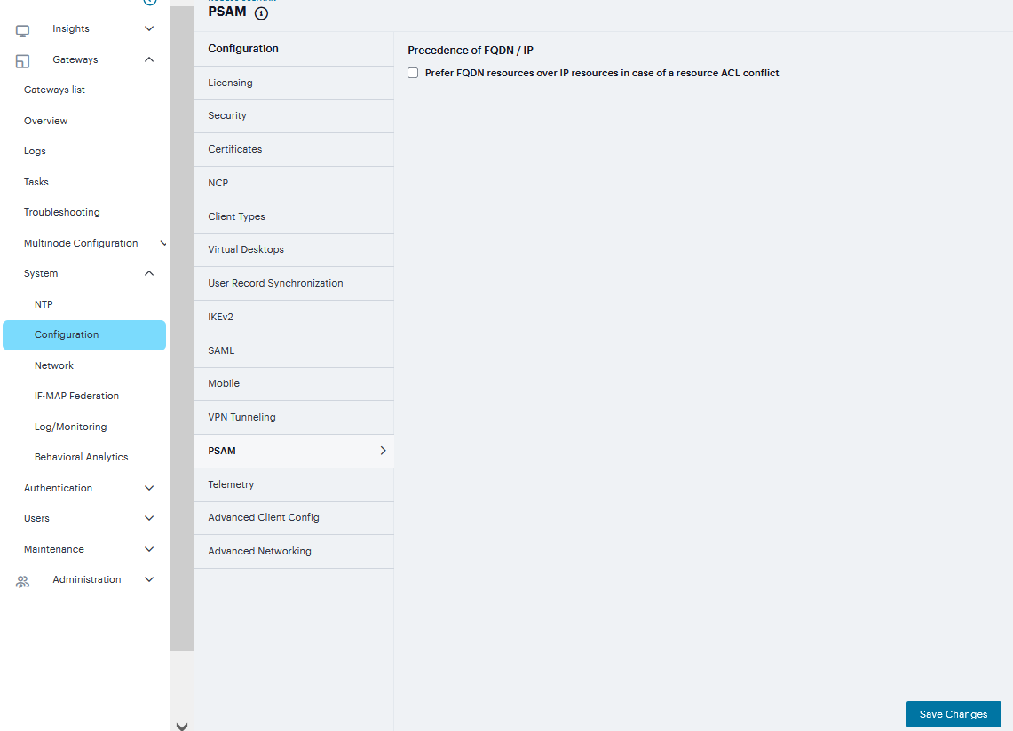
FIGURE 248 PSAM
Telemetry Settings
Telemetry Settings helps you to enable Google Analytics and Crash Analytics.
To monitor the usage of customer and track the crash #. Navigate to System > Configuration > Telemetry
Enable Google Analytics to tracking how frequently customer is using a particular feature.
Enable Crash Analytics to collect logs when user faces any crash.
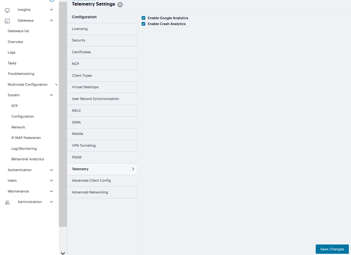
FIGURE 249 Telemetry
Advanced Client Configuration
This topic describes the XML advanced client configuration that can be used by the ICS administrator to configure the custom settings, which are meant to solve a specific customer scenario without changing the ICS admin console. Admin can set these custom settings in the form of XML input through the Advanced Client Configuration UI feature. Ivanti Secure Access clients supporting these custom settings will consume them when connecting to this ICS, and the same would be applied on the client ma-chines. This feature will minimize the number of changes going into the ICS admin console, in order to fulfill a custom requirement of a specific customer.
If the administrator configures the Ivanti Connect Secure sever with the following XML input in “Advanced Client Configuration for Ivanti Secure Access Client” option, it will ignore TCP MSS options while calculating the virtual adapter MTU on client side.
To add advance client config:
Navigate to System > Configuration > Advanced Client Configuration to display the configuration page.
Enter the following XML input in Advanced Configuration for Ivanti Secure Access Clients.
 <advanced-config>
  <version> version </version>
  <desktop-client-config>
   <layer3-connection-config>
   <adapter-config>
    <ignore-tcp-mss>TRUE</ignore-tcp-mss>
   </adapter-config>
   </layer3-connection-config>
  </desktop-client-config>
</advanced-config>
Click Save Changes.
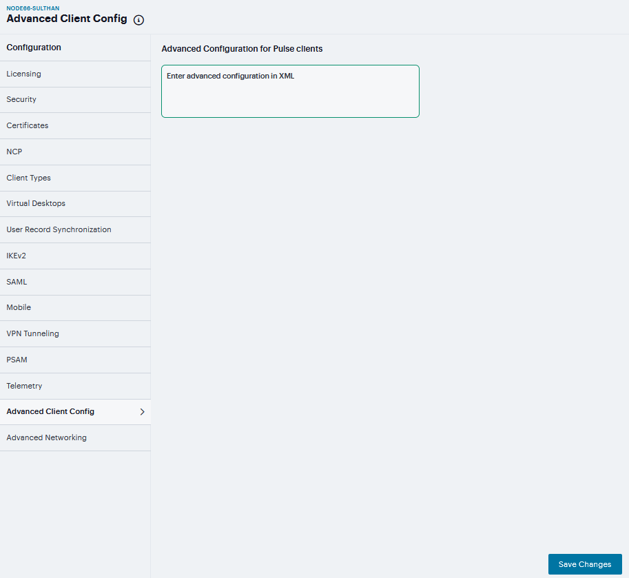
FIGURE 250 Advanced Client Configuration
The advanced configuration setting “ignore-tcp-mss” is Layer3 Adapter configuration setting and this will be consumed by the Ivanti Secure Access client as part of the IpsecConfig.
Note
This “ignore-tcp-mss” setting is applicable for the virtual adapter MTU calculation only for IPv4. By default, the setting is always false, and therefore the TCP MSS options are always considered for MTU by default. Admin has to explicitly set the ignore-tcp-mss setting to TRUE (case insensitive), to ignore TCP MSS.
Advanced Networking Configuration
The NTP, SNMP, Syslog, and Log archiving services are set to send the traffic through Management port by default. In case the Management port is not available, the traffic is routed through Internal port. Now, an administrator can modify the settings of NTP and other services to any physical inter-face.
The following procedure describes the steps to configure the ports for the services. Before you proceed, ensure the External and Management ports are enabled for use in the network settings.
To configure Service Traffic Port Options
Navigate to System > Configuration > Advanced Networking.
For the individual service, select the required port from the drop-down list.
Click Save Changes.
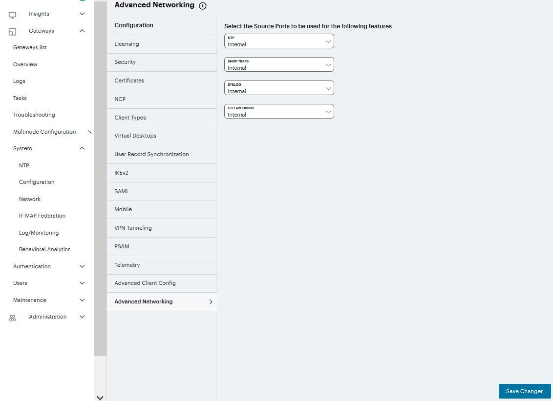
FIGURE 251 Advanced Networking
In a cluster environment, when a node joins the cluster, configuration of the node is replaced with the configuration of other nodes in the cluster.
IF-MAP Federation
You can configure a Ivanti Policy Secure device to store user session information for other Ivanti Policy Secure and Ivanti Connect Secure devices. Federation allows users to authenticate to a single Ivanti Connect Secure or Ivanti Policy Secure, and then access resources that are protected by any number of Ivanti firewall devices known as Infranet Enforcers that are controlled by different Infranet Controllers. Federation enhances network performance. If a user is required to log in to multiple Ivanti Connect Secure or Ivanti Policy Secure devices during the course of a day to access different resources, each device must perform authentication and Host-Checking, often with periodic Host Checker updates throughout the day. The overhead can lead to decreased performance not only on the devices, but also on the network and the endpoint. Imported IF-MAP sessions eliminate redundant logins and Host Checks.
Federation on the device uses the standard IF-MAP (Interface for Metadata Access Point) protocol to share session information and other data between connected devices over distributed networks. IF-MAP is a protocol defined by the Trusted Network Connect Working Group (TNC-WG) as a standard interface between different network elements and devices. Federation is accomplished using an IF-MAP server and IF-MAP clients.
It is important as an administrator to understand the fundamental underlying communication method for data transmission in a Federation network over IF-MAP. Policies that you configure on the device permit this communication. In a federated network, the IF-MAP server functions as the repository, or data store for IF-MAP clients to use for publishing information regarding activity on the network. For example, IF-MAP clients can publish information about sessions on the network, and Juniper Networks IDP devices can communicate information about potential threats to the IF-MAP client for publishing. IF-MAP clients can search for information about sessions or threats, and an IF-MAP client can establish a subscription so the IF-MAP server notifies the client when other clients publish new or changed information. In addition, IF-MAP clients can purge data that is no longer valid. All transactions are initiated by the IF-MAP client.
Overview
You can configure the system as an IF-MAP client for an IF-MAP server. You configure an Infranet Controller as an IF-MAP server. Any endpoint sessions with an IP address created on an IF-MAP server are automatically published to that IF-MAP server.
You can create source IP policies for endpoints that authenticate to the device to permit access to resources behind Infranet Enforcers (ScreenOS Enforcers and Ivanti Policy Secure s). Session-Export policies that you configure on the IF-MAP clients allow the clients to publish endpoint user data to the IF-MAP server. Devices that are IF-MAP clients can subscribe to the information on an IF-MAP server. When a user accesses the device that is configured as an IF-MAP client, the client publishes basic session information, including the IP address, username and roles, to the IF-MAP server. The server stores the information as metadata. Other IF-MAP clients in the network can poll the server for metadata when session information is needed as a result of an endpoint attempting to access protected resources behind an Infranet Enforcer.
When an authenticated user from the device that is configured as an IF-MAP client attempts to access resources that are protected by an Infranet Enforcer for an Infranet Controller that is also configured as an IF-MAP client, the Infranet Controller automatically provisions an auth table entry for the user on the Infranet Enforcer to allow access without requiring the user to authenticate to the Infranet Controller.
The Infranet Enforcer as an IF-MAP client subscribes to session information and other data for the endpoint based on the originating IP address. The authenticating device (the original IF-MAP client) publishes any changes in session parameters to the IF-MAP server. Since the Infranet Controller that is protecting the accessed resources subscribes to the metadata on the Federation server, session information is always current.
The Infranet Enforcer allows or denies traffic based on the resource access policies that are configured on the Infranet Controller to which it is connected.
You configure server settings on the Infranet Controller that will be the IF-MAP server. You configure client settings on each of the Ivanti Connect Secure and Infranet Controller devices and that will be connected in the network.
You must identify the IF-MAP server to each IF-MAP client. To add the server, you specify the IF-MAP URL of the server and how to authenticate to the server. Match the URL and security settings to equal those on the IF-MAP server(s) to which the IF-MAP client will connect.
To configure IF-MAP client settings on the devices that will be IF-MAP clients:
Log into the nSA as a Tenant Admin.
From the ICS menu, click the Gateway > Gateway List and then select any standalone ICS Gateway and Cluster node.
Navigate to System > IF-MAP Federation > Overview.
Select the Enable IF-MAP Client check box.
Type the Server URL for IF-MAP Web service on the IF-MAP server. Append the server URL with /dana-ws/soap/dsifmap for all Ivanti IF-MAP servers.
Select the client Authentication method: Basic or Certificate.
If you select Basic, enter a Username and Password. This is the same as the information that was entered on the IF-MAP server.
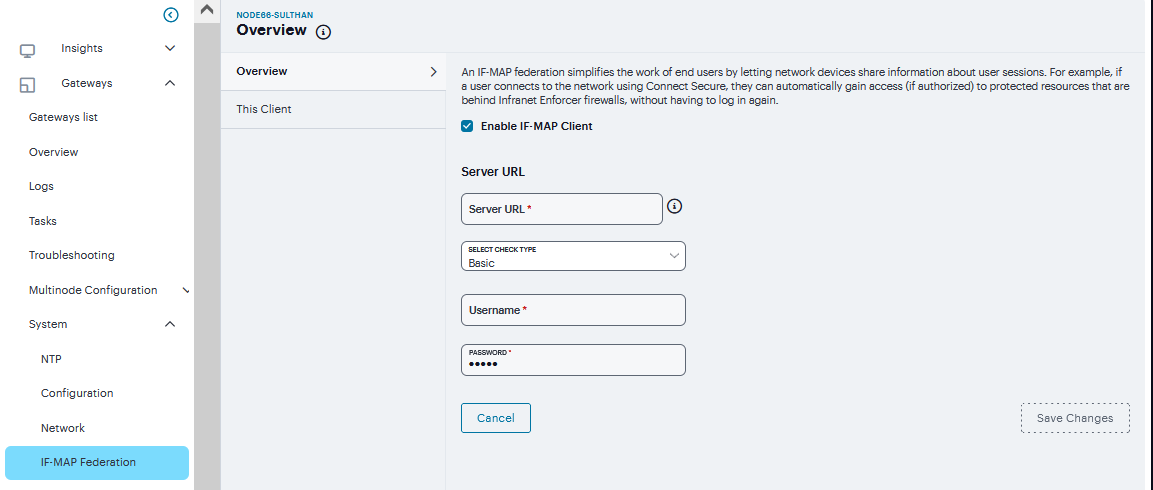
FIGURE 252 Basic
If you select Certificate, select the Device Certificate to use.
Ensure that the certificate of the CA that signed the IF-MAP server certificate is added from the System > Configuration > Certificates > Trusted Server CA page.
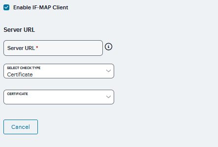
FIGURE 253 Certificate
The IF-MAP client validates the IF-MAP server certificate: if validation fails, the connection fails. Ensure that the hostname in the IF-MAP URL on the client machine matches the hostname of the server certificate on the IFMAP server, and that the CA that signed the server certificate is configured as a trusted server CA on the IF-MAP client.
Click Save Changes.
This Client
By default, Session-Import and Session-Export IF-MAP policies are configured to allow IF-MAP capabilities (the equivalent of roles) to be published to the IF-MAP server and retrieved from the IF- MAP server, provided there are matching roles on each IF-MAP client. You can open new Session-Import and Session-Export policies on each device, and then name and close the policies. Any matching roles that the IF-MAP clients in the federated network have can be used to access resources.
By default, advanced policy actions are not visible unless you click the advanced options links on the Session-Export and Session-Import policy pages. In default mode, you configure Session-Export and Session-Import policies using IF-MAP capabilities and roles. Device attributes, IF-MAP roles and identities can be accessed through the advanced options links. IF- MAP capabilities and Connect Secure roles should provide the functionality that most IF-MAP Federation requires.
Session-Export Policies
In a Layer 2 environment, session information on the IF-MAP server includes a MAC address. If an export policy specifies an Administrative Domain, the domain is associated with the MAC address published to the IF-MAP server (the administrative domain is also associated with the identity published to the IF-MAP server).
A DHCP server assigns an IP address to the endpoint after authentication. An IF-MAP enabled DHCPr server publishes an ip-mac link to IF-MAP, associating the endpoint’s IP address with its IF-MAP session information.
Including administrative domains in MAC addresses allows the ip-mac link to be created based on the administrative domain.
If your IF-MAP Federated network spans different administrative domains, you should configure separate Session-Export policies for each domain to prevent MAC address spoofing. Each administrative domain should have an associated DHCP server and unique Session-Export policies.
Other aspects of the Session-Export policies within the IF-MAP Federated network can overlap.
To configure a Session-Export policy:
Log into the nSA as a Tenant Admin.
From the ICS menu, click the Gateway > Gateway List and then select any standalone ICS Gateway and Cluster node.
Navigate to System > IF-MAP > Session-Export Policies.
Click ‘+’ to create a new policy.
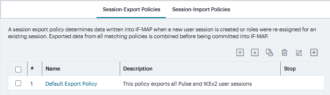
FIGURE 254 Session-Export Policies
Type a Policy Name, and optionally a Description.
Optionally, add Available Roles to the Selected Roles column to determine the roles for which this policy should apply. If you do not add any roles, the policy applies to all sessions. However, if you have non-interactive devices such as printers that do not need access, you may want to manually add roles and exclude those roles with non-interactive devices.
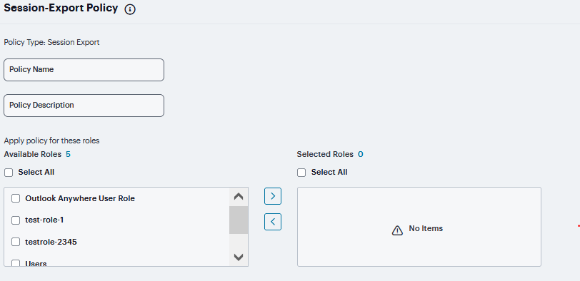
FIGURE 255 Roles
Under Policy Actions, Select Set IF-MAP Capabilities and choose the applicable roles.
Copy matching roles - Selecting this action copies all of the user roles that match the roles specified in the Roles section of this policy into the IF-MAP capabilities data.
Copy ALL roles - Selecting this action copies all of the roles from the user session to the IF-MAP capabilities data.
Set capabilities specified below - Enter capabilities, one per line.
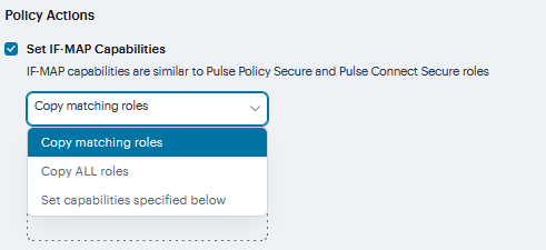
FIGURE 256 Capabilities
Select Stop processing policies when this policy matches to specify that when this policy is matched, no more Session-Export policies should be applied.
Click Save Changes, or continue to configure Advanced Actions.

FIGURE 257 Stop Processing Policies
Click the View Advanced Actions link. Additional options appear on the page.
Set IF-MAP Identity - If this action is chosen, enter the Identity and select an Identity Type from the menu. Identity is normally specified as <NAME>, which assigns the user’s login name. Any combination of literal text and context variables may be specified. If you choose other for Identity Type, enter a unique Identity Type in the Other text box.
Optionally type the Administrative Domain for the Session-Export policy. This optional field is applied to identity and MAC address data. One example for using this field is in a large network environment with several domains in which a username could be duplicated. By entering the domain, you ensure that the correct user is identified.
Set IF-MAP Roles - If this action is selected, select the applicable roles.
Copy matching roles - Selecting this action copies all of the user roles that match the roles specified in the Roles section of this policy into the IF-MAP capabilities data.
Copy ALL roles - Selecting this action copies all of the roles from the user session to the IF-MAP capabilities data.
Set roles specified below - Enter roles, one per line.
Set IF-MAP Device Attributes - Device attributes represent a passed Host Checker policy on the Infranet Controller or Connect Secure.
Copy Host Checker policy names - The name of each Host Checker policy that passed for the session is copied to a device attribute.
Set device attributes specified below - Type device attributes, one per line, into the text box.
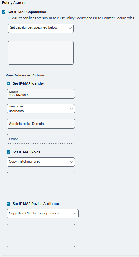
FIGURE 258 View Advanced Actions
Click Save Changes to save this advanced Session-Export policy.
You must create corresponding Session-Import policies that allow IF-MAP client Infranet Controllers that are connected to an Infranet Enforcer in front of protected resources to collect IF-MAP data from the IF-MAP server.
Session-Export Policies
The Session-Export policies that you create allow IF-MAP data that represents a session to be stored on the IF-MAP server. Session-Import policies specify how the Infranet Controller derives a set of roles and a username from the IF-MAP data in the IF-MAP server. Session-Import policies establish rules for importing user sessions from Connect Secure. Import policies allow you to match authenticated users with corresponding roles on the target device. For example, you might configure an Import policy to specify that when IF-MAP data for a session includes the “Contractor” capability, the imported session should have the “limited” role. Session-Import policies allow the Infranet Controller to properly assign roles based on information that the IF-MAP server provides. You configure Session-Import policies on IF-MAP client IVEs that are connected to an Infranet Enforcer in front of protected resources.
To configure a Session-Import policy:
Log into the nSA as a Tenant Admin.
From the ICS menu, click the Gateway > Gateway List and then select any standalone ICS Gateway and Cluster node.
Navigate to System > IF-MAP > This Client > Session-Import Policies tab.
Click ‘+’ to create a new policy.
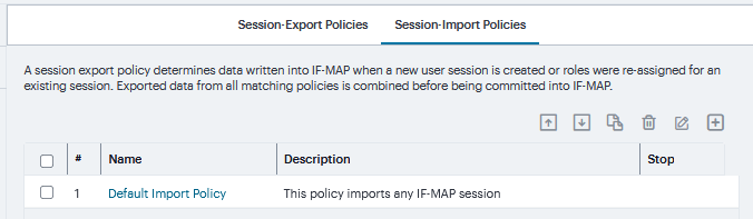
FIGURE 259 Session-Import Policies
Type a Policy Name, and optionally a Description.
Under Conditions when Policy Applies, Select Match IF-MAP Capabilities, enter one capability per line.
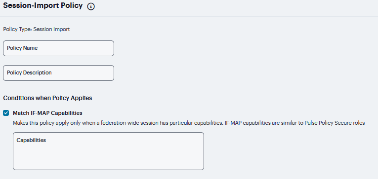
FIGURE 260 Conditions When Policy Applies
Click the View Advanced Conditions link. Additional options appear on the page.
Match IF-MAP Identity - If this action is chosen, enter the Identity and select an Identity Type from the menu. Identity is normally specified as <NAME>, which assigns the user’s login name. Any combination of literal text and context variables may be specified. If you choose other for Identity Type, enter a unique Identity Type in the Other text box.
Optionally select and type the Administrative Domain for the Session-Import policy. This optional field is applied to identity and MAC address data. One example for using this field is in a large network environment with several domains in which a username could be duplicated. By entering the domain, you ensure that the correct user is identified.
Match IF-MAP Roles - If this action is selected, then match then specified Roles below - Enter roles, one per line.
Match IF-MAP Device Attributes - Matches Device attributes passed Host Checker policy on the Infranet Controller or Connect Secure. Enter one Attribute, one per line.
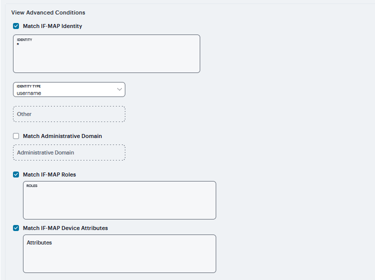
FIGURE 261 View Advanced Conditions
Optionally, Under Assign these roles and Click Use these roles add Available Roles to the Selected Roles column to determine the roles for which this policy should apply. If you do not add any roles, the policy applies to all sessions.
To copy If-Map Capabilities Select Copy IF-MAP Capabilities and select the capabilities. If Specified capabilities or All capabilities other than those specified below is selected, then enter one capability per line in the text box.
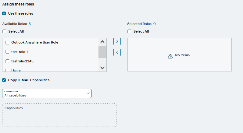
FIGURE 262 Assign these roles
Select Stop processing policies when this policy matches to specify that when this policy is matched, no more Session-Import policies should be applied.
Click Save Changes or continue to configure Advanced Assignment Option.
Click the View Advanced Assignment Option. Additional options appear on the page.
Click Copy IF-MAP Roles - If this action is selected, then select the applicable roles.
If Specified roles or All roles other than those specified below is selected, then enter one role per line in the text box.
Click Save Changes.
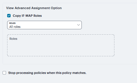
FIGURE 263 View Advanced Assignment Option
Log/Monitoring
The system generates event logs related to system performance, administrator actions, network communications, access management framework results, user sessions, and so forth. The system supports the following log collection methods:
Local log collector and log viewer.
Reporting to syslog servers.
Reporting to SNMP servers.
The following table lists the Event Log Severity Levels:
Severity Level |
Description |
|---|---|
Critical (level 10) |
The system cannot serve user and administrator requests or loses functionality to a majority of subsystems. |
Major (levels 8-9) |
The system loses functionality in one or more subsystems, but users can still access the system for other access mechanisms. |
Minor (levels 5-7) |
The system encounters an error that does not correspond to a major failure in a subsystem. Minor events generally correspond to individual request failures. |
Info (levels 1-4) |
The system writes an informational event to the log when a user makes a request or when an administrator makes a modification. |
In addition to managing system logs, you can use the admin console to configure collection of client-side logs, including:
Host checker
Windows Secure Application Manager
Java Secure Application Manager and Applet Rewriting
VPN Tunneling
Terminal Services
Virtual Desktops
Events to Log
To configure log event categories:
Select System > Log/Monitoring.
Click the Settings tab to display the configuration page.
Complete the configuration as described in table.
Click Save Changes.
Note
To configure log events for each local log category, you must perform this procedure on each local log tab: Events, User Access, and Admin Access.
The following table lists the Log Events Settings:
Settings |
Guidelines |
|---|---|
Maximum Log Size |
|
Max Log Size |
|
Archiving |
Click the Archiving link to display the configuration page for Archiving jobs, including log archiving. |
Select Events to Log - Events Tab |
|
Connection Requests |
Log events related to connection requests. |
System Status |
Log events related to changes in system status. |
Rewrite |
Log events related to rewrite policies. |
System Errors |
Log events related to system errors. |
Statistics |
Log user access statistics reported on the System > Log/Monitoring > Statistics tab. If you disable the Statistics option, the statistics are not written to the log file, but are still reported on the statistics page. |
License Protocol Events |
Log events related to licensing. |
Reverse Proxy |
Logs events related to reverse proxy information.
|
Select Events to Log - User Access Tab |
|
Login/logout |
Log events related to sign in and sign out. |
SAM/Java |
Log events related to user access to SAM/Java in the local log file. |
User Settings |
Log events related to changes to user settings in the local log file. |
Client Certificate |
Log events related to certificate security. |
IF-MAP Client User Messages |
Log events related to IF-MAP. |
Ivanti Secure Access Client Messages |
Log events related to Ivanti Secure Access clients. |
HTML5 Access |
Log events related to HTML5 access. |
Web Requests |
Log events related to user access to web. |
File Requests |
Log events related to user access to files. |
Secure Terminal |
Log events related to user access to secure terminal. |
VPN Tunneling |
Log events related to user access to VPN tunneling. |
SAML |
Log events related to user access to SAML. |
System Too Busy |
Log events related to ICS overload. |
Unauthenticated Web Requests |
Log events related to web requests before authentication. By default, this check box is disabled.
|
Select Events to Log - Admin Access Tab |
|
Administrator changes |
Log events related to configuration changes. |
Administrator logins |
Log events related to administrator access. |
License changes |
Log events related to licensing. |
System Errors |
Log events related to system errors.
|
Syslog Servers |
click ‘+’ to add new logs. Complete the configuration as described in below rows. You can specify multiple syslog servers. |
Server name/IP |
|
Facility |
Select a syslog server facility level (LOCAL0-LOCAL7). Your syslog server must accept messages with the following settings: facility = LOG_USER and level = LOG_INFO. |
Type |
|
Client Certificate |
(optional) If you select TLS from the Type menu and your remote syslog server requires client certificates, select the installed client certificate to use to authenticate to the syslog server. Client certificates are defined in the Configuration > Certificates > Client Auth Certificates page. Client certificates must be installed on the device before they can be used. There is no fallback if a connection type fails. |
Filter |
Select a filter format. Any custom filter format and the following predefined filter formats are available:
|
Source Interface |
Select the source port type for the syslog server:
|
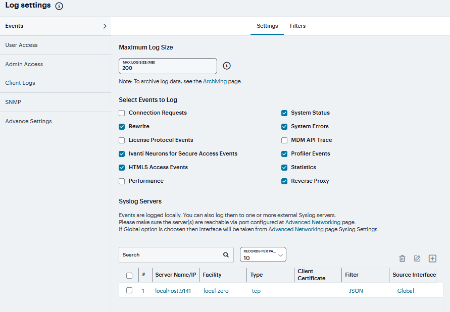
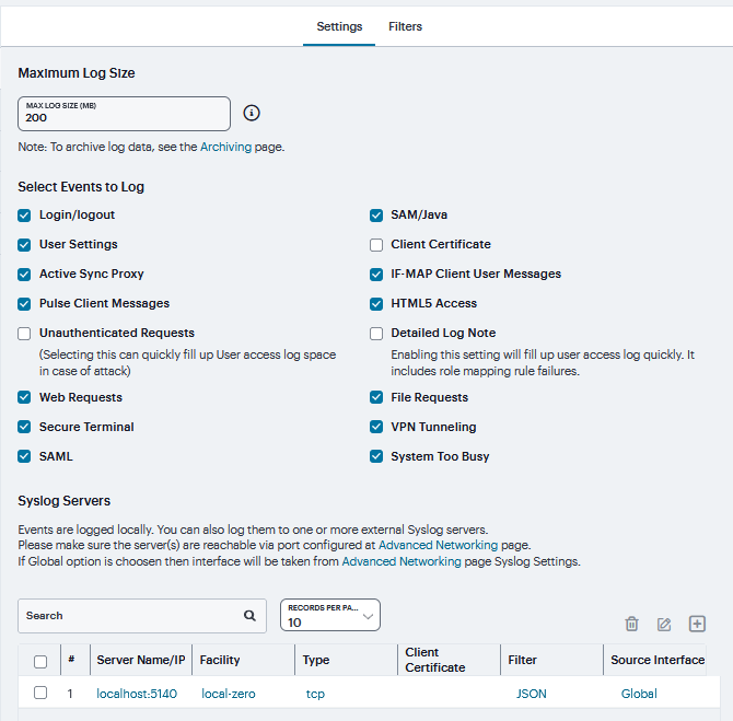
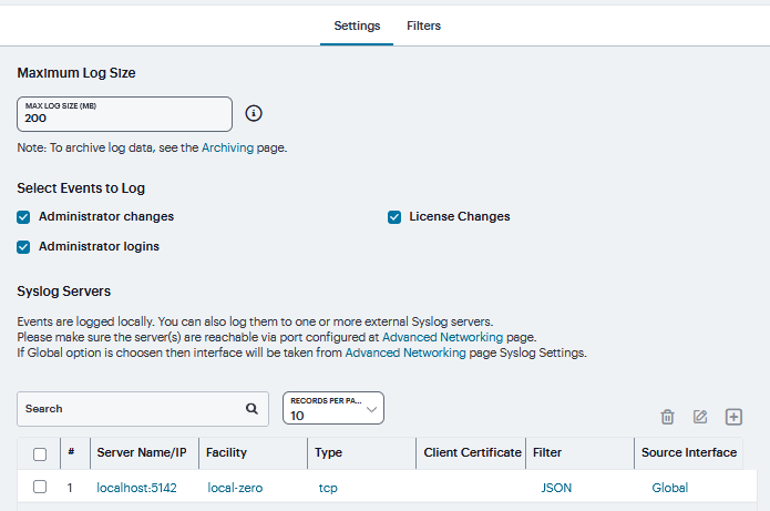
Log Filters
If desired, you can create custom log collection filters to change the records displayed or exported. For example, it is common to see administrators use a filter for RADIUS accounting logs. This filter allows only the accounting log message, and it puts the entire message in a comma separated list. The order of the filtered message is: Date, Time, User, Realm, “List of Roles”, NAS-ID, Acct-Status, Auth-Type, Attr-Value1, Attr-Value2, Attr-Value3.
Accounting attribute messages are different from authentication attribute messages in that the attribute name is not printed in the log message, but a comma is inserted for every attribute to be logged, even if it is not present.
To view the configuration of predefined log format filters:
Navigate to System > Log/Monitoring.
Click the Events / User Access / Admin Access tab.
Click the Filter tab to display the log filters page.
Click the hyperlinked name of the filter to display its configuration page. You cannot edit the predefined filter named Standard, but you may edit the predefined WELF filters and any other custom filters that appear in the list.
Click ‘+’ to display the configuration page for creating new filter.
Complete the configuration as described in table.
Click Save Changes.
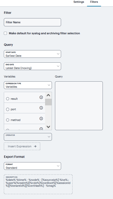
FIGURE 267 Log Filter
Settings |
Guidelines |
|---|---|
Filter Name |
Specify a name that is helpful to you and other administrators in understanding usage for your custom filter. |
Make default |
Make the filter the default on syslog and archiving configuration pages. |
Query |
|
Start Date |
Enter a start date. Click Earliest Date to write all logs from the first available date stored in the log file. |
End Date |
Enter an end date. Click Latest Date to write all logs up to the last available date stored in the log file. |
Query |
|
Export Format |
Select an export format:
|
Note
Log query filters change only the data displayed (or rows exported). Log format filters change only the data displayed (or columns exported). Use of filters does not affect the log data that has been collected.
Client Side Log
Client-side logging is not enabled by default. If necessary, you can enable client-side logging to troubleshoot any client application issues.
To enable client side logging:
Select System > Log/Monitoring.
Click the Client Logs tab to display the configuration page. Complete the configuration as described in Table.
Click Save Changes.
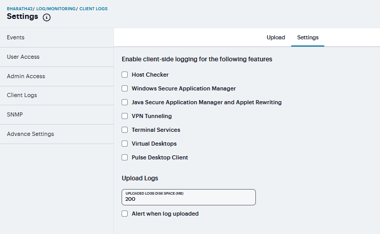
FIGURE 268 Client Side Log
Upload tab displays Uploaded Logs Details
Settings |
Guidelines |
|---|---|
Host Checker |
Select this option to enable client-side logging of Host Checker. |
Windows Secure Application Manager |
Select this option to enable client-side logging of PSAM. |
Java Secure Application Manager and Applet Rewriting |
Select this option to enable client-side logging of JSAM and applet. |
VPN Tunneling |
Select this option to enable client-side logging of VPN tunneling. |
Terminal Services |
Select this option to enable client-side logging of terminal services. |
Virtual Desktops |
Select this option to enable client-side logging of virtual desktops. |
Ivanti Secure Access Desktop Client |
Select this option to enable client-side logging of Ivanti Secure Access desktop clients. |
Upload logs |
|
Upload logs disk space (MB) |
Specify the amount of disk space (in Megabytes) you want to allocate for uploaded client log files. You can allocate disk space from 0 to 200 MB. |
Alert when log uploaded |
Select this option to receive an alert message when an end user pushes a log file. |
SNMP
If you prefer, you can use a third-party SNMP manager, such as HP OpenView, to monitor system health. The system supports SNMP v2c and SNMPv3. The system supports two users to be registered with an SNMP engine with different authentication and privilege settings.
To configure the SNMP agent:
Select System > Log/Monitoring.
Click the SNMP tab to display the SNMP configuration page.
Complete the configuration as described in Table.
Click Save Changes.
Settings |
Guidelines |
||||||||||||||||||||
|---|---|---|---|---|---|---|---|---|---|---|---|---|---|---|---|---|---|---|---|---|---|
MIB File |
Use the Ivanti MIB file link to download the device management information base MIB file. You add this file to your SNMP manager configuration. |
||||||||||||||||||||
SNMP Version |
|
||||||||||||||||||||
Agent Properties |
|||||||||||||||||||||
SNMP Queries |
Select to support SNMP queries. Selecting this option enables the SNMP Diagnostic Log utility in the Troubleshooting > Monitoring > Diagnostic Logs page. |
||||||||||||||||||||
SNMP Traps |
Select to send SNMP traps. Selecting this option enables the SNMP Diagnostic Log utility in the Troubleshooting > Monitoring > Diagnostic Logs page. |
||||||||||||||||||||
System Name |
Specify a system name. |
||||||||||||||||||||
System Location |
Specify a location. |
||||||||||||||||||||
System Contact |
Specify a system contact |
||||||||||||||||||||
Community String |
|
||||||||||||||||||||
SNMPv3 Configuration |
|||||||||||||||||||||
Username |
Specify the SNMPv3 username. The User-Based Security Model (USM) is the default Security Module for SNMPv3. The system supports two users to be registered with an SNMP engine. Editing the SNMPv3 user attributes overwrite any already registered SNMPv3 user. The SNMPv3 user must have read-only access on all MIBs supported by the system. SNMPv3 user configuration attributes can also be used for SNMP traps.
|
||||||||||||||||||||
Security Level |
|
||||||||||||||||||||
Trap Thresholds |
Setting a threshold value to 0 disables that respective trap. |
||||||||||||||||||||
Check Frequency |
Specify the frequency in seconds for sending traps. The default is 180 seconds. |
||||||||||||||||||||
Log Capacity |
Specify the percent of log space used. The default is 90%. |
||||||||||||||||||||
Users |
Specify the frequency in seconds for sending traps. The default is 180 seconds. |
||||||||||||||||||||
Physical Memory |
Specify the percent of physical memory used. The default is 0 (not reported). |
||||||||||||||||||||
Swap Memory (Virtual Memory) |
Specify the percent of swap memory used. The default is 0 (not reported). We recommend you monitor swap memory to alert you to potential memory issues. The threshold for traps for physical memory usage might be reached even if the system is not experiencing any difficulties. |
||||||||||||||||||||
Disk |
Specify the percent of disk utilization. The default is 80%. |
||||||||||||||||||||
CPU |
Specify the percent of CPU utilization. The default is 0 (not reported).
|
||||||||||||||||||||
Optional Traps |
|||||||||||||||||||||
Critical Log Events |
Send traps when the system logs critical events. |
||||||||||||||||||||
Major Log Events |
Send traps when the system logs major events. |
||||||||||||||||||||
Save SNMP Settings |
Click Save Changes to update the SNMP agent configuration. The page is refreshed and displays the SNMP engine ID. If the configuration is changed to move from SNMP v2c to SNMP v3, the system generates and displays two engine IDs. |
||||||||||||||||||||
SNMP Servers |
|||||||||||||||||||||
Hostname / IP address |
Specify the hostname or IP address for the SNMP servers to which the system will send any traps it generates. |
||||||||||||||||||||
Port |
Specify the port for the SNMP server. Typically, SNMP uses port 162. |
||||||||||||||||||||
Community (v2c) / User (v3) |
Specify the community/user string (if necessary).
|
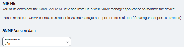
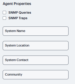
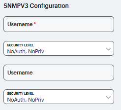
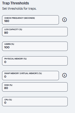
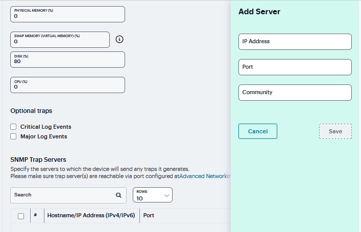
Keep the following configuration tips in mind when you configure your SNMP manager to listen for this SNMP agent:
Add the Ivanti MIB file to the SNMP manager configuration.
If using SNMPv2c, the community string configuration for the SNMP manager and SNMP agent must match.
If using SNMPv3, the SNMPv3 user configuration for the SNMP manager and the SNMP agent must match.
If using SNMPv3, you must specify the Authoritative Engine ID for SNMPv3 traps that was generated when you saved the SNMP agent configuration.
Advanced Settings
This option helps to configure fault tolerance on each configured TCP and TLS syslog server available. Fault tolerance is supported only for TCP and TLS syslog servers. UDP syslog servers cannot be configured for fault-tolerance. This functionality helps the syslog server to recover the logs lost during a disconnect. The administrator can configure fault-tolerance on syslog servers by enabling this option from the admin UI. ICS/IPS reads the lost pending logs during a disconnect from the log disk and transports them to the syslog server on a reconnect. Fault tolerance is supported only for the syslog servers configured under the following log-types:
Events
User Access
Admin Access
Note
Fault tolerance is node-specific. In case of clusters, the setting needs to be enabled/disabled by logging into each of the cluster members. Fault tolerance is supported only for TCP and TLS syslog servers. UDP syslog servers cannot be configured for fault tolerance.
To configure advance settings to a TCP and TLS syslog server:
Navigate to System > Log/Monitoring.
Click the Advance Settings tab to display the configuration page.
Complete the configuration as described in Table.
Click Save changes.
Note
This feature is limited to configuring fault tolerance settings of an existing syslog server; and cannot be used to create or delete a new syslog server.
Settings |
Guidelines |
|---|---|
Syslog Server Fault Tolerance |
|
Syslog Server |
Lists the existing Syslog servers. |
Type |
Specifies if the Syslog server is a TLS or TCP type. |
Fault Tolerance |
Tolerates the loss of network connection to a TCP/TLS syslog server for a brief period (maximum of 4 hours) by sending the logs missed during the disconnect time. Click the check box to enable this option. Fault-tolerance is disabled by default on any syslog server. |
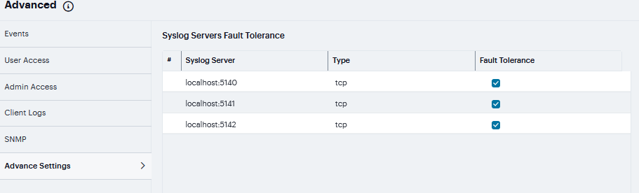
FIGURE 274 Advanced Settings
Behavioral Analytics
Behavioral Analytics feature analyzes user’s action along with other context data to derive conclusions about any anomalous activities. It provides information/visibility based on real time user or device context thus helping in advanced attack detection and helps in proactive policy-based enforcement.
The Behavioral Analytics feature addresses the following types of anomaly detection:
- User/device is prompted for second level of authentication based on the threat profile determined for the corresponding user/device.
Below are some scenarios where second level of authentication is required:
User authenticating from new device: This is detected by using the device MAC address.
User authenticating from new location: Location details are obtained by using the location configurations.
Benefits
- ICS monitors the traffic from users and helps in determining the possible anomalous activities such as:
If the user is authenticating from a new device / new location.
If the device traffic is different from previous instances.
Data collected as part of Behavior Analytics is stored so that it can be used later for determining the anomalies.
To enable behavioral analytics:
Log into the nSA as a Tenant Admin.
From the ICS menu, click the Gateways > Gateways List and then select any standalone ICS Gateway or Cluster node.
Navigate to System > Behavioral Analytics > Configuration.
Under Configurations, select Enable Behavioral Analytics.
For enabling Adaptive Authentication, select Enable data collection during authentication of devices and users.
Click Save Changes.
FIGURE 275 Behavioral Analytics
In case you have a Fresh Installation of ICS, then it will NOT have UEBA package by default with it. Please add the UEBA package before using Adaptive Authentication.