Working with Gateways
Introduction
After you have successfully logged into the Ivanti Neurons for Zero Trust Access (nZTA) Controller as a Tenant Admin user (see Logging in as a Tenant Administrator), you can start the configuration of your nZTA platform by adding Gateways.
nZTA supports two main Gateway types, depending on your subscription:
ZTA Gateway
Ivanti Connect Secure (ICS) Gateway
This chapter covers functionality relating to a ZTA Gateway only. For details pertaining to a ICS Gateway, see instead the “ICS Tenant Admin Guide” in the nZTA documentation portal.
Note
To learn more about ZTA Gateways and their relationship with the other dimensions of a Secure Access Policy, see Deploying Gateways.
A Gateway controls access to the applications at the location to which it is deployed. This location could be a physical datacenter, a private or public cloud-based service, or some hybrid combination. Each Gateway communicates with the Controller to ensure that access requests are authenticated. A Gateway must be contactable by both the Controller and the applications that reside there. See Configuring Networks in your Gateway Datacenter.
The process of defining a Gateway on the Controller produces a package of settings, known as a Gateway definition, that you publish to the Gateway virtual machine instance during deployment. These settings enable the Gateway to establish communication with the Controller.
Note
Ensure the Gateway virtual machine instance does not exist prior to creating your Gateway definitions on the Controller. All ZTA Gateways must be deployed from the Controller directly. The Gateway definition file is designed to be published to a new virtual machine Gateway instance during its initial deployment.
To register a new Gateway with the Controller, use the Tenant Admin portal. The Controller requires basic identification and networking details for the Gateway instance, and in return provides a downloadable Gateway definition file.
Note
A Gateway definition file is valid for 24 hours. If this period expires, you must replace the Gateway to generate a new Gateway definition file.
When you deploy the Gateway virtual machine instance in your on-premise or cloud infrastructure, you apply the definition file as configuration data. At launch time, the Gateway attempts to contact and register itself with the Controller, establishing a link between the Gateway record in the Controller and the actual virtual machine instance. Any subsequent policy changes made on the Controller are automatically synchronized out to all Gateways.
You can choose a single Gateway (or Gateway Group) to act as a default Gateway. A default Gateway handles all requests from applications that are not referenced by any secure access policy. See Viewing and Monitoring Gateways in the Controller.
Note
Ivanti Secure Access Client Linux variants do no currently support the use of a default gateway.
After you have registered your Gateways with the Controller, you can:
View performance and usage graphs
See activity logs
View task lists
Establish Gateway Groups for High Availability
Manage version upgrades
Replace Gateway instances registered with the Controller
To learn more, see Viewing and Monitoring Gateways in the Controller.
High Availability
nZTA allows you to deploy multiple Gateways in front of the same set of applications or resources to support high availability. This arrangement can be used to provide scaling, redundancy, and load distribution for your application delivery. To learn more, see Using Gateway Groups for High Availability.
High availability is implemented in the Controller through Gateway Groups. You add individual Gateways to a group, and then associate the group with your Secure Access Policy. To learn more about adding Gateway Groups, see Adding Gateway Groups for High Availability.
Gateway Deployment Workflows
nZTA supports Gateway virtual machine instances deployed in the following environments:
VMware vSphere: see Workflow: Creating a Gateway in VMware vSphere.
Amazon Web Services (AWS): see Workflow: Creating a Gateway in Amazon Web Services.
Microsoft Azure: see Workflow: Creating a Gateway in Microsoft Azure.
KVM on OpenStack: see Workflow: Creating a Gateway in KVM/OpenStack.
Google Cloud Platform: see Workflow: Creating a Gateway in Google Cloud Platform.
You can choose any single Gateway (at v21.1 or later) or Gateway Group to act as a default Gateway. A default Gateway handles all requests from applications that are not referenced by any secure access policy. See Configuring a Default Gateway for Application Discovery.
Note
Each process described in this chapter contains prerequisites that correspond to the latest supported Gateway versions for this release. To deploy older supported Gateway versions, substitute in the file paths and names with the version you want to use. To learn more about the supported Gateway images for this release, see the Release Notes or contact your support representative.
Configuring Networks in your Gateway Datacenter
ZTA Gateways deployed in your cloud or on-premise datacenter require the availability of a number of network interfaces and ports to operate correctly. You require the following primary interfaces defined in your Gateway virtual machine instance:
External network interface: Configured with a public subnet IP address and used for external client access to the applications deployed in that datacenter. Use this IP address during the process of creating your Gateway record on the Controller.
Internal network interface: Configured with a private subnet IP address and used for internal connections to the deployed applications, and for external communication with the Controller.
(Optional) Management network interface: Configured with an IP address and port on a further, separate, network subnet for deployments where a specific management interface is required.
Note
When the management interface is enabled, the Gateway communicates with the Controller through this interface instead. In this scenario, the Gateway still uses the internal network interface for DNS resolution and NTP server communication. As such, the Gateway DNS server should resolve the Controller and NTP server FQDNs through the internal interface (internet access is required).
ZTA Gateway template images contain parameters and settings for all required interfaces. You provide suitable configuration during the Gateway deployment workflows described in this chapter.
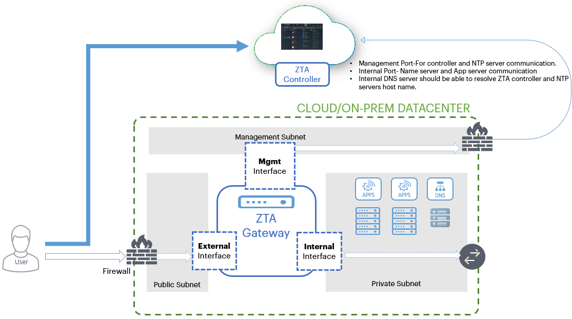
FIGURE 110 Gateway network connections in your cloud and on-premise datacenter
ZTA Gateway deployment using this topology offers the following attack protection benefits:
mTLS Communication: By using mTLS for communication with the Controller, your Gateways are protected from traffic originating from unauthorized and un-enrolled devices.
DMZ/DDoS Deployment: nZTA allows customers to deploy their own DDoS (Distributed Denial of Service) mitigations, either through network firewalls or DDoS services, before traffic reaches the ZTA Gateways deployed in your datacenter.
SSL inspection: If an administrator chooses to use SSL interception or deep inspection for traffic coming into the network or to back-end applications, this can be achieved on the internal Private Subnet side before traffic reaches your back-end application servers.
The Controller communicates with all registered Gateways to validate user sessions, and for reporting/analytics. Each Gateway maintains a timeout period of 5 minutes for validation of user sessions. If a Gateway fails to obtain a response from the Controller within this time limit, any new session authorization requests are denied. However, existing sessions remain connected to the applications and resources at that location until the user session expires. To learn more about user session expiry, see On-Demand and Simultaneous Connection Handling.
For all platforms, make sure the firewall rules for the Public Subnet in which your ZTA Gateway External Interface resides is configured to accept inbound client connections on TCP port 443.
Furthermore, make sure you configure the Network Gateway serving your Private Subnet to allow outbound traffic to the Controller in the following ways:
Allow outbound TCP traffic on port 443 to the Controller service
Allow outbound UDP traffic to the following Network Time Protocol (NTP) services:
time.windows.com (port 123)
time.nist.gov (port 123)
If you maintain your own DNS service at the datacenter, you can specify these details during Gateway deployment.
If you are planning to use your ZTA Gateway to serve SaaS (Software-as-a-Service) applications, configure your application to restrict inbound connections to your network gateway IP address. This ensures that your SaaS application can be reached only by clients connecting through the ZTA Gateway.
Using Dynamic IP Addressing to Profile Client Traffic
Note
This feature is supported for VMware (ESXi) and KVM Gateway types only.
Note
This feature is not supported for Gateway Groups.
A client establishes a secure tunnel to a Gateway in order to reach the applications and resources controlled by a Secure Access Policy. Traffic from the client passes through the tunnel to the Gateway, and from the Internal network interface on the Gateway to the application. The application or resource sees the client’s traffic as originating from the Gateway’s internal interface. This scenario is transparent to the client and application - the Gateway manages traffic back to the client using Network Address Translation (NAT) to map traffic on the internal interface to the client’s source IP address.
However, in some circumstances you might want to profile or monitor end-to-end traffic for your clients. This is difficult beyond the Gateway as traffic at the application appears to originate from the same source IP address (that of the Gateway internal interface). To facilitate this, nZTA includes the option to specify a pool of IP addresses in a dedicated subnet that the Controller can dynamically assign to client sessions. As a client sends traffic to an application or resource, the Gateway establishes a mapping from the tunnel IP address to one of the free IP addresses in the pool. This dynamically-assigned IP address is then used as the source IP address when sending client traffic to the application. The Gateway again uses NAT to manage the connections to each client.
You can configure dynamic IP addressing when adding a new Gateway or by editing an existing Gateway configuration. To learn more, refer to the Gateway Network Configuration workflows described in this chapter. To read more about how to enable Dynamic IP Addressing in an existing Gateway, see Editing Gateway Configuration.
To use dynamic IP addressing, the Controller requires you to define a unique address range for each applicable Gateway, using CIDR notation. For example, 192.0.2.0/24. You can add only one IP address range per Gateway.
Note
The allowed subnet range is 8-28. Make sure you select a subnet value that provides the amount of IP addresses necessary to map the expected number of clients connecting to the Gateway. If you exhaust the IP address range, your clients can still connect, although traffic profiling is not possible.
When configuring an address range, make sure this does not overlap with dynamic IP address ranges assigned to other Gateways.
White-listing Required IP Addresses for your Services
The Controller service uses a series of IP addresses and ports to facilitate access to the admin and user web consoles, for user enrollment, and for connections to ZTA Gateways. To ensure network access, make sure the following IP addresses and ports are white-listed (or added to the allowed list) in your network firewalls and routing infrastructure.
Select the IP addresses and ports for your corresponding region only:
North America:
52.186.44.249 (port 443)
52.188.33.186 (port 443)
Europe:
51.138.111.17 (port 443)
20.50.150.82 (port 443)
APJ:
20.44.238.229 (port 443)
20.44.237.67 (port 443)
Viewing and Monitoring Gateways in the Controller
To view, configure, and monitor the health of your deployed Gateways and Gateway Groups, use the Secure Access > Gateways section of the Controller Tenant Admin portal. The pages in this section remain inactive until you select a Gateway or Gateway Group.
Note
To view detailed analytics for your deployed Gateways, see also Monitoring ZTA Gateway Activity.
To view information for a Gateways or Gateway Group:
Log into the Controller as a Tenant Admin, see Logging in as a Tenant Administrator.
From the nZTA menu, click the Secure Access icon, then select Manage Gateways > Gateways List.
The All Gateways page appears, showing the full list of Gateway Groups and standalone Gateways currently configured on the Controller:
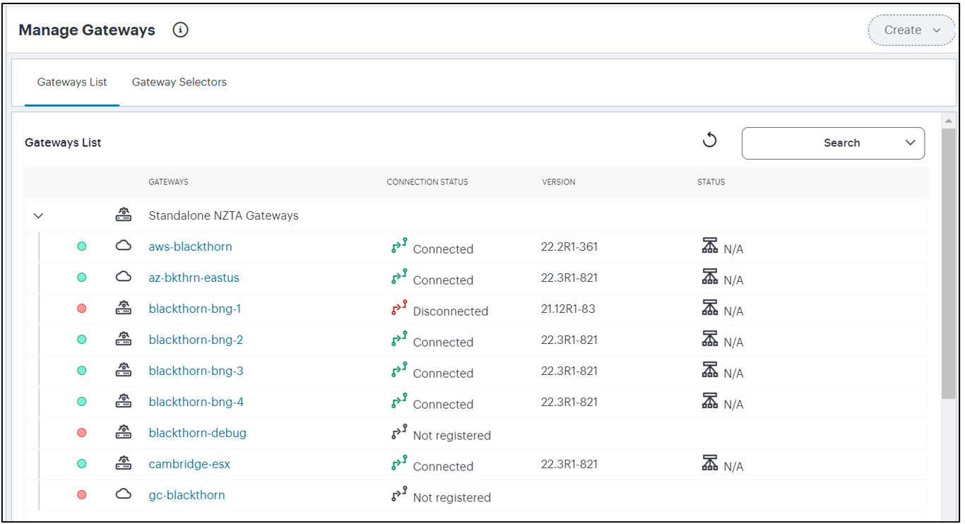
FIGURE 111 Viewing All Gateways
The health and status of each Gateway instance is denoted by the indicator colors used in the left-most column; green for connected/ready or red for disconnected/not ready. Unregistered Gateways are denoted by a missing indicator. Additional status information is given under Connection Status, with the current software Version, and the Status of any scheduled tasks.
Note
Use the Search box at the top enter a text search term to narrow the list to only matching Gateways and Gateway Groups.
Select a Gateway or Gateway Group from the list to view the Gateways Overview page.
This page provides further status and configuration details for the selected instance, as well as Performance, Concurrent Sessions, and Throughput usage graphs.
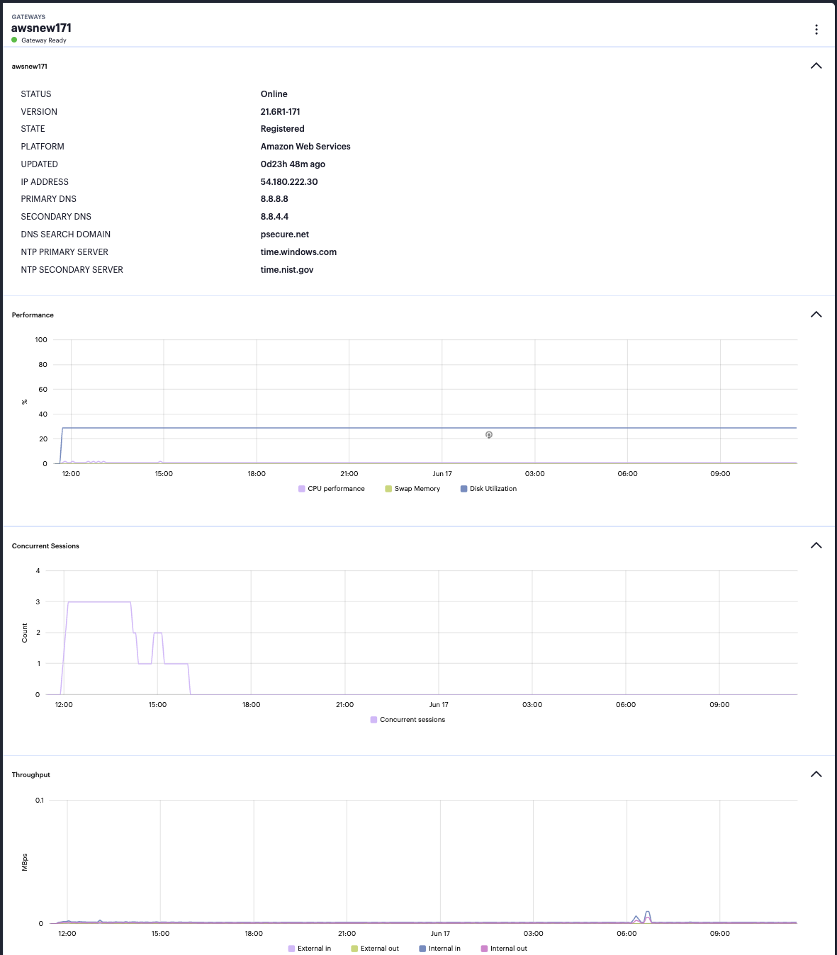
FIGURE 112 Viewing status, configuration, performance and Usage Graphs in the Gateway Overview page
Hover your pointer over a coordinate in each graph to view a tooltip showing detailed metrics for that moment.
Use the links in the Secure Access > Gateways menu to switch between Overview, Logs, Tasks, and Configuration pages for the selected Gateway or Gateway Group:
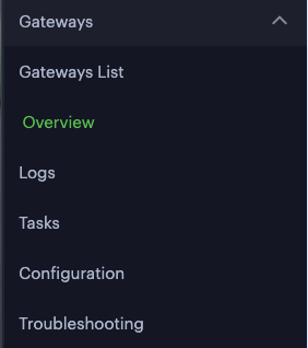
FIGURE 113 Selecting Gateway pages
To view the details for a different Gateway or Gateway Group, select Gateways List and choose an alternative instance.
Use the context menu icon at the top-right to access the Edit options applicable to the selected Gateway or Gateway Group:
FIGURE 114 Edit a Gateway or Gateway Group
The available options are dependent on the Gateway or Gateway Group you selected.
For Gateway Groups:
Edit Group: Edit details for the group, such as name, description, and load balancer public IP address.
Delete Group Only: Deletes the Gateway Group record, leaving any contained Gateways intact as standalone (ungrouped) instances.
Delete Group and Gateways: Deletes the Gateway Group and all Gateways contained in the group.
Note
This option appears only if there are existing Gateways in the Group.
Add Gateway to this Group: Add a registered standalone gateway to this group.
For Gateways:
Edit Gateway: Edit details for the Gateway, such as name, description, and public IP address. You can also select or reset the Use Management Port property.
Replace Gateway: Allows replacement of the Gateway virtual machine instance associated with this ZTA Gateway record. This option regenerates a Gateway definition file based on the existing networking details stored in the Gateway record, but with a new one-time token, to allow deployment and registration of a new virtual machine instance.
Note
A Gateway virtual machine deployed to replace an existing Gateway might be launched with a different public IP address on the external network interface. To update the public IP address setting stored for the Gateway in nZTA, use the Gateway Network Settings section of the Secure Access > Gateways > Configuration page. For more details, see Editing Gateway Configuration.
Remove from Group: Removes this Gateway from a Gateway Group.
Note
This option appears only if the selected Gateway is in a Gateway Group.
Delete Gateway: Deletes the Gateway record.
Upgrade to <version>: Upgrades the registered Gateway virtual machine instance to the specified version, see Upgrading Gateways.
Rollback to <version>: Reverts the registered Gateway virtual machine instance to the specified version, see Upgrading Gateways.
Note
The available menu options vary depending on whether the selected Gateway is registered and connected to the Controller.
Viewing Gateway Logs
The Logs page enables you to view the Access, Admin, and Event logs for the selected Gateway or Gateway Group.
To view Gateway logs:
Log into the Controller as a Tenant Admin, see Logging in as a Tenant Administrator.
From the nZTA menu, click the Secure Access icon, then select Gateways > Gateway List.
The All Gateways page appears, showing the full list of Gateway Groups and standalone Gateways currently configured on the Controller.
Select the required Gateway or Gateway Group.
The Gateways Overview page appears for the selected Gateway/Gateway Group.
Click the Secure Access icon, then select Gateways > Logs.
The Gateways Logs page appears.
This page supports the following features:
Select the log type you want to view in the Log Type drop-down list. Choose from:
Access Logs
Admin Logs
Event Logs
Set a Time Period over which the logs are shown. Use the time period selector to set a time period or range for your log results. Click the calendar (highlighted) to show the selector:
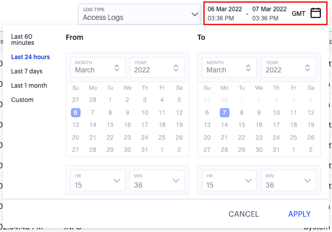
FIGURE 115 Setting a log time period
Set the time period you want to view using the available ranges at the top-left. Choose from:
Last 60 minutes
Last 24 hours (default)
Last 7 days
Last 1 month
Custom
For Custom, set a specific From and To to denote the start and end of your custom date/time range.
Note
The custom date/time calendar controls are enabled for only the Custom option. However, the calendar continues to identify the applicable start and end date-time for all predefined time periods.
To apply your changes, click Apply. The selected time period is displayed in the filter bar and data on the page updates accordingly.
Note
To configure the timezone, see Setting the Timezone.
Logs are refreshed automatically by changing the criteria. To manually refresh the log display, click the following icon:

FIGURE 116 Refreshing the page data
To change the fields displayed for each log line, use the following icon:

FIGURE 117 Show or hide log fields
In the field selector, click a field name to toggle between show or hide. A tick icon indicates a displayed field. After you are finished, click the context menu icon to close the selector.
Choose from the following fields:
Session identifier
Gateway identifier
Gateway name
Source IP address
User name associated with the event, where applicable
User device identifier, if available
A description of the event
Use the following icon to trigger the advanced filter selection:

FIGURE 118 Applying a filter to the log display
Use the filter to narrow down the displayed log records to your selected criteria. For example, to show only those log messages with a critical severity level, or pertaining to a specific user, or both. To learn about log filtering, see Filtering the Logs.
Use the following field to use search term highlighting. Enter a value into the search box, nZTA highlights all matches in the log display.

FIGURE 119 Highlighting a search term in the logs
To switch between the default and denser data views, use the following icon:

FIGURE 120 Setting the view density
To apply grouping to the displayed log records, click the following icon:

FIGURE 121 Group log records by selected criteria
This feature applies grouping to a selected field in the log record display, such that records are accumulated and grouped together under each unique data item identified in that field. Through grouping, an admin can quickly view the number of records of a particular type.
To learn more about record grouping, see Viewing Detailed Logs for a Chart.
To view a single log entry in a dedicated panel, click the log message text to activate the info-panel view:
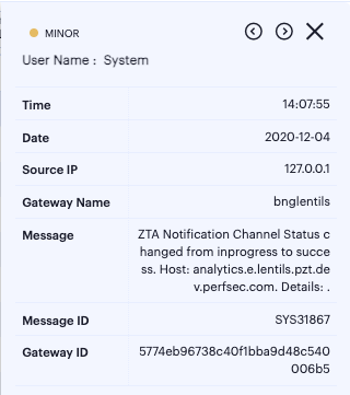
FIGURE 122 Viewing a single log entry in the info-panel
In the info-panel, use the arrow icons to cycle through the previous and next log entries in turn.
To view, sort, and filter the log messages in context with all other logs in your deployment, click VIEW IN LOGS PAGE (see Checking the Logs).
Viewing Gateway Tasks
The Tasks page enables you to view the current task list for the selected Gateway or Gateway Group. A task is triggered when an action on a Gateway requires an update to be made to the Gateway instance. For example, if you add a Gateway to a Gateway Group, two tasks are created: A Gateway Group change, and a change of certificate on the joining Gateway.
This list is read-only and cannot be modified. To filter the displayed tasks, use the Task Type and Date controls at the top of the page. Task type contains the primary categories within which each task falls. To view all tasks for the current day, click Clear.
To view Gateway tasks:
Log into the Controller as a Tenant Admin, see Logging in as a Tenant Administrator.
From the nZTA menu, click the Secure Access icon, then select Gateways > Gateway List.
The All Gateways page appears, showing the full list of Gateway Groups and standalone Gateways currently configured on the Controller.
Select the required Gateway or Gateway Group.
The Gateways Overview page appears for the selected Gateway/Gateway Group.
Click the Secure Access icon, then select Gateways > Tasks.
The Gateway Tasks page appears, showing the task list for the selected Gateway/Gateway Group.
(Optional) Select the Task Type and Date to filter the results.
Editing Gateway Configuration
The Configuration page enables you to edit the selected Gateway or Gateway Group configuration.
To edit a Gateway/Gateway Group:
Log into the Controller as a Tenant Admin, see Logging in as a Tenant Administrator.
From the nZTA menu, click the Secure Access icon, then select Gateways > Gateway List.
The All Gateways page appears, showing the full list of Gateway Groups and standalone Gateways currently configured on the Controller.
Select the required Gateway or Gateway Group.
The Gateways Overview page appears for the selected Gateway/Gateway Group.
Click the Secure Access icon, then select Gateways > Configuration, or click Edit Gateway/Group from the context menu at the top-right.
The Gateway Configuration page appears, showing the current settings for the selected Gateway/Gateway Group:
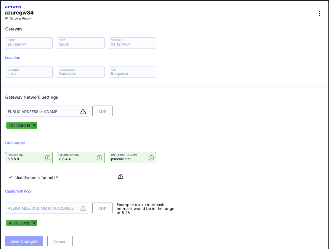
FIGURE 123 Editing a Gateway configuration
On this page, you can edit the following settings:
TABLE 2 Editable Gateway Network Settings¶ Setting
Description
Public Address or CNAME
The public IP address or CNAME at which clients can externally reach the Gateway instance. To learn more, see Configuring Networks in your Gateway Datacenter.
DNS Server
Contains settings relating to the Domain Name Service (DNS). Enter your Primary DNS and Secondary DNS IP addresses, and DNS Search Domain.
(vSphere Gateways only) Use Manual Settings
Allows you to manually configure IP address settings for your Gateway Internal, External, and (optional) Management interfaces. Deselect this option to instead use DHCP.
(vSphere and KVM Gateways only) Use Dynamic Tunnel IP
Allows you to assign a pool of IP addresses that are dynamically mapped to client sessions, such that user traffic from the Gateway to the application can be identified as originating from a specific client. Enter an IP address and subnet (in the range 8-28) in CIDR notation, then click Add. To learn more about , see Using Dynamic IP Addressing to Profile Client Traffic.
Update any required Gateway/Gateway Group details, then click Save Changes.
Troubleshooting Gateway Issues
The Troublshooting page provides tools that enable you to investigate issues that might be affecting your Gateway or preventing it from operating normally.
Note
Troubleshooting is available only for fully registered Gateways, and is not supported for Gateway Groups.
To view Gateway troubleshooting tools:
Log into the Controller as a Tenant Admin, see Logging in as a Tenant Administrator.
From the nZTA menu, click the Secure Access icon, then select Gateways > Gateway List.
The All Gateways page appears, showing the full list of Gateway Groups and standalone Gateways currently configured on the Controller.
Select the required Gateway or Gateway Group.
The Gateways Overview page appears for the selected Gateway/Gateway Group.
Click the Secure Access icon, then select Gateways > Troubleshooting.
The Gateway Troubleshooting page appears, showing troubleshooting tools and options for the selected Gateway/Gateway Group.
The page content is affected by your choice of task in the Select Troubleshooting Task drop-down menu:
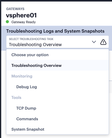
FIGURE 124 Viewing the list of available troubleshooting tasks for this Gateway
Choose from:
Troubleshooting Overview: a list of all captured data based on your completed troubleshooting activities.
Debug Log: make a trace recording of a selected process.
TCP Dump: observe and record TCP packets on the network.
Commands: run various common network troubleshooting commands.
System Snapshot: take a system snapshot.
Note
The availability of specific tasks is limited by Gateway version. Gateway instances based on versions earlier than 21.6 might have access only to a subset of this list.
Troubleshooting Overview
The Troubleshooting Overview contains a list of all captured data based on your completed troubleshooting activities. This shows:
TCP dumps
Debug logs
System snapshots
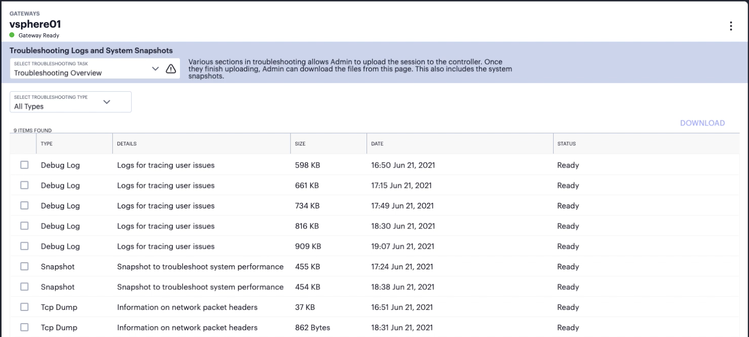
FIGURE 125 View a list of data files captured from previous troubleshooting activities
To filter the displayed files to a single type, use the Select Troubleshooting Type selector.
Debug Log
If your users are having difficulties getting access to a website or other resource, use the Debug Log task to make a trace recording for one or more selected processes running on the Gateway. This recording can then be uploaded to the Controller for offline analysis by Ivanti Technical Support.
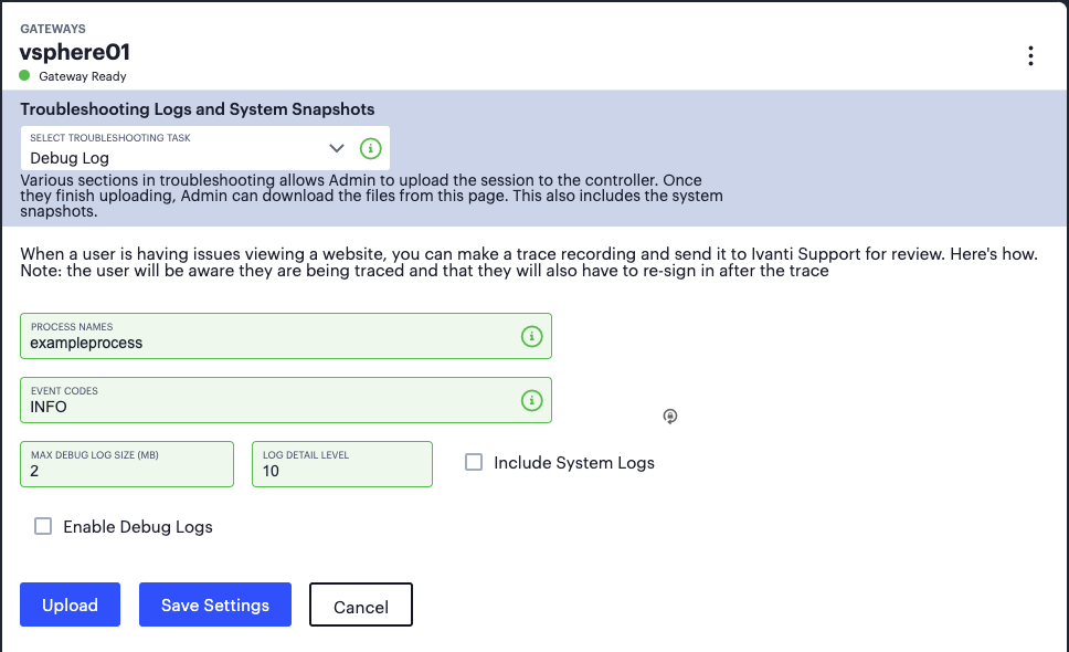
FIGURE 126 Recording a trace of a named process
Set the following fields:
Process Names: the names of one or more Gateway processes to trace
Event Codes: the event code, or codes, to observe in the trace. Only events matching these codes are appended to the log.
Max Debug Log Size (MB): The maximum allowable size, in MB, for the log file. Choose a value between 0-250.
Log Detail Level: The level of verbosity to include in the log. Choose a value between 0-60, from lowest to highest detail.
Include System Logs: Whether or not to include Gateway system logs (event, access, and admin logs) as part of the debug log.
To activate the trace, select Enable Debug Logs and then select Save Settings. To stop a running trace, deselect Enable Debug Logs and select Save Settings.
Note
Use Cancel to return the settings on this page to the state last saved.
After a trace has been captured, select Upload to upload the trace log file to the Controller.
TCP Dump
Use the TCP Dump task to inspect packet data passing through the network interfaces on your Gateway:

FIGURE 127 Inspecting TCP data packets
Select the network interfaces you want to inspect:
Internal or Virtual Port
External or Virtual Port
Management Port (where applicable)
Next, set the following optional fields as required:
Filter: A comma-separated filter expression for the TCP dump, based on standard UNIX TCP Dump filters. For more information, see https://www.freebsd.org/cgi/man.cgi?query=tcpdump.
The following table provides some examples:
TABLE 3 Example TCP dump filter expressions¶ Expression
Result
tcp port 80
Sniffs packets on TCP port 80
port 80
Sniffs packets on TCP or UDP port 80
ip
Sniffs the IP protocol
tcp
Sniffs the TCP protocol
dst #.#.#.#
Sniffs the destination IP address specified, where #.#.#.# is a valid IP address
src #.#.#.#
Sniffs the source IP address specified, where #.#.#.# is a valid IP address
port 80 or port 443
Sniffs on port 80 or port 443
src #.#.#.# and dst #.#.#.#
Sniffs the source and destination IP addresses or hosts specified, where each #.#.#.# represents a valid IP address
tcp port 80 or port 443 and dst #.#.#.# and src #.#.#.#
This example shows how to specify multiple parameters to create a filter that sniffs on TCP port 80, or on TCP or UDP port 443, and on the destination and source ports, where each #.#.#.# represents a valid IP address
Options: Command-line options to specify with the tcpdump. Use a space-separated list in the form “-<option>”. For more information on possible options, see https://www.freebsd.org/cgi/man.cgi?query=tcpdump.
Note
The following options are NOT supported: “-C”, “-B”, “-D”, “-G”, “-F”, “-V”, “-w”, “-W”, “-r”, “-E”, “-h”, “-I”, “-J”, “-L”, “-m”, “-p”, “-U”, “-z”, “-Z”, “-O”, NULL.
Promiscuous Mode: Enable or disable promiscuous mode for the data capture.
To start the TCP dump, select Start. Then, select Stop to end the process when required.
The current state is reflected in the Output window.
Note
Use Cancel to return the settings on this page to the state last saved.
After a TCP dump has been captured, select Upload to upload the log file to the Controller.
Commands
Use the Commands task to trigger common networking troubleshooting commands from the Gateway. For example, using the ping command:
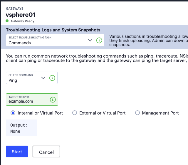
FIGURE 128 Running the Ping command
Use Select Command to select the command you want to run. Then, specify the parameters you want to use with that command.
To run the selected command with the specified parameters, select Start.
The command output is displayed in the Output window.
Note
Use Cancel to return the settings on this page to the state last saved.
The following table lists the available commands with parameters applicable in each case:
Command |
Parameter |
Description |
|---|---|---|
ping |
Target Server |
The target hostname or IP address |
Gateway Interface |
The network interface through which to capture the command output: internal, external, or management (where applicable) |
|
nslookup |
Query Type |
The nslookup query type you want to use: ANY, A, PTR, CNAME, MX, NS, SOA, TXT, UINFO, WKS |
Query |
The target IP address or FQDN. |
|
ARP |
Target Server |
The target hostname or IP address |
Gateway Interface |
The network interface through which to capture the command output: internal, external, or management (where applicable) |
|
Trace route |
Target Server |
The target hostname or IP address |
Gateway Interface |
The network interface through which to capture the command output: internal, external, or management (where applicable) |
|
Portprobe |
Target Server |
The target hostname or IP address |
Target Port |
Specify a valid port at the target server in the range 1-65535. |
|
Select Protocol |
Choose a protocol to use: TCP or UDP. |
|
Probe Count |
The number of probes to send. Use a value between 1-100. |
|
Probe Timeout |
The timeout value, in seconds, for each probe. Use a value between 1-180. |
System Snapshot
Use the System Snapshot task to trigger a snapshot of your Gateway system performance as it is currently configured:
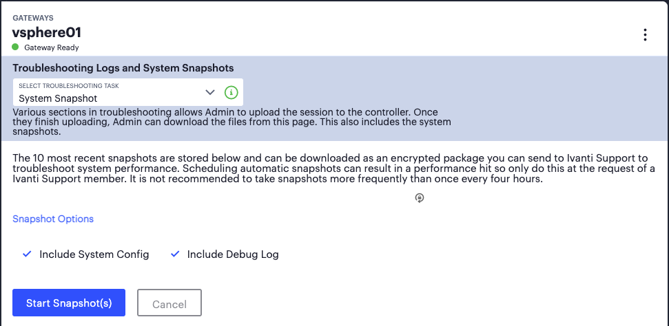
FIGURE 129 Taking a system snapshot
Note
Regular snapshots can result in a performance hit. Ivanti recommends not taking snapshots more frequently than once every four hours, unless at the request of a support representative.
Set the following fields:
Include System Config: Choose whether or not to include the system config with the snapshot. This includes information such as host name, cache entries on the gateway, the Controller it is connected to, and so on.
Include Debug Log: Choose whether or not to include the current debug log file with the snapshot.
Note
The current debug log is either created specifically by the admin through the Debug Log task, or in the absence of a created log, the default system debug log (generated automatically with Log level 0).
To capture the system snapshot, select Start Snapshot(s).
Note
Use Cancel to return the settings on this page to the state last saved.
Completed snapshots are automatically uploaded to the Troubleshooting Overview task page and can be downloaded as an encrypted package to send to Ivanti Technical Support to troubleshoot system performance.
Adding Gateway Groups for High Availability
nZTA uses Gateway Groups to implement high availability for your Gateway deployments. Grouping Gateways together ensures the Controller can synchronize out policy changes to all Gateways in a group, automatically. To learn more about high availability and how it can benefit your application delivery, see Using Gateway Groups for High Availability.
To learn more about the process of adding and registering individual Gateways with the Controller, see the following workflows:
To add a Gateway in VMware vSphere, see Workflow: Creating a Gateway in VMware vSphere.
To add a Gateway in Amazon Web Services (AWS), see Workflow: Creating a Gateway in Amazon Web Services.
To add a Gateway in Microsoft Azure, see Workflow: Creating a Gateway in Microsoft Azure.
To add a Gateway in KVM/OpenStack, see Workflow: Creating a Gateway in KVM/OpenStack.
To add a Gateway in Google Cloud Platform (GCP), see Workflow: Creating a Gateway in Google Cloud Platform.
After you have created your Gateways, you can add them to a Gateway Group. A Gateway already added a group cannot be added to a further Gateway Group, and cannot be used by more than one Secure Access Policy.
To add a Gateway Group:
Log into the Controller as a Tenant Admin, see Logging in as a Tenant Administrator.
From the nZTA menu, click the Secure Access icon, then select Manage Gateways > Gateway List.
The All Gateways page appears, showing the full list of Gateway Groups and standalone Gateways currently configured on the Controller.
To add a new Gateway Group, select Create from the top-right:
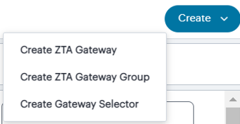
FIGURE 130 Add a new Gateway or Gateway Group
In the drop-down menu, click Create ZTA Gateway Group.
The Create ZTA Gateway Group dialog appears.
Enter a Name for the Gateway Group.
(Optional) Enter a Description for the Gateway Group.
Enter the Load Balancer IP addresses or CNAME. That is, a list of the public IP addresses or CNAMEs of the load balancer’s front-end interface that your end users connect to. Enter a value, then select Add to add it to the list. Repeat this step for each entry you want to add.
(Optional) Select the pre-existing Gateways you want to add to this group. Use the drop-down list to select a Gateway, then select Add. Repeat this step for each Gateway you want to add.
To add this Gateway Group, click Create Gateway Group.
A newly added Gateway Group appears on the All Gateways page alongside all ungrouped Gateways.
Note
For cloud-based Gateways: If you plan to add multiple deployed Gateways to a Gateway Group for high availability, additional configuration is required for the public IP addresses assigned to your instances. For more details, see Registering an Amazon Web Services Gateway (for AWS) or Creating a Gateway using the Azure Template and Image Files (for Azure).
Creating Gateway Selectors
The Gateway Selector feature provides optimal gateway selection and dynamic failover when deploying multiple geographically located nZTA gateways.
Tenant admins can select Gateways/Gateway Groups and set the priorities to identify to which set of Gateways the Client should connect to access the application. Tenant admins can then manually configure policies that determine to which Gateway an end-user is sent when they access an application.
To add a Gateway Selector:
Log into the Controller as a Tenant Admin, see Logging in as a Tenant Administrator.
From the nZTA menu, click the Secure Access icon, then select Manage Gateways > Gateway Selector.
The Gateways Selector List page appears.
To add a new Gateway Selector, select Create from the top-right:
FIGURE 131 Add a new Gateways Selector
In the drop-down menu, click Create Gateway Selector.
The Gateway Selector Details page appears.
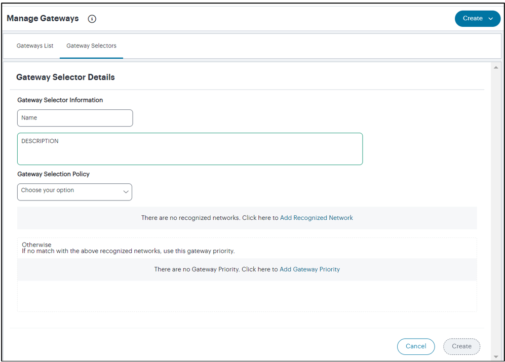
FIGURE 132 Gateway Selector Details
Enter a Name for the Gateway Selector.
(Optional) Enter a Description for the Gateway Selector.
In the Gateway Selector Policy section, you can choose or add Recognized Networks, and choose or add gateway priority.
To add a Recognized Network:
Click the Add Recognized Network link.
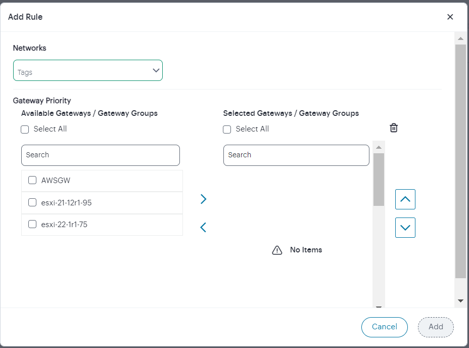
FIGURE 133 Add recognized network
In the Add Rule dialog, from the Networks drop-down list select a tag for the recognized network. To learn about creating tags, see the Associating Geographical locations to IP Addresses section in Using the Insights Menu to Monitor User Activity and Service Usage.
In the Gateway Priority section, select the gateways/gateway groups from the Available Gateways / Gateway Groups list.
Use the Up/Down arrows to change the priorities.
Click Add.
A newly added Recognized Network appears in the Gateway Selection Policy section.
To add Gateway Priority:
Click the Add Gateway Priority link.
The Gateway Priority window appears.

FIGURE 134 Set Gateway priority
Select the gateways/gateway groups from the Available Gateways / Gateway Groups list.
Use the Up/Down arrows to change the priorities.
Click Add.
A newly added Gateway Priority appears in the Gateway Selection Policy section.
In the Gateway Selector Details page, click Create.
A newly added Gateway Selector appears in the Gateway Selectors page.
To modify a Gateway Selector, click the adjacent three dots, then select Edit. In the Gateway Selector Details page, make the necessary changes and click Update.
To remove a Gateway Selector, click the adjacent three dots, then select Delete, and then confirm by clicking Delete.
Workflow: Creating a Gateway in VMware vSphere
The process of registering a vSphere Gateway with nZTA involves two main procedures, to be completed in sequence:
Create the Gateway record in the Controller.
Create the Gateway virtual machine instance in VMware vSphere.
After these steps have been completed successfully, the Controller and Gateway establish communication with each other.
Before you start, make sure that you have the following information and files for the Gateway:
An identifying name for the Gateway
The public IP address for the Gateway. This is the IP address at which clients can externally reach the Gateway instance.
The Gateway geographic location
(Optional) The name of the Gateway Group to which you want to add this new Gateway record. To learn more about Gateway Groups, see Adding Gateway Groups for High Availability.
The Gateway OVF template: https://pulsezta.blob.core.windows.net/gateway/ISA-V-VMWARE-ZTA-22.3R4-883.1.zip
Note
Download a copy of the OVF template archive file and unpack to a local workstation. Make sure the resulting file set is accessible from the vSphere Console.
Note
You can also choose to download this file from the Gateways Overview page in the nZTA Tenant Admin Portal. The opportunity to do this occurs later in this process.
Credentials for the vSphere Console.
Note
These credentials must include sufficient permissions to create a VM from a template image.
By default, nZTA derives Gateway DNS and network interface settings through DHCP (provided this is configured in your vSphere environment). If, instead, you want to manually specify your Gateway DNS and network interface settings, make sure you have the following additional information:
The internal/private subnet IP address, subnet mask, and network gateway IP address.
The primary (and optional secondary) DNS server IP address, and search domain.
The external interface IP address, subnet mask, and network gateway IP address.
(Optional) The management interface IP address, subnet mask, and network gateway IP address.
Note
If you choose to deploy a vSphere-based Gateway instance with DHCP configuration, DNS server settings are not configurable through the nZTA Tenant Admin UI. In this scenario, make sure you have at least a primary DNS server configured and available through DHCP (a secondary DNS server is optional). Make sure also that a DNS search domain is properly configured.
Adding a vSphere Gateway in the Controller
To register a Gateway on your Controller, use the Gateway Network Configuration dialog.
To begin, log into the Controller Tenant Admin Portal using the credentials provided in your welcome email. Two outcomes are possible:
On unconfigured nZTA systems, the Secure Access Setup Onboarding wizard appears (see Working with the Onboarding Wizard). In this case, click Add Gateway.
On configured nZTA systems, the Network Overview page appears. In this case:
From the nZTA menu, click the Secure Access icon, then select Gateways > Gateway List.
The Gateways List page appears, showing the full list of Gateway Groups and standalone Gateways currently configured on the Controller.
To add a new Gateway, select Create from the top-right:
FIGURE 135 Add a new Gateway or Gateway Group
In the drop-down menu, click Create ZTA Gateway.
In both cases, the Gateway Network Configuration dialog appears.
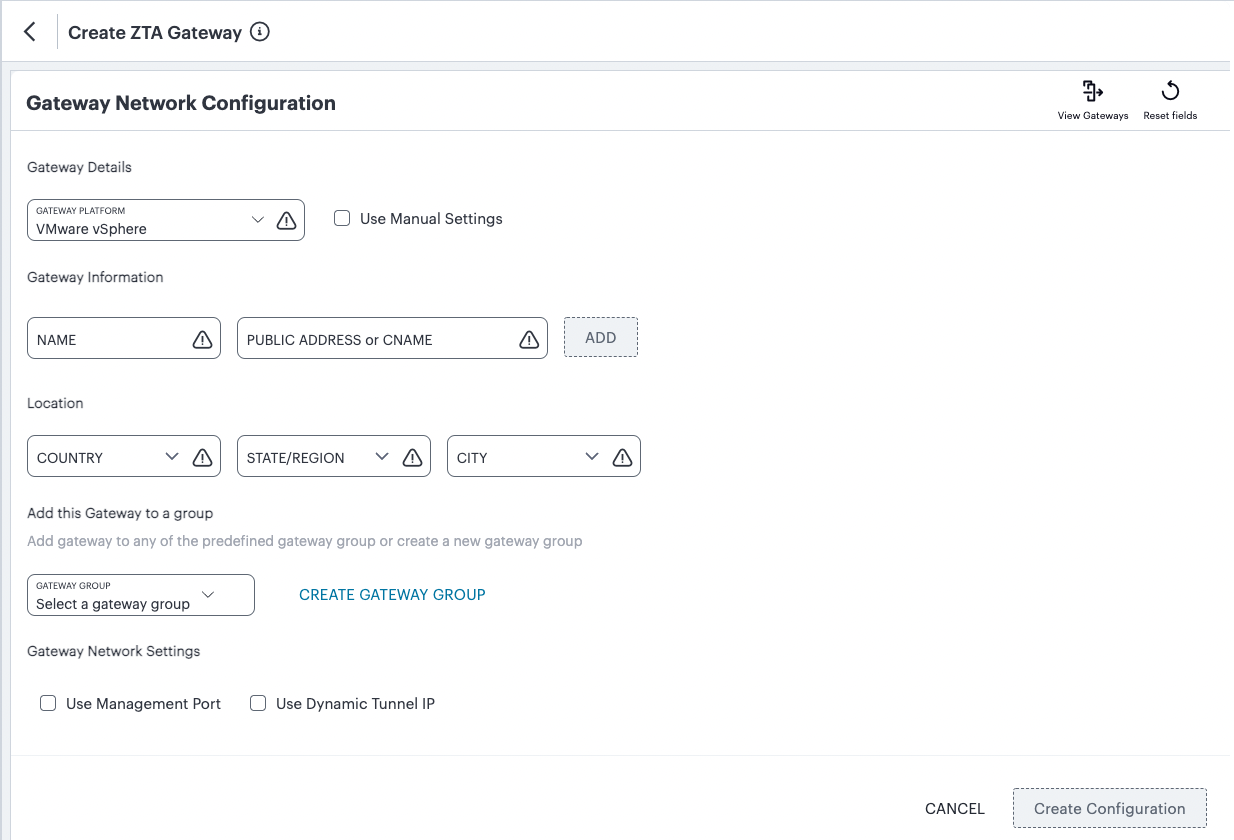
FIGURE 136 Gateway Network Configuration
Enter the following details:
For Gateway Platform, select “VMware vSphere”.
(Optional) To enter your vSphere Gateway instance DNS and network interface settings manually, select Use Manual Settings. To instead allow nZTA to use DHCP-derived settings for DNS and network interfaces, leave Use Manual Settings un-selected. To learn more about these settings, see Configuring Networks in your Gateway Datacenter.
Enter a Name for the Gateway.
Enter one or more Public Address or CNAME (Public IP address or CNAME) for the Gateway. Select Add to add each entry to the list. To learn more about this setting, see Configuring Networks in your Gateway Datacenter.
Select a geographic Location for the Gateway.
(Optional) Select a Gateway Group to which the new Gateway is to be added. To learn more about Gateway Groups, see Adding Gateway Groups for High Availability.
(Optional) Select the Use Management Port check box to use management network ports for nZTA traffic rather than internal ports.
Note
When the management port is enabled, Gateway will use management interface to communicate with Controller and NTP Server.
The Gateway will still use the internal port for DNS resolution and NTP server name resolution.
If the internal DNS cannot resolve the Controller domain, the internal interface will require internet access.
(Optional) Select the Use Dynamic Tunnel IP check box to configure a pool of IP addresses that are dynamically mapped to client sessions with this Gateway, such that user traffic from the Gateway to an application can be identified as originating from a specific client. To learn more, see Using Dynamic IP Addressing to Profile Client Traffic.
The Custom IP Pool dialog appears:
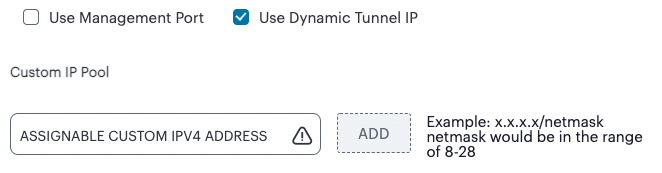
FIGURE 137 Gateway Network Configuration - Custom IP Pool settings
Note
Dynamic Tunnel IP addresses are not supported in Gateway Groups.
Use the Assignable Custom IPv4 Address field to enter an IP address and subnet (in the range 8-28) in CIDR notation, then click Add. Repeat this step for each address/subnet you want to use.
If you elected to use manual settings, the following panel appears:
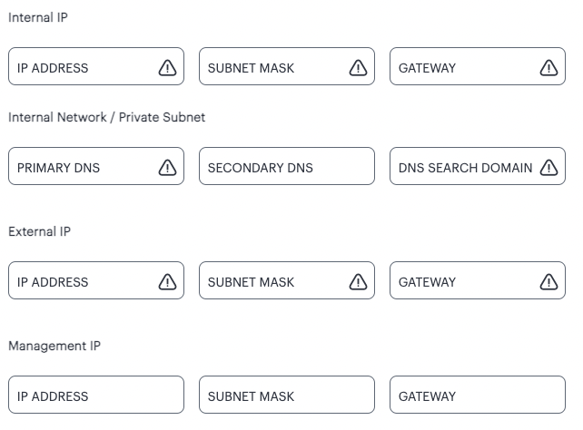
FIGURE 138 Gateway Network Configuration - manual settings
Enter the following details:
Specify the internal IP Address for the Gateway.
Specify the internal Subnet Mask for the Gateway.
Specify the internal network gateway IP address as the Gateway setting.
Enter the Primary DNS IP address for the Gateway.
(Optional) Enter the Secondary DNS IP address for the Gateway.
Enter the DNS Search Domain for the Gateway.
Specify the external IP Address for the Gateway.
Specify the external Subnet Mask for the Gateway.
Specify the external network gateway IP address as the Gateway setting.
Note
Management network settings are optional, unless the Use Management Port check box is selected.
Specify the management IP Address for the Gateway.
Specify the management Subnet Mask for the Gateway.
Specify the management network gateway IP address as the Gateway setting.
To add a Gateway definition based on the settings you specified in this dialog, select Create Configuration.
After you complete this process, an unregistered Gateway record is created on the Controller. You can view this Gateway record on the Gateways > Gateways List page.
Next, create the Gateway virtual machine instance in VMware vSphere and allow it to register with the Controller. This links the Gateway record on the Controller with the actual Gateway virtual machine, see Registering a VMware vSphere Gateway.
Registering a VMware vSphere Gateway
This section describes the steps necessary to create the Gateway virtual machine in the vSphere console. To learn more about the operations included here, refer to VMware’s own documentation for full details.
Note
For reference, the recommended minimum requirements for a Gateway virtual machine instance in vSphere are:
4 vCPU’s and 8 GB memory, or
8 vCPU’s and 32 GB memory
After you have created an unregistered Gateway record on the Gateways page, you must create the Gateway instance on the VMware vSphere Console. This process facilitates communication between the Controller and the Gateway instance.
Before you start, make sure you have obtained the Gateway definition file from the Controller. This definition file includes the settings necessary to configure the new Gateway virtual machine with the identity and location of the Controller, and is used during the registration process described later in this section.
To download the Gateway definition file:
Log into the Controller as a Tenant Admin, see Logging in as a Tenant Administrator.
From the nZTA menu, click the Secure Access icon, then select Gateways > Gateways List.
The Gateways List page appears.
Locate and select your unregistered vSphere Gateway record from the list of available Gateways.
Click the Download icon and select Download gateway init config to obtain a copy of the Gateway definition file.
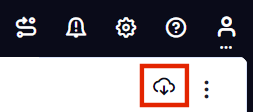
FIGURE 139 The Download Icon
Save the downloaded text file to a location accessible from the vSphere Console.
Note
The Gateway definition file is valid for 24 hours. If this period expires, you must replace the Gateway to generate a new Gateway definition file.
(Optional) If you have not yet downloaded the latest version of your Gateway VM file, click the Download icon and select Download gateway VM image. Save the archive file and unpack to a local workstation. Make sure the resulting file set is accessible from the vSphere Console.
To register a Gateway:
Access the vSphere console, either from a client or a web browser.
In the vSphere console, start the Deploy OVF Template wizard to create a new virtual machine based on the nZTA vSphere Gateway template.
In the wizard:
Choose to deploy from a local file.
Locate and upload your OVF/VMDK template files.
Provide an identifying name and location for the new Gateway virtual machine.
Choose any required compute resource.
Choose the required storage settings.
Customize the vApp properties of your virtual machine and, in the VA IVE Configuration parameter, paste the raw text of your Gateway definition file. To obtain the Gateway definition file, see the process described earlier in this section.
Confirm all settings.
Finish the wizard to create the Gateway VM.
Locate the new Gateway VM in the hosts and clusters.
Start the Gateway VM by powering it on.
Wait until the power-up is complete.
Return to the Gateways List page on the Controller.
Locate the new Gateway record in the list and confirm that its status has updated to Connected.
(Optional) After you have registered a Gateway, you can configure it (or the Gateway Group to which it belongs) as the default Gateway if required. A default Gateway handles all requests from applications that are not referenced by any secure access policy. See Configuring a Default Gateway for Application Discovery.
After this process completes, you can move to the next stage of nZTA configuration, which is Working with User Authentication.
Workflow: Creating a Gateway in Amazon Web Services
The process of registering an AWS Gateway with nZTA involves two main procedures, to be completed in sequence:
Create the Gateway record in the Controller.
Create the Gateway virtual machine instance in Amazon Web Services (AWS).
After these steps have been completed successfully, the Controller and Gateway establish communication with each other.
Before you start, make sure that you have the following information and files for the Gateway:
An identifying name for the Gateway
The public IP address for the Gateway. This is the IP address at which clients can externally reach the Gateway instance, typically an elastic IP address provided by AWS.
The Gateway geographic location.
(Optional) The name of the Gateway Group to which you want to add this new Gateway record. To learn more about Gateway Groups, see Adding Gateway Groups for High Availability.
The primary (and optional secondary) DNS server IP address, and search domain.
The Gateway template file. ZTA Gateways can be deployed in a new VPC or an existing VPC, using the Nitro hypervisor. Select the JSON template file that is applicable to your requirements:
To deploy in an existing VPC - Nitro hypervisor (M5-type instances):
https://pulsezta.blob.core.windows.net/gateway/templates/AWS/23-2-883/Nitro/ivanti-zta-2-nics-existing-vpc.json
https://pulsezta.blob.core.windows.net/gateway/templates/AWS/23-2-883/Nitro/ivanti-zta-3-nics-existing-vpc.jsonTo deploy in a new VPC - Nitro hypervisor (M5-type instances):
https://pulsezta.blob.core.windows.net/gateway/templates/AWS/23-2-883/Nitro/ivanti-zta-2-nics-new-network.json
https://pulsezta.blob.core.windows.net/gateway/templates/AWS/23-2-883/Nitro/ivanti-zta-3-nics-new-network.json
Note
If you want to use a Management interface, you must download and use the 3 NIC template.
Note
You might not be able to specify the download location given here directly to AWS. In this case, download the Gateway template file first to your local workstation and specify this location instead.
Note
You can also choose to download this file from the Gateways Overview page of the nZTA Tenant Admin Portal. The opportunity to do this occurs later in this process.
The Gateway AMI identifier. nZTA gateway AMIs are available in all AWS regions (except China).
In most cases, after the Gateway image becomes available in the AWS Marketplace, the AMI applicable to your region is automatically selected. Alternatively, to perform a manual search, follow these steps:
Log into the AWS console.
Navigate to EC2 > Images > AMIs.
Select “Public Images”.
Search for the image corresponding to your selected hypervisor:
Nitro: “ISA-V-NITRO-ZTA-22.3R4-883.1-SERIAL-nitro.img”
Make a note of the corresponding AMI ID.
Credentials for the AWS Management Console.
Note
These credentials must include sufficient permissions to create a stack.
The SSH key pair file that you are using with the AWS Management Console.
Adding an AWS Gateway in nSA
To registering a Gateway on your Controller, use the Gateway Network Configuration dialog.
To begin, log into the Controller Tenant Admin Portal using the credentials provided in your welcome email. Two outcomes are possible:
On unconfigured nZTA systems, the Secure Access Setup Onboarding wizard appears (see Working with the Onboarding Wizard). In this case, click Add Gateway.
On configured nZTA systems, the Network Overview page appears. In this case:
From the nZTA menu, click the Secure Access icon, then select Gateways > Gateway List.
The Gateways List page appears, showing the full list of Gateway Groups and standalone Gateways currently configured on the Controller.
To add a new Gateway, select Create from the top-right:
FIGURE 140 Add a new Gateway or Gateway Group
In the drop-down menu, click Create ZTA Gateway.
In both cases, the Gateway Network Configuration dialog appears.

FIGURE 141 Gateway Network Configuration
Enter the following details:
For Gateway Platform, select “Amazon Web Services”.
Enter a Name for the Gateway.
Enter one or more Public Address or CNAME (Public IP address or CNAME) for the Gateway. Select Add to add each entry to the list. To learn more about this setting, see Configuring Networks in your Gateway Datacenter.
Select a geographic Location for the Gateway.
(Optional) Select a Gateway Group to which the new Gateway is to be added. To learn more about Gateway Groups, see Adding Gateway Groups for High Availability.
(Optional) Select the Use Management Port check box to use management network ports for nZTA traffic rather than internal ports.
Note
When the management port is enabled, Gateway will use management interface to communicate with Controller and NTP Server.
The Gateway will still use the internal port for DNS resolution and NTP server name resolution.
If the internal DNS cannot resolve the Controller domain, the internal interface will require internet access.
Enter the Primary DNS IP address for the Gateway.
(Optional) Enter the Secondary DNS IP address for the Gateway.
Enter the DNS Search Domain for the Gateway.
Note
Make sure the specified DNS service can resolve the IP address of your Controller. Issues here can cause registration of the Gateway with the Controller to fail.
To add a Gateway definition based on the settings you specified in this dialog, select Create Configuration.
After you complete the first part of this workflow, an unregistered Gateway record is created on the Controller. This Gateway record can be seen on the Gateways > Gateways List page.
Next, create the Gateway virtual machine instance on AWS and allow it to register with the Controller. This links the Gateway record on the Controller with the actual Gateway virtual machine, see Registering an Amazon Web Services Gateway.
Registering an Amazon Web Services Gateway
This section describes the steps necessary to create the Gateway virtual machine in the AWS management console. To learn more about the operations included here, refer to Amazon’s own documentation for full details.
After you have created an unregistered Gateway record on the Gateways page, you must create the Gateway instance on the AWS Management Console. This process facilitates communication between the Controller and the Gateway instance.
Before you start, make sure you have obtained the Gateway definition file from the Controller. This definition file includes the settings necessary to configure the new Gateway virtual machine with the identity and location of the Controller.
To download the Gateway definition file:
Log into the Controller as a Tenant Admin, see Logging in as a Tenant Administrator.
From the nZTA menu, click the Secure Access icon, then select Gateways > Gateways List.
The Gateways List page appears.
Locate and select your unregistered AWS Gateway record from the list of available Gateways.
Click the Download icon to obtain a copy of the Gateway definition file.
FIGURE 142 The Download Icon
Save the downloaded text file to a location accessible from the AWS Management Console.
Note
The Gateway definition file is valid for 24 hours. If this period expires, you must replace the Gateway to generate a new Gateway definition file.
(Optional) If you have not yet downloaded the latest version of your Gateway VM file, click the Download icon and select Download gateway VM image. Save the archive file and unpack to a local workstation. Make sure the resulting file set is accessible from the AWS Management Console.
To register a Gateway:
Access the AWS Management Console and log in using your credentials.
In the AWS Services menu, select CloudFormation.
The CloudFormation home page appears.
Click Create Stack and then, from the sub-menu, select With new resources (standard).
The Specify template step of the Create Stack wizard appears.
Under Prerequisite - prepare template, select the Template is ready option.
Under Specify Template, select the Upload a template file template source option.
Under Upload a template file, click Choose File and select the Gateway template file that you downloaded at the start of this process.
The file uploads, and the AWS S3 URL for the uploaded template file appears automatically.
Click Next.
The Specify stack details step of the Create Stack wizard appears. This page displays the details and parameters required by the Gateway template.
Enter a Stack name.
Specify the parameters as appropriate for your deployment:
If you are deploying the Gateway instance into a new VPC, you can accept the default values used for all parameters.
If you are deploying the instance into an existing VPC, you must manually specify the details of your existing VPC into the parameters on the page. For more information, contact Ivanti Technical Support.
Under ZTA Gateway Configuration, identify the Gateway AMI using its ZTA Gateway AMI ID. Choose the designated AMI for the region in which you are deploying the Gateway instance.
For Instance Type, select the instance type that fits your hypervisor choice ( Nitro) and minimum requirements, based on the following recommended types:
Note
For reference, the recommended minimum requirements for a Gateway virtual machine instance in AWS are:
For Nitro hypervisor-based instances, use M5 types:
m5.large (2 vCPU, 8 GB Memory) (2NIC min)
m5.xlarge (4 vCPU, 16 GB Memory) (3NIC min)
m5.2xlarge (8 vCPU, 32 GB Memory)
m5.4xlarge (16 vCPU, 64 GB Memory)
For ZTA Gateway Config Data, paste in the raw text of your Gateway definition file. To obtain the Gateway definition file, see the process described earlier in this section.
For SSH Key Name, specify your existing SSH key pair name.
For Load Balancer Configuration, If you plan to deploy multiple Gateways inside a Gateway Group, select “Yes” to deploy a new internet-facing network load balancer instance alongside the Gateway. Select “No” to launch only this Gateway instance.
Note
This option is applicable only for new VPC templates.
If you elect to launch a load balancer, the following pre-configuration is applied:
An Elastic IP address is assigned to the load balancer.
A TCP listener is configured on port 443.
An IP-based Target Group is created and the private IP address of the deployed Gateway’s external network interface is added as a target.
A health-check is configured on TCP port 443.
Stickiness is enabled on the Target Group.
After you have deployed the Gateway and Load Balancer, you must return to the Tenant Admin Portal on the Controller and update the Gateway Group Load Balancer IP ADDRESS setting to be the Load Balancer’s public IP address.
If you want to configure the Load Balancer to balance across further Gateway instances from the Gateway Group, you must deploy each subsequent Gateway into an existing VPC and then update the Load Balancer Target Group.
Note
With new VPC templates, a NAT gateway is deployed for routing outbound Internet traffic from the Gateway’s internal network interface in order for the Gateway to be able to reach the Controller.
Note
Public IP addresses are not automatically assigned to any of your Gateway’s network interfaces. If you are deploying a Gateway into an existing VPC, in order for the Gateway to be able to reach the Controller from it’s internal network interface, make sure you allow outbound Internet traffic from the Private Subnet for the deployed Gateway.
To learn more about high availability and Gateway Groups, see Adding Gateway Groups for High Availability and Using Gateway Groups for High Availability.
Click Next.
The Configure stack options step of the Create Stack wizard appears. All properties that were specified either in the template or in earlier steps are populated automatically.
No changes or new inputs are required.
Click Next.
The Review step of the Create Stack wizard appears.
Confirm all displayed details.
Click Create stack.
The Stacks page appears. The new stack is listed using the Stack name you specified during the wizard. The new stack has a status of CREATE_IN_PROGRESS.
Wait for the status of the new stack to reach CREATE_COMPLETE.
(This step is required only if you have not deployed your Gateway with a Load Balancer or NAT at the front-end) Elastic IP addresses are not automatically assigned to any of the Gateway’s network interfaces. Therefore, before you can access the new Gateway instance from the Controller, you must associate a new Public IP address with the external interface of the Gateway. Then, return to the Controller Tenant Admin Portal and update the Gateway Public IP Address setting to match this address.
In the Tenant Admin Portal Secure Access > Gateways > Gateways List page, make sure the new Gateway has a confirmed status of Connected.
Note
You can directly access your AWS instance over SSH using AWS EC2 Instance Connect. To configure AWS EC2 Instance Connect, refer to the Amazon Web Service Documentation. You can then connect to the instance directly as a serial console using SSH from inside the AWS Management Console, refer to the Amazon Web Service Documentation.
(Optional) After you have registered a Gateway, you can configure it (or the Gateway Group to which it belongs) as the default Gateway if required. A default Gateway handles all requests from applications that are not referenced by any secure access policy. See Configuring a Default Gateway for Application Discovery.
After this process completes, you can move to the next stage of nZTA configuration, which is Working with User Authentication.
Workflow: Creating a Gateway in Microsoft Azure
The process of registering an Azure Gateway with nZTA involves two main procedures, to be completed in sequence:
Create a Gateway record in the Controller.
Create a Gateway virtual machine instance in Azure and register it with the Controller.
Azure offers two methods for launching a Gateway virtual machine instance:
Through the Azure Marketplace
Using the provided template and image files
Before you start, make sure that you have the following information and files for the Gateway:
An identifying name for the Gateway
The Gateway geographic location.
(Optional) The name of the Gateway Group to which you want to add this new Gateway record. To learn more about Gateway Groups, see Adding Gateway Groups for High Availability.
The primary (and optional secondary) DNS server IP address, and search domain.
The SSH public key that you are using with the Azure Portal or Management Console.
Note
SSH keys can be generated using sshkeygen on Linux and macOS, or PuTTyGen on Windows. For further details about generating SSH key pairs, see:
* For Windows: https://docs.microsoft.com/en-us/azure/virtual-machines/linux/ssh-from-windows
* For MacOS and Linux: https://docs.microsoft.com/en-us/azure/virtual-machines/linux/mac-create-ssh-keysCredentials for the Azure Portal or Management Console.
Note
These credentials must include sufficient permissions to create a virtual machine.
Additionally, if you are deploying a Gateway instance directly from the template and image files (as opposed to using the Azure Marketplace):
The Gateway template JSON file:
Note
ZTA Gateways can be deployed in a new VNET or an existing VNET. Select the JSON template file applicable to your requirements.
To deploy in a new VNET:
https://pulsezta.blob.core.windows.net/gateway/templates/Azure/23-2-883/ivanti-zta-2-nics.json
https://pulsezta.blob.core.windows.net/gateway/templates/Azure/23-2-883/ivanti-zta-3-nics.jsonTo deploy in an existing VNET:
https://pulsezta.blob.core.windows.net/gateway/templates/Azure/23-2-883/ivanti-zta-2-nics-existing-vnet.json
https://pulsezta.blob.core.windows.net/gateway/templates/Azure/23-2-883/ivanti-zta-3-nics-existing-vnet.json
Note
If you want to use a Management interface, you must download and use the 3 NIC template.
The Gateway template image VHD file. Choose from:
Americas: https://pulsezta.blob.core.windows.net/gateway/ISA-V-HYPERV-ZTA-22.3R4-883.1-SERIAL-hyperv.vhd
APJ: https://pulseztaapj1.blob.core.windows.net/gateway/ISA-V-HYPERV-ZTA-22.3R4-883.1-SERIAL-hyperv.vhd
Europe: https://pulseztaeurope.blob.core.windows.net/gateway/ISA-V-HYPERV-ZTA-22.3R4-883.1-SERIAL-hyperv.vhd
Use the link most suitable for your geographic location.
Note
Registering an Azure Gateway in the Controller can also choose to download this file from the Gateways Overview page of the nZTA Tenant Admin Portal. The opportunity to do this occurs later in this process.
A public IP address or CNAME for the Gateway. This is the IP address or CNAME at which client devices can externally reach the Gateway instance.
Note
CNAMEs are not currently supported on Ivanti Secure Access Client Linux variants.
Adding an Azure Gateway in nSA
To registering a Gateway on your Controller, use the Gateway Network Configuration dialog.
To begin, log into the Controller Tenant Admin Portal using the credentials provided in your welcome email. Two outcomes are possible:
On unconfigured nZTA systems, the Secure Access Setup Onboarding wizard appears (see Working with the Onboarding Wizard). In this case, click Add Gateway.
On configured nZTA systems, the Network Overview page appears. In this case:
From the nZTA menu, click the Secure Access icon, then select Gateways > Gateway List.
The Gateways List page appears, showing the full list of Gateway Groups and standalone Gateways currently configured on the Controller.
To add a new Gateway, select Create from the top-right:
FIGURE 143 Add a new Gateway or Gateway Group
In the drop-down menu, click Create ZTA Gateway.
In both cases, the Gateway Network Configuration dialog appears.

FIGURE 144 Gateway Network Configuration
Enter the following details:
For Gateway Platform, select “Azure”.
Enter a Name for the Gateway.
Enter one or more Public Address or CNAME (Public IP address or CNAME) for the Gateway. Select Add to add each entry to the list. To learn more about this setting, see Configuring Networks in your Gateway Datacenter.
Note
For Azure Marketplace deployments, a public IP address or CNAME is typically allocated at deployment time through the Azure Portal. Therefore, if you do not yet know the expected address/CNAME, enter a dummy value in this field now and update the setting after you have deployed and registered the Gateway instance. For more details on this process, see Creating a Gateway through Azure Marketplace.
Select a geographic Location for the Gateway.
(Optional) Select a Gateway Group to which the new Gateway is to be added. To learn more about Gateway Groups, see Adding Gateway Groups for High Availability.
(Optional) Select the Use Management Port check box to use management network ports for nZTA traffic rather than internal ports.
Note
When the management port is enabled, Gateway will use management interface to communicate with Controller and NTP Server.
The Gateway will still use the internal port for DNS resolution and NTP server name resolution.
If the internal DNS cannot resolve the Controller domain, the internal interface will require internet access.
Enter the Primary DNS IP address for the Gateway.
(Optional) Enter the Secondary DNS IP address for the Gateway.
Enter the DNS Search Domain for the Gateway.
Note
Make sure the specified DNS service can resolve the IP address of your Controller. Issues here can cause registration of the Gateway with the Controller to fail.
To add a Gateway definition based on the settings you specified in this dialog, select Create Configuration.
After you complete the first part of this workflow, an unregistered Gateway record is created on the Controller. This Gateway record can be seen on the Gateways > Gateways List page.
Next, create the Gateway virtual machine instance on Azure and allow it to register with the Controller. This links the Gateway record on the Controller with the actual Gateway virtual machine. Choose to register the Gateway instance through the Azure Marketplace (see Creating a Gateway through Azure Marketplace) or through the Azure management console (see Creating a Gateway using the Azure Template and Image Files).
Creating a Gateway through Azure Marketplace
This section describes the steps necessary to create the Gateway virtual machine in Microsoft Azure by using the Azure Marketplace. To learn more about the operations included here, refer also to Microsoft’s own Azure documentation (https://docs.microsoft.com/azure) for full details.
After you have created an unregistered Gateway record on the Gateways page, you must create the Gateway instance in the Azure portal. This process facilitates communication between the Controller and the Gateway instance.
Before you start, you must obtain the Gateway definition file from the Controller. This definition file includes the settings necessary to configure the new Gateway virtual machine with the identity and location of the Controller.
To download the Gateway definition file:
Log into the Controller as a Tenant Admin, see Logging in as a Tenant Administrator.
From the nZTA menu, click the Secure Access icon, then select Gateways > Gateways List.
The Gateways List page appears.
Locate and select your unregistered Azure Gateway record from the list of available Gateways.
Click the Download icon to obtain a copy of the Gateway definition file.
FIGURE 145 The Download Icon
Save the downloaded text file to a location accessible from the Microsoft Azure Portal.
Note
The Gateway definition file is valid for 24 hours. If this period expires, you must replace the Gateway to generate a new Gateway definition file.
(Optional) If you have not yet downloaded the latest version of your Gateway VM file, click the Download icon and select Download gateway VM image. Save the archive file and unpack to a local workstation. Make sure the resulting file set is accessible from the Microsoft Azure Portal.
To create a Gateway instance from Azure Marketplace:
Note
ZTA Gateways in Azure Marketplace are limited to version 21.3R1 at the present time. To use a Gateway version later than 21.3R1, either launch the Azure Marketplace version and upgrade in-place to the latest version (see Upgrading Gateways) or use the alternate procedure described in Creating a Gateway using the Azure Template and Image Files to launch a Gateway instance using the template and image files.
Log into the Microsoft Azure Portal (https://portal.azure.com).
Navigate to the Azure Marketplace by clicking Create a resource.
In the Search the Marketplace text box, enter “Ivanti”.
Azure Marketplace presents the results relevant to your search term.
Locate Ivanti Neurons Zero Trust Access Gateway and click Create.
In the drop-down list, choose the option that is applicable to your needs:
Ivanti Neurons Zero Trust Access Gateway - BYOL 3 NIC: Includes 3 network interfaces (internal, external, and management)
Ivanti Neurons Zero Trust Access Gateway - BYOL 2 NIC: Includes 2 network interfaces (internal and external)
Note
To first learn more about Ivanti Neurons Zero Trust Access Gateway, click the product banner and view the associated information page. You can launch a new Gateway instance from this page.
The Create Ivanti Neurons Zero Trust Access Gateway process appears.
On the Basics tab, enter the following details:
Subscription: If you are using the “PZT_Dev” subscription, leave this field as the default value. Otherwise, enter your subscription name.
Resource Group: Specify the resource group in which the Gateway needs to be deployed, or create a new resource group using the link provided. An Azure Resource Group is a container for a collection of connected assets that you assign to a virtual machine. To learn more, see the Azure documentation (https://docs.microsoft.com/azure).
Region: Specify the geographic region in which the Gateway instance is deployed.
Ivanti Neurons Zero Trust Access Gateway VM Name: Enter a suitable name for your Gateway instance. This name must be 1-9 characters long, using only lowercase letters or numbers.
SSH Public Key Source: Select “Use existing public key”.
SSH Public Key: Copy and paste an RSA public key in a single-line format or the multi-line PEM format.
Note
SSH keys can be generated using sshkeygen on Linux and macOS, or PuTTyGen on Windows. For further details about generating SSH key pairs, see:
* For Windows: https://docs.microsoft.com/en-us/azure/virtual-machines/linux/ssh-from-windows
* For MacOS and Linux: https://docs.microsoft.com/en-us/azure/virtual-machines/linux/mac-create-ssh-keysTo continue, click Next: Network Settings >.
On the Network Settings page, enter the following details:
Virtual Network: A virtual network is a logical isolation of the Azure cloud dedicated to your services. The value you enter here affects the IP address and subnet allocations for all network interfaces shown on this page. Azure pre-populates this field with a new virtual network name, although you can select your own predefined virtual network as necessary.
To create a new virtual network, perform the following steps:
Click the Create New link under the Virtual Network setting.
The Create virtual network dialog appears.
Enter a virtual network name.
Enter an address space in CIDR notation (for example, 192.0.2.0/24).
For each interface subnet, use the automatically-populated name and address values provided, or enter your own details. Each subnet must be contained by the address space entered in the previous setting.
To save your changes, click OK.
Your new virtual network settings are populated into the corresponding interface settings in the main Network Settings page.
Internal Subnet: The subnet identifier for the Internal network, pre-populated by either the selected Virtual Network or your newly-entered virtual network settings.
External Subnet: The subnet identifier for the External network, pre-populated by either the selected Virtual Network or your newly-entered virtual network settings.
(For 3 NIC instances only) Management Subnet: The subnet for the Management network, pre-populated by either the selected Virtual Network or your newly-entered virtual network settings.
Public IP for Ivanti Neurons Zero Trust Access Gateway external interface LB: The public IP address identifier at which clients can externally reach the Gateway instance, typically provided by Azure.
Note
Before you can connect to the new Gateway instance from the Controller, you must update the Controller with the Public IP address or CNAME assigned to the external interface of the Gateway load balancer. This process is described later.
DNS prefix for external interface LB: The unique DNS name for the public IP address specified for the external interface load balancer.
Public IP for NAT Gateway: The public IP address identifier of a NAT Gateway for the virtual machine to communicate with the Controller and other public resources.
DNS prefix for NAT Gateway public IP: The unique DNS name for the public IP address specified for the internal interface NAT Gateway.
Deploy Ivanti Neurons Zero Trust Access Gateway with Load Balancer: To deploy this Gateway with a load balancer, select “Yes” from the drop-down list. The front-end IP address of the load balancer is then used as the public IP address for your Gateway.
Note
If you select “No” to not deploy a load balancer, you must create and associate a public IP address to the external interface of your instance after deployment is complete.
In all cases, on completion of this process, you must update the Controller Gateway definition with the correct public IP address for your Azure Gateway instance.
To continue, click Next: Instance Configuration >.
On the Instance Configuration page, enter the following details:
Ivanti Neurons Zero Trust Access Gateway VM Size: This is the specification of the virtual machine. Choose from:
For 2nic instances, select “1 x Standard DS2 v2”
For 3nic instances, select “1 x Standard DS4 v2”
Diagnostic storage account: The storage account for the virtual machine diagnostics. The default value is a new account based on your VM name.
Ivanti Neurons Zero Trust Access Gateway Version: Specify the version applicable to the current nZTA version, or the version you require. Ivanti recommends you select the latest available version.
Ivanti Neurons Zero Trust Access Gateway Config Data: Paste in the raw text of your Gateway definition file. To obtain the Gateway definition file, see the process described earlier in this section.
To continue, click Next: Review + create >.
On the Review + create page, verify the proposed configuration is validated successfully, and then click Create to create your new Gateway instance.
After a short wait, your instance is created and deployed.
Access the virtual machine settings for your new Gateway instance, and click Networking from the Settings menu.
The Networking dialog appears, showing your attached network interfaces (internal, external, and (optionally) management).
Click the tab that corresponds to the external network interface.
The settings for the external network interface appear.
Locate the NIC Public IP field and make a note of the IP address shown there. This is the public IP address you use to reconfigure the Controller record for this Gateway.
If no public IP address is shown, determine if a load balancer was deployed together with your Gateway instance by selecting the Load balancing tab.
If a load balancer was deployed, make a note of the Frontend IP address displayed in this tab and use this as the Gateway public IP address on the Controller.
If a load balancer was not deployed, create a public IP address and associate it with the external interface. Then, use this IP address as the Gateway public IP address on the Controller.
Note
To learn about configuring IP addresses in the Azure portal, see the Microsoft Azure documentation.
Return to the nZTA Tenant Admin Portal, and click Secure Access > Gateways > Gateways List.
The All Gateways page appears.
Select your new Azure Gateway from the list.
The Gateways Overview page appears.
Make sure the new Azure Gateway instance is shown in the list of configured Gateways and is connected (Status is Online and State is Registered).
Select Secure Access > Gateways > Configuration, and locate Gateway Network Settings. Enter the Public IP address you noted from the Azure virtual machine settings. Make sure you remove any previously-entered dummy values.
To save your changes, click Save Changes.
This completes the Azure Gateway registration process. Your enrolled client devices should now be able to connect to the Gateway.
You can view all Gateways that are deployed in your nZTA service (see Viewing and Monitoring Gateways in the Controller) or you can move to the next stage of nZTA configuration, which is Working with User Authentication.
Creating a Gateway using the Azure Template and Image Files
This section describes the steps necessary to create the Gateway virtual machine in Microsoft Azure by using the provided template and image files. To learn more about the operations included here, refer also to Microsoft’s own Azure documentation for full details.
After you have created an unregistered Gateway record on the Gateways page, you must create the Gateway instance in the Azure Management Console. This process facilitates communication between the Controller and the Gateway instance.
Before you start, you must complete the following prerequisites:
Obtain the Gateway definition file from the Controller. This definition file includes the settings necessary to configure the new Gateway virtual machine with the identity and location of the Controller.
To download the Gateway definition file:
Log into the Controller as a Tenant Admin, see Logging in as a Tenant Administrator.
From the nZTA menu, click the Secure Access icon, then select Gateways > Gateways List.
The Gateways List page appears.
Locate and select your unregistered Azure Gateway record from the list of available Gateways.
Click the Download icon to obtain a copy of the Gateway definition file.
FIGURE 146 The Download Icon
Save the downloaded text file to a location accessible from the Microsoft Azure Console.
Note
The Gateway definition file is valid for 24 hours. If this period expires, you must replace the Gateway to generate a new Gateway definition file.
(Optional) If you have not yet downloaded the latest version of your Gateway VM file, click the Download icon and select Download gateway VM image. Save the archive file and unpack to a local workstation. Make sure the resulting file set is accessible from the Microsoft Azure Portal.
Create a new Azure Resource Group in your desired location and subscription account.
Create a new storage account, and create a new container in that account.
Download the nZTA Azure VHD image file for your region and copy it to the storage account you created in the previous step.
Choose to download from the following regions:
Americas: https://pulsezta.blob.core.windows.net/gateway/ISA-V-HYPERV-ZTA-22.3R4-883.1-SERIAL-hyperv.vhd
APJ: https://pulseztaapj1.blob.core.windows.net/gateway/ISA-V-HYPERV-ZTA-22.3R4-883.1-SERIAL-hyperv.vhd
Europe: https://pulseztaeurope.blob.core.windows.net/gateway/ISA-V-HYPERV-ZTA-22.3R4-883.1-SERIAL-hyperv.vhd
For this process, you can use azcopy:
From the storage account, create a Shared Access Signature (SAS) token:

FIGURE 147 Creating a SAS token from a storage account in Azure
Open the Azure Cloud Shell and start a bash shell:
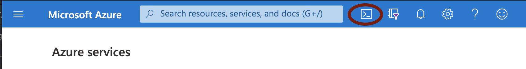
FIGURE 148 Starting the Azure Cloud Shell
In the Azure Cloud shell, use azcopy to copy the Gateway VHD image file into your storage account. For example, use the following syntax:
azcopy copy '<URL to VHD file>' 'https://<MyStorageAccount>.blob.core.windows.net/<Container_Name>/<VHD filename><SAS-Token>''
Replace the angled-bracket elements with the details gathered in previous steps. For example:
azcopy copy 'https://pulseztaeurope.blob.core.windows.net/gateway/PSA-V-HYPERV-ZTA-189.1-SERIAL-hyperv.vhd' 'https://MyStorage.blob.core.windows.net/gateway/PSA-V-HYPERV-ZTA-189.1-SERIAL-hyperv.vhd?sv=2018-11-12&ss=bfqt&srt=co&sp=rwdlacupx&se=2019-12-29T02:57:39Z&st=2020-07-28T18:57:39Z&spr=https&sig=mJU7WNd9oNY7wcXNOqEOhbYshD9Sxv56rqEl%2FmEuCg4%3D'
To create a Gateway instance using the template and image files specified in the release notes for this product version:
Note
For reference, the recommended minimum requirements for a Gateway virtual machine instance in Azure are:
Standard_D2s_v3 (2 vCPU, 8 GB Memory), or
Standard_F4s (4 vCPU, 8 GB Memory)
Access the Azure Management Console and log in using your credentials.
Access the Home > Templates page to view available templates.
Click “+ Add” to add a new template.
In the new template “General” section, enter a template name and description.
In the new template “ARM Template” section, remove the default data and replace with the raw text contents of the nZTA Azure Gateway template JSON file.
Note
Use either the new VNET template JSON file or the existing VNET template JSON file as per your requirements.
Save the new template.
On the Home > Templates page, locate the new Azure Gateway template.
On the context menu for the template, click Deploy.
The Custom Deployment page appears.
On the Custom Deployment page, enter any required details for the Gateway deployment.
Resource Group: Specify the resource group name in which the Gateway needs to be deployed, or create a new group.
Location: Specify the region in which the Gateway instance is deployed.
ZTA Storage Account Name: Specify the storage account you created earlier where the Gateway image is held.
ZTA Storage Account Resource Group: Specify the resource group you created earlier.
ZTA Image Location URI: Enter the full URI for the Gateway template image VHD file you copied to your storage account earlier.
ZTA VM Name: Enter a suitable name for your Gateway instance. Ivanti recommends matching the Gateway name used during the process of creating the Gateway record on the Controller.
ZTA Config: Paste in the raw text of your Gateway definition file. To obtain the Gateway definition file, see the process described earlier in this section.
SSH Public Key: Specify your SSH key pair name.
If required, update the labels for the instance:
Update the Dns Label Prefix Ext if required. For example, “azuregwext”.
Update the Dns Label Prefix Mgmt if required. For example, “azuregwmgmt”.
Update the Existing Vnet Name if required.
Update the Existing Internal Subnet if required. For example: “InternalNW”.
Update the Existing External Subnet if required. For example: “ExternalNW”.
Update the Existing Management Subnet if required. For example: “ManagementNW”.
For Load Balancer Configuration, If you plan to deploy multiple Gateways inside a Gateway Group, select “Yes” to deploy a new internet-facing Public Standard Load Balancer instance alongside the Gateway. Select “No” to launch only this Gateway instance.
Note
This option is applicable only for new VNET templates.
If you elect to launch a load balancer, the following pre-configuration is applied:
A Standard SKU Public IP address is assigned to the Load Balancer.
A Backend Pool is created and the deployed Gateway is associated with the pool through it’s external network interface.
A health probe is configured on TCP port 443.
Load balancing rules are configured.
After you have deployed the Gateway and Load Balancer, you must return to the Tenant Admin Portal on the Controller and update the Gateway Group Load Balancer IP ADDRESS setting to be the Load Balancer’s public IP address.
If you want to configure the Load Balancer to balance across further Gateway instances from the Gateway Group, you must deploy each subsequent Gateway into the same Resource Group through the use of existing VNET templates and then update the Load Balancer’s Backend Pool.
Note
With new VNET templates, a NAT gateway is deployed for routing outbound Internet traffic from the Gateway’s internal network interface in order for the Gateway to be able to reach the Controller.
Note
Public IP addresses are not automatically assigned to any of your Gateway’s network interfaces. If you are deploying a Gateway into an existing VNET, in order for the Gateway to be able to reach the Controller from it’s internal network interface, make sure you allow outbound Internet traffic from the Private Subnet for the deployed Gateway.
To learn more about high availability and Gateway Groups, see Adding Gateway Groups for High Availability and Using Gateway Groups for High Availability.
Agree to the terms and conditions.
Click Purchase to start the creation of the Gateway.
A window displays the status of the process, starting with Deployment in Progress.
(Optional) Click the Deployment in Process hyperlink to view a status page for the process.
Wait until the process completes.
Ensure that your Azure Security Groups support the IP addresses allocated to the Gateway instance. Please refer to Azure’s own documentation for full details.
(This step is required only if you have not deployed your Gateway with a Load Balancer or NAT at the front-end) Public IP addresses are not automatically assigned to any of the Gateway’s network interfaces. Therefore, before your client devices can connect to the new Gateway instance from the Controller, you must associate a new Public IP address with the external interface of the Gateway. Then, update the Controller’s Gateway Public IP address setting to match this address (in the Secure Access > Gateways > Gateways List page, select your new Gateway, then select Secure Access > Gateways > Configuration and locate Gateway Network Settings).
In the Secure Access > Gateways > Gateways List page, make sure the new Gateway has a confirmed status of Connected.
This completes the Azure Gateway registration process. Your enrolled client devices should now be able to connect to the Gateway.
(Optional) After you have registered a Gateway, you can configure it (or the Gateway Group to which it belongs) as the default Gateway if required. A default Gateway handles all requests from applications that are not referenced by any secure access policy. See Configuring a Default Gateway for Application Discovery.
You can view all Gateways that are deployed in your nZTA service (see Viewing and Monitoring Gateways in the Controller) or you can move to the next stage of nZTA configuration, which is Working with User Authentication.
Workflow: Creating a Gateway in KVM/OpenStack
This workflow leads you through the processes for setting up a KVM Gateway in OpenStack. These processes must be performed in sequence:
Preparing to create a KVM gateway, see Preparing to Create a KVM Gateway.
Creating the gateway record in the Controller, see Adding a KVM Gateway in nSA.
Preparing Metadata for OpenStack, see Preparing Metadata for OpenStack.
Creating the KVM Gateway virtual machine instance in OpenStack, see Creating the KVM Gateway Virtual Machine Instance in OpenStack.
After these steps have been completed successfully, the Controller and Gateway establish communication with each other.
Preparing to Create a KVM Gateway
Before you start, make sure you have the following information and files:
An identifying name for the Gateway
The public IP address for the Gateway. This is the IP address at which clients can externally reach the Gateway instance.
The Gateway geographic location
(Optional) The name of the Gateway Group to which you want to add this new Gateway record. To learn more about Gateway Groups, see the Tenant Admin Guide.
Additionally, to manually specify KVM Gateway network interface settings:
The primary (and optional secondary) DNS server IP address, and search domain.
The required internal/private subnetworks must already be defined on OpenStack. Please refer to the OpenStack documentation for details.
The required external subnetworks must already be defined on OpenStack. Please refer to the OpenStack documentation for details.
(Optional) Any required management subnetwork must already be defined on OpenStack. Please refer to the OpenStack documentation for details.
The Gateway KVM template: https://pulsezta.blob.core.windows.net/gateway/ISA-V-KVM-ZTA-22.3R4-883.1.zip
Note
Download a copy of the KVM template ZIP file. Then fully unpack the ZIP file, including any compressed .gz files inside, to a local workstation. Make sure that the resulting file set is accessible from the OpenStack Console.
Note
You can also choose to download this file from the Gateways Overview page of the nZTA Tenant Admin Portal. The opportunity to do this occurs later in this process.
Credentials for the OpenStack Console.
Note
These credentials must include sufficient permissions to create a virtual machine from a template image.
After you have all required information, you can set up a nZTA KVM gateway, see Adding a KVM Gateway in nSA.
Adding a KVM Gateway in nSA
To registering a Gateway on your Controller, use the Gateway Network Configuration dialog.
To begin, log into the Controller Tenant Admin Portal using the credentials provided in your welcome email. Two outcomes are possible:
On unconfigured nZTA systems, the Secure Access Setup Onboarding wizard appears (see Working with the Onboarding Wizard). In this case, click Add Gateway.
On configured nZTA systems, the Network Overview page appears. In this case:
From the nZTA menu, click the Secure Access icon, then select Gateways > Gateway List.
The Gateways List page appears, showing the full list of Gateway Groups and standalone Gateways currently configured on the Controller.
To add a new Gateway, select Create from the top-right:
FIGURE 149 Add a new Gateway or Gateway Group
In the drop-down menu, click Create ZTA Gateway.
In both cases, the Gateway Network Configuration dialog appears.
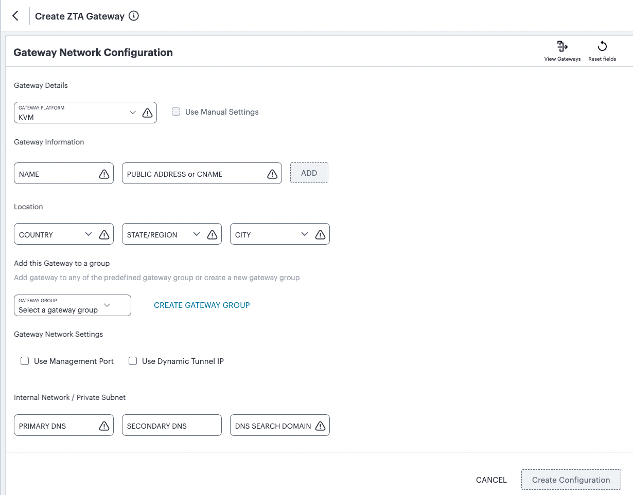
FIGURE 150 Gateway Network Configuration
Enter the following details:
For Gateway Platform, select “KVM”.
Enter a Name for the Gateway.
Enter one or more Public Address or CNAME (Public IP address or CNAME) for the Gateway. Select Add to add each entry to the list. To learn more about this setting, see Configuring Networks in your Gateway Datacenter.
Select a geographic Location for the Gateway.
(Optional) Select a Gateway Group to which the new Gateway is to be added. To learn more about Gateway Groups, see Adding Gateway Groups for High Availability.
(Optional) Select the Use Management Port check box to use management network ports for nZTA traffic rather than internal ports.
Note
When the management port is enabled, Gateway will use management interface to communicate with Controller and NTP Server.
The Gateway will still use the internal port for DNS resolution and NTP server name resolution.
If the internal DNS cannot resolve the Controller domain, the internal interface will require internet access.
(Optional) Select the Use Dynamic Tunnel IP check box to configure a pool of IP addresses that are dynamically mapped to client sessions with this Gateway, such that user traffic from the Gateway to an application can be identified as originating from a specific client. To learn more, see Using Dynamic IP Addressing to Profile Client Traffic.
The Custom IP Pool dialog appears:
FIGURE 151 Gateway Network Configuration - Custom IP Pool settings
Note
Dynamic Tunnel IP addresses are not supported in Gateway Groups.
Use the Assignable Custom IPv4 Address field to enter an IP address and subnet (in the range 8-28) in CIDR notation, then click Add. Repeat this step for each address/subnet you want to use.
Enter the Primary DNS IP address for the Gateway.
(Optional) Enter the Secondary DNS IP address for the Gateway.
Enter the DNS Search Domain for the Gateway.
Note
Make sure the specified DNS service can resolve the IP address of your Controller. Issues here can cause registration of the Gateway with the Controller to fail.
To add a Gateway definition based on the settings you specified in this dialog, select Create Configuration.
After you complete the first part of this workflow, an unregistered Gateway record is created on the Controller. This Gateway record can be seen on the Gateways > Gateways List page.
You can now prepare your metadata, see see Preparing Metadata for OpenStack.
Preparing Metadata for OpenStack
The preparation of metadata for use on OpenStack currently requires some manual steps:
Log into the Controller as a Tenant Admin, see Logging in as a Tenant Administrator.
From the nZTA menu, click the Secure Access icon, then select Gateways > Gateways List.
The Gateways List page appears, showing the full list of Gateway Groups and standalone Gateways currently configured on the Controller.
locate and select your KVM Gateway.
The Gateways Overview page appears.
Click the Download icon to obtain a copy of the Gateway definition file.
FIGURE 152 The Download Icon
Specify a save location for your Gateway definition file.
Note
The Gateway definition file is valid for 24 hours. If this period expires, you must replace the Gateway to generate a new Gateway definition file.
(Optional) If you have not yet downloaded the latest version of your Gateway VM file, click the Download icon and select Download gateway VM image. Save the archive file and unpack to a local workstation. Make sure the resulting file set is accessible from the OpenStack Management Portal.
View the gateway definition file in a text editor.
Start a separate text editor file, and paste the following template text block into it:
<pulse-config>
   <config-download-url>
      '<insert vaConfigURL value here>'
   </config-download-url>
   <appliance-id>
      <insert vaApplianceID value here>
   <secondary-dns>
      <insert vaSecondaryDNS here>
   </secondary-dns>
   <primary-dns>
      <insert vaPrimaryDNS here>
   </primary-dns>
   <dns-domain>
      <insert vaDnsSearchDomain here>
   </dns-domain>
   </appliance-id>
   <cert-common-name>
      <insert vaCommonName value here>
   </cert-common-name>
   <accept-license-agreement>
      y
   </accept-license-agreement>
   <controller-enrolled-hostname>
      <insert va|CTR_name|EnrolledHostname value here>
   </controller-enrolled-hostname>
   <dns-search-domain>
      <insert vaDnsSearchDomain value here>
   </dns-search-domain>
   <controller-hostname>
      <insert va|CTR_name|Hostname value here>
   </controller-hostname>
</pulse-config>
For each parameter block in the template text block file:
Locate the required metadata property for the line.
For example, in the following block:
<appliance-id>
   <insert vaApplianceID value here>
</appliance-id>
You require the vaApplianceID value from the gateway definitions file.
Locate the required value in the gateway definitions file.
For example, the vaApplianceID value is 99ce3aa3c9494cbabb51c085c9c3f6ad.
Copy and paste this value from the gateway definitions file into the template text file.
For example, the <appliance-id> block will now read as follows:
<appliance-id>
   99ce3aa3c9494cbabb51c085c9c3f6ad
</appliance-id>
Note
You do not need to change the <accept-license-agreement> block, and can retain its y setting.
After you have added all required text to the template text file, save that file for use in the next section.
You can now create a KVM gateway VM in Openstack, see Creating the KVM Gateway Virtual Machine Instance in OpenStack.
Creating the KVM Gateway Virtual Machine Instance in OpenStack
To create a KVM VM instance in OpenStack:
Access the OpenStack Management Portal, either from a client or a web browser, and log in using your OpenStack credentials.
In the OpenStack console, the Overview page appears.
In the left menu, click Compute > Images.
The Images page appears. This shows a list of images.
Above the list of images, click Create Image.
The Create Image wizard appears. In this wizard, you upload a KVM gateway image for use.
Under Image Details:
Enter an Image Name. Typically, this incorporates a version number. For example, ZTA_GWY_100.
Enter an Image Description. For example: ZTA KVM Image.
Under Image Source, click Browse and select the unpacked KVM disc image file. Then, click Format and select QCOW2 - QEMU Emulator.
Under Image Requirements, set Minimum Disk (GB) to 40 and Minimum RAM (KB) to 2048.
Set Visibility Setting as required. Public will enable the image to be used in other projects. Private will not.
Set Image Sharing as required.
Use the default settings for all other properties.
Click Next.
The Metadata page of the wizard appears. No action is required on this page, all properties can use their default settings.
Click Create Image.
The wizard closes, and the new KVM gateway image is added to the Images page.
Wait until the image has been uploaded and processed and shows as Active.
Note
The upload image process typically takes 15-20 minutes.
After the image has uploaded and is Active, click its Launch button.
The first page of the Launch Instance wizard appears. In this wizard, you create a KVM gateway instance.
Under Details:
Enter an Instance Name. This will be the displayed name of the gateway in nZTA.
Enter a Description for the KVM gateway. For example ZTA KVM Gateway.
Use the default settings for all other properties.
Click Next.
The Source page of the wizard appears. This page lists the selected disk image and selected/default settings for the instance. No action is required on this page, all properties can use their displayed settings.
Click Next.
The Flavor page of the wizard appears. This page lists the available types of gateway you can create.
Locate the PSA3000-V entry and click its “up arrow” button to select it.
Click Next.
The Networks page of the wizard appears. This page lists the available networks (and associated subnetworks) for the gateway. It enables you to select the required subnetworks for your gateway.
In the available list, locate the required subnetworks.
For example, you may require a subnetwork for internal ports and a subnetwork for external ports, but not a subnetwork for management interfaces.
Note
If the required subnetworks do not yet exist, you must define them. Please refer to the OpenStack documentation for details of this process.
Click the “up arrow” button for each subnetwork to select it.
Note
For each selected subnetwork, a fixed IP address is added automatically to the gateway. These appear later in this process, so that they can be assigned to floating IP addresses.
Click Next.
The Network Ports page of the wizard appears. No action is required on this page, all properties can use their displayed settings.
Click Next.
The Security Groups page of the wizard appears. No action is required on this page, all properties can use their displayed settings.
Note
If there is no default security group defined, you must define one. Please refer to the OpenStack documentation for details of this process.
Click Next.
The Key Pair page of the wizard appears. No action is required on this page, all properties can use their displayed settings.
Click Next.
The Configuration page of the wizard appears. This page enables you to configure the gateway instance using metadata you prepared earlier, see Preparing Metadata for OpenStack.
Open your template text file and copy the entire text block that starts with
<pulse-config>and ends with</pulse-config>.Paste the text block into the Customization Script block.
Note
You cannot directly paste metadata for your gateway from nZTA. You must prepare a suitable text block from the metadata, see Preparing Metadata for OpenStack.
Enable the Configuration Drive check box.
Click Launch Instance.
The wizard closes, and the new KVM gateway instance is added.
Access the Instances page.
The new KVM gateway instance is listed on this page.
Wait until the Power State of the gateway instance is Running.
Note
This process may take several minutes.
After the instance state changes to Running, make a note of the subnetworks and their automatically-assigned fixed IP addresses in the IP Address column for the instance. For example:
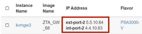
FIGURE 153 Unassociated KVM Ports
In this example, floating IP addresses are listed after the fixed IP addresses, so all are unassociated:
The fixed IP address on the int-port-2 subnetwork is 4.4.10.83.
The fixed IP address on the ext-port-2 subnetwork is 5.5.10.64.
Access the Network > Floating IPs page.
The Floating IPs page shows the floating IP addresses associated with your account. Both associated and unassociated floating IP addresses are listed.
Note
Associated floating IPs have a Mapped Fixed IP Address listed.
Identify an unassociated floating IP address that you want to associate with a fixed IP address.
Click the Associate button for the fixed IP address.
The Manage Floating IP Associations dialog appears.
Select a fixed port to be associated for the selected floating IP address.
Click Associate to conform the association.
Repeat the association process until each of the fixed IP addresses for your gateway instance is associated with a floating IP address.
Wait until the status of these floating IP addresses all show as Active.
Return to the Compute > Instances page.
This page now shows a fixed IP address associated with floating IP address for each port. For example:
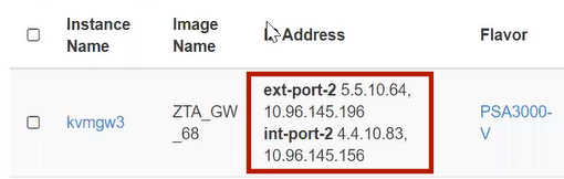
FIGURE 154 Associated KVM Ports
Click the Console tab.
A console monitor view shows the ongoing boot-up process for the instance.
Wait until the instance shows a screen similar to the following:
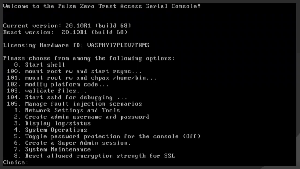
FIGURE 155 KVM Instance Console Monitor
Return to the Gateways List page on the Controller.
Locate the new Gateway record in the list and confirm that its status has updated to Connected. For example:

FIGURE 156 KVM Gateway Connected
(Optional) After you have registered a Gateway, you can configure it (or the Gateway Group to which it belongs) as the default Gateway if required. A default Gateway handles all requests from applications that are not referenced by any secure access policy. See Configuring a Default Gateway for Application Discovery.
Workflow: Creating a Gateway in Google Cloud Platform
This workflow leads you through the processes for setting up a Gateway on the Google Cloud Platform (GCP). These processes must be performed in sequence:
Preparing to create a GCP gateway, see Preparing to Create a GCP Gateway.
Creating the gateway record in the Controller, see Adding a GCP Gateway in nSA.
Downloading Metadata for Google Cloud Platform, see Downloading Metadata for Google Cloud Platform.
Uploading the GCP Image onto the Google Cloud Platform, see Uploading the GCP Virtual Machine Image onto the Google Cloud Platform.
Creating a VM Instance of the GCP image. Either:
Creating a VM Instance of the Uploaded GCP Image Manually, see Creating a VM Instance of the Uploaded GCP Image Manually.
Creating a VM Instance of the Uploaded GCP Image Using a Script/Template, see Creating a VM Instance of the Uploaded GCP Image Using a Script/Template.
Completing the Configuration of the Controller, see Completing the Configuration of the Controller.
After these steps have been completed successfully, the Controller and Gateway establish communication with each other.
Preparing to Create a GCP Gateway
Before you start, make sure you have the following information and files:
An identifying name for the Gateway.
The public IP address for the Gateway. This is the IP address at which clients can externally reach the Gateway instance, such as an LB/NAT or Datacenter network forward rules.
Note
If you want Google Cloud platform to allocated a public IP address automatically, you can use a dummy IP address (for example, 1.1.1.1) when you create the Gateway on nZTA. You must then update the Controller with the allocated public IP address afterwards.
The Gateway geographic location.
(Optional) The name of the Gateway Group to which you want to add this new Gateway record. To learn more about Gateway Groups, see the Tenant Admin Guide.
Note
A Gateway Group may have a defined public IP address, which you can specify during the creation of the Gateway.
The ZTA Gateway GCP virtual machine image: https://pulsezta.blob.core.windows.net/gateway/ISA-V-GCP-ZTA-22.3R4-883.1.tar.gz
Download a copy of the GCP Gateway image as a compressed TAR archive file, then decompress the archive to a local workstation. Make sure that the resulting file set is accessible from the Google Cloud Platform Console.
Note
You can also choose to download the Gateway image through the Gateways Overview page of the Controller after you have defined the Gateway record. The opportunity to do this occurs later in this process.
(Optional) GCP Gateway YAML templates, suitable for automating the creation of your GCP VM instances. Choose from:
To deploy in an existing VPC:
https://pulsezta.blob.core.windows.net/gateway/templates/GCP/23-2-883/ivanti-zta-2-nics-existing-vpc.zip
https://pulsezta.blob.core.windows.net/gateway/templates/GCP/23-2-883/ivanti-zta-3-nics-existing-vpc.zipTo deploy in a new VPC:
https://pulsezta.blob.core.windows.net/gateway/templates/GCP/23-2-883/ivanti-zta-2-nics-new-vpc.zip
https://pulsezta.blob.core.windows.net/gateway/templates/GCP/23-2-883/ivanti-zta-3-nics-new-vpc.zip
Note
You can also choose to download Gateway templates through the Gateways Overview page of the Controller after you have defined the Gateway record. The opportunity to do this occurs later in this process.
Credentials for the Google Cloud Platform Console.
Note
These credentials must include sufficient permissions to create a virtual machine from a template image.
Additionally, to manually specify GCP Gateway network interface settings:
The primary (and optional secondary) DNS server IP address, and search domain.
The required internal/private subnetworks must already be defined on Google Cloud Platform, including firewall settings. All required firewall settings for this interface are shown below.
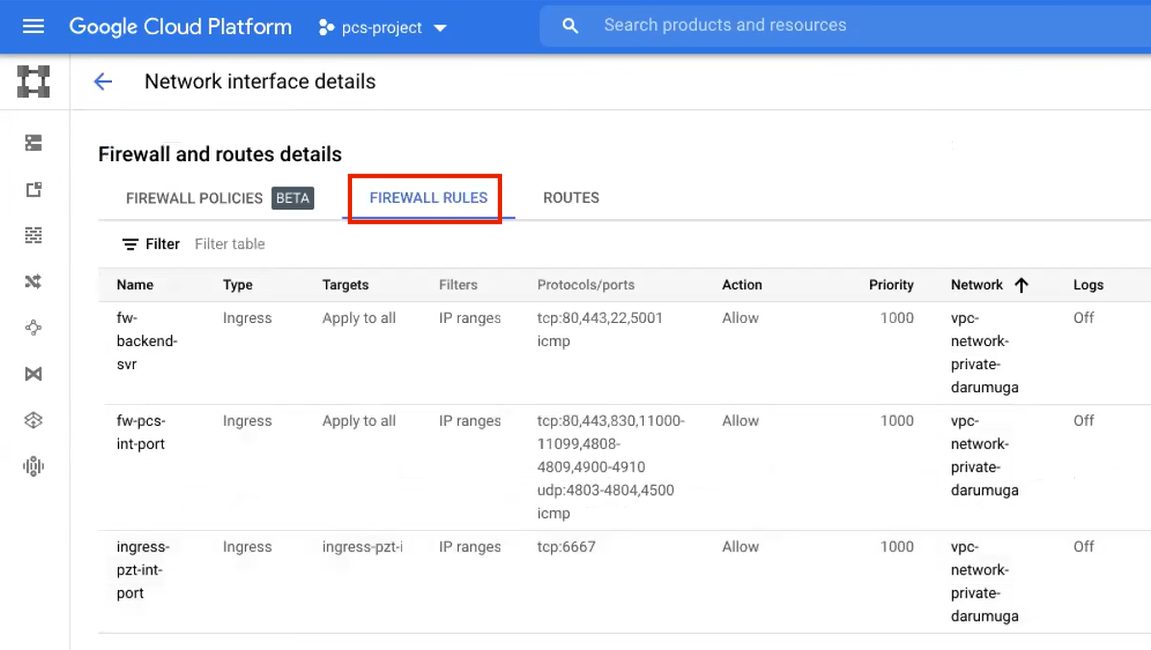
FIGURE 157 Internal/Private Firewall Rules
Refer to the Google Cloud Platform documentation for details.
The required external/public subnetworks must already be defined on Google Cloud Platform, including firewall settings. All required firewall settings for this interface are shown below.
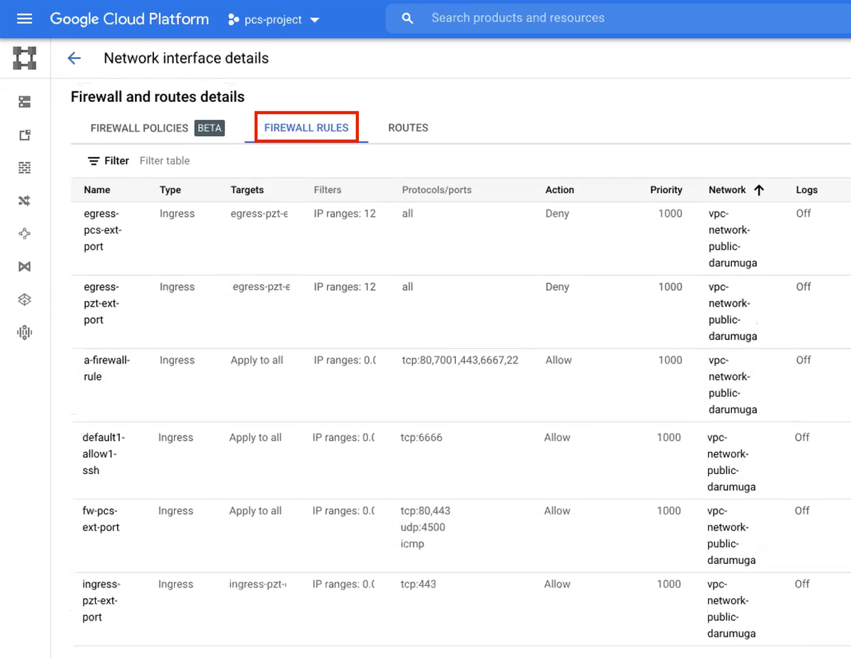
FIGURE 158 External/Public Firewall Rules
Refer to the Google Cloud Platform documentation for details.
(Optional) Any required management subnetwork must already be defined on Google Cloud Platform, including firewall settings. All required firewall settings for this interface are shown below.
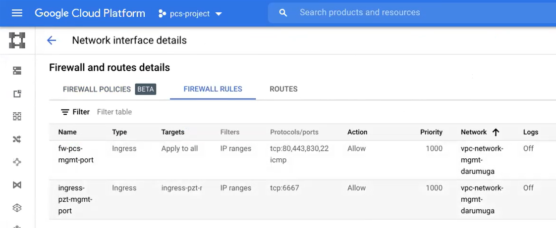
FIGURE 159 Management Firewall Rules
Refer to the Google Cloud Platform documentation for details.
After you have all required information, you can set up a nZTA GCP gateway, see Adding a GCP Gateway in nSA.
Adding a GCP Gateway in nSA
To registering a Gateway on your Controller, use the Gateway Network Configuration dialog.
To begin, log into the Controller Tenant Admin Portal using the credentials provided in your welcome email. Two outcomes are possible:
On unconfigured nZTA systems, the Secure Access Setup Onboarding wizard appears (see Working with the Onboarding Wizard). In this case, click Add Gateway.
On configured nZTA systems, the Network Overview page appears. In this case:
From the nZTA menu, click the Secure Access icon, then select Gateways > Gateway List.
The Gateways List page appears, showing the full list of Gateway Groups and standalone Gateways currently configured on the Controller.
To add a new Gateway, select Create from the top-right:
FIGURE 160 Add a new Gateway or Gateway Group
In the drop-down menu, click Create ZTA Gateway.
In both cases, the Gateway Network Configuration dialog appears.
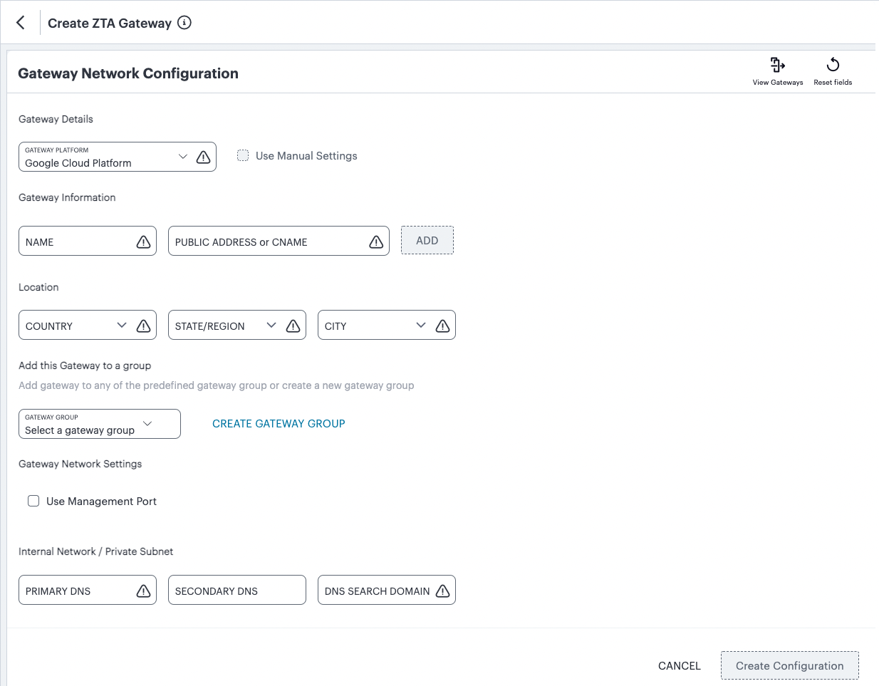
FIGURE 161 Gateway Network Configuration
Enter the following details:
For Gateway Platform, select “Google Cloud Platform”.
Enter a Name for the Gateway.
Enter one or more Public Address or CNAME (Public IP address or CNAME) for the Gateway. Select Add to add each entry to the list. To learn more about this setting, see Configuring Networks in your Gateway Datacenter.
Note
If you want Google Cloud Platform to allocate a public IP address automatically, you can use a dummy IP address (for example, 1.1.1.1) at this point. You must then update the Controller with the allocated public IP address after the GCP VM instance is created, see Completing the Configuration of the Controller.
Select a geographic Location for the Gateway.
(Optional) Select a Gateway Group to which the new Gateway is to be added. To learn more about Gateway Groups, see Adding Gateway Groups for High Availability.
Note
A Gateway Group may have a defined public IP address, which you can specify as the Public Address, see above.
(Optional) Select the Use Management Port check box to use management network ports for nZTA traffic rather than internal ports.
Note
When the management port is enabled, Gateway will use management interface to communicate with Controller and NTP Server.
The Gateway will still use the internal port for DNS resolution and NTP server name resolution.
If the internal DNS cannot resolve the Controller domain, the internal interface will require internet access.
Enter the Primary DNS IP address for the Gateway.
(Optional) Enter the Secondary DNS IP address for the Gateway.
Enter the DNS Search Domain for the Gateway.
Note
Make sure the specified DNS service can resolve the IP address of your Controller. Issues here can cause registration of the Gateway with the Controller to fail.
To add a Gateway definition based on the settings you specified in this dialog, select Create Configuration.
You can now download your metadata, see Downloading Metadata for Google Cloud Platform.
Downloading Metadata for Google Cloud Platform
The preparation of metadata for use on Google Cloud Platform currently requires some manual steps:
Log into the Controller as a Tenant Admin, see Logging in as a Tenant Administrator.
From the nZTA menu, click the Secure Access icon, then select Gateways > Gateways List.
The Gateways List page appears, showing the full list of Gateway Groups and standalone Gateways currently configured on the Controller.
Locate and select your GCP Gateway.
The Gateways Overview page appears.
Click the Download icon, then choose Download gateway init config to obtain a copy of the Gateway definition file.
FIGURE 162 The Download Icon
Specify a save location for your Gateway definition file.
Note
The Gateway definition file is valid for 24 hours. If this period expires, you must replace the Gateway to generate a new Gateway definition file.
(Optional) If you have not yet downloaded the latest version of your Gateway VM image and optional YAML templates, click the Download icon and select Download gateway VM image. Save the archive file and unpack to a local workstation. Make sure the resulting file set is accessible from the Google Cloud Platform Management Portal.
You can now create a GCP gateway VM in Google Cloud Platform, see Uploading the GCP Virtual Machine Image onto the Google Cloud Platform.
Uploading the GCP Virtual Machine Image onto the Google Cloud Platform
To upload a GCP Gateway virtual machine image into Google Cloud Platform:
Access the Google Cloud Platform Management Portal, either from a client or a web browser, and log in using your Google Cloud Platform credentials.
In the Google Cloud Platform console, select your required project from the pull-down list on the title bar. For example:

FIGURE 163 GCP Select Project
Click the Navigation menu, and then select Cloud Storage > Browser.
A list of GCP storage buckets appears.
Select the bucket into which you wish to place the GCP image.
A page listing the current contents of the bucket appears.
(Optional) Navigate to the required folder within the bucket.
Click Upload Files. For example:
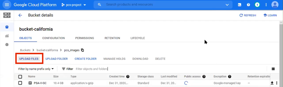
FIGURE 164 GCP Upload Files
An upload dialog appears.
Select the ZTA Gateway GCP virtual machine image .tar file from your local workstation (see Preparing to Create a GCP Gateway), and click Open.
Note
If you want to use the provided YAML templates to automate the creation of your VM instance (see Creating a VM Instance of the Uploaded GCP Image Using a Script/Template), select these in addition to the image archive.
The image archive and any selected template files are added to the bucket.
Wait until the upload completes. This may take several minutes.
Start a command line session from the title bar. For example:

FIGURE 165 GCP Upload Files
A command line session starts.
Navigate to the project folder.
Create an image from the ZTA Gateway image archive using the following command:
gcloud compute images create <instance_name> --source-uri=gs://<bucket_name>/<optional_path>/<image_name>.tar --guest-os-features MULTI_IP_SUBNET
For example:
gcloud compute images create ztagcp152 --source-uri=gs://bucket-california/pcs_images/PSA-V-GCP-ZTA-153.1-SERIAL-gcp.tar --guest-os-features MULTI_IP_SUBNET
You can now create a VM instance of the uploaded GCP image. To do this, either:
Perform the task manually, see Creating a VM Instance of the Uploaded GCP Image Manually.
Perform the task with a script/template, see Creating a VM Instance of the Uploaded GCP Image Using a Script/Template.
Creating a VM Instance of the Uploaded GCP Image Manually
This section describes how to manually create a virtual machine instance of the ZTA Gateway image inside Google Cloud Platform. You can also perform this process automatically using a script/template, see Creating a VM Instance of the Uploaded GCP Image Using a Script/Template.
Click the Navigation menu, and then select Compute Engine > Images.
The Images page appears. For example:

FIGURE 166 GCP Images Page
Locate the new image in the list of images.
At the end of the image entry, click the action menu and select Create Instance.
The Create Instance page appears. For example:
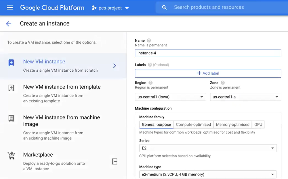
FIGURE 167 GCP Create Instance
On the Create Instance page:
Enter a Name for the new instance.
Select a Region and Zone.
Under Machine configuration:
For Series, select N1.
For Machine Type, select a minimum of n1-standard-2.
For Boot Disk, confirm that the correct image is already selected.
For Firewall, select the required HTTP/HTTPS options.
Expand the Management, security, disks, networking, sole tenancy options.
Select the Management tab.
Under Metadata:
For Key, enter pulse-config.
For Value, paste the text of the metadata file you downloaded earlier.
Select the Networking tab.
Under Network interfaces, click the Edit icon to change the default network interface selection.
The Network interface options appear.
Under Network interface, specify a private (internal) network interface:
For Network, select the required private VPC.
For Subnetwork, select the required subnetwork.
Click Done to confirm the settings for the private network interface.
Under Network interfaces, click Add network interface.
The Network interface options appear.
Under Network interface, specify a public (external) network interface:
For Network, select the required public VPC.
For Subnetwork, select the required subnetwork.
Click Done to confirm the settings for the public network interface.
(Optional) Click Add network interface and specify a management network interface.
Click Create to confirm the settings and instantiate a VM instance of the image.
The VM Instances page appears. This page shows the new VM instance of the image. For example:
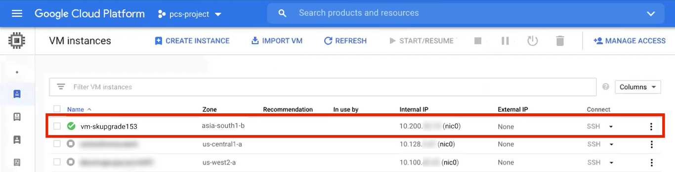
FIGURE 168 GCP Create Instance
On the VM Instances page, wait until the creation of the VM instance completes. This may take several minutes.
After the VM instance is created, click on it in the list of VM instances.
The VM instance details page appears for the instance.
Confirm the details for the VM instance, including the number of network interfaces.
Make a note of the public IP address of the EXT interface (typically, this is nic1. This is required inside nZTA.
Under Network interfaces, confirm that the firewall settings from your VPCs are present for your specified network interfaces:
Click nic0. A summary page for this network interface appears.
Under Firewall and route details, click the Firewall Rules tab and confirm that the following firewall rules are defined.
FIGURE 169 NIC0 Firewall Rules
Click nic1. A summary page for this network interface appears.
Under Firewall and route details, click the Firewall Rules tab and confirm that the following firewall rules are defined.
FIGURE 170 NIC1 Firewall Rules
(Optional) Click nic2. A summary page for this optional network interface appears.
Under Firewall and route details, click the Firewall Rules tab and confirm that the following firewall rules are defined.
FIGURE 171 NIC2 Firewall Rules
The VM instance details* page, click Connect to serial console
A console monitor view (in a separate browser tab) shows the ongoing boot-up process for the instance.
Wait until the instance boot up is complete, and shows a screen similar to the following:
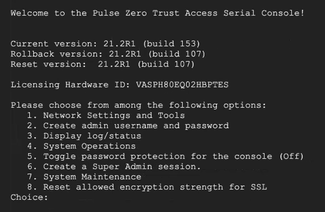
FIGURE 172 GCP Instance Console Monitor
You can then complete this process by updating the Gateway details on the Controller, see Completing the Configuration of the Controller.
Creating a VM Instance of the Uploaded GCP Image Using a Script/Template
This section describes how to automatically create a virtual machine instance of the ZTA Gateway image inside Google Cloud Platform using a script/template. You can also perform this process manually, see Creating a VM Instance of the Uploaded GCP Image Manually.
Ivanti provides YAML-based templates to create an instance of the ZTA Gateway image in the following configurations:
Two network interfaces in an existing VPC.
Three network interfaces in an existing VPC.
Download:
https://pulsezta.blob.core.windows.net/gateway/templates/GCP/23-2-883/ivanti-zta-2-nics-existing-vpc.zip
https://pulsezta.blob.core.windows.net/gateway/templates/GCP/23-2-883/ivanti-zta-3-nics-existing-vpc.zipTwo network interfaces in a new VPC.
Three network interfaces in a new VPC.
Download:
https://pulsezta.blob.core.windows.net/gateway/templates/GCP/23-2-883/ivanti-zta-2-nics-new-vpc.zip
https://pulsezta.blob.core.windows.net/gateway/templates/GCP/23-2-883/ivanti-zta-3-nics-new-vpc.zip
Note
You can obtain these templates through the links given here, or as part of the archive file set provided through the Download link on the Gateways Overview page in the nZTA Tenant Admin Portal after you have defined a Gateway record.
To use a template:
Download the required template archive file to your local workstation.
Unpack the downloaded archive file to a location that is accessible from Google Cloud Platform. Each archive contains three files. For example, for the two-interface (existing VPC) version of the archive:
pulsesecure-zta-2nics-existing-vpc.jinja
pulsesecure-zta-2nics-existing-vpc.jinja.scheme
pulsesecure-zta-2nics-existing-vpc.yaml
Edit the YAML file
propertiessection to reflect your project and instance requirements, including theuser_dataproperty.An example of an existing VPC YAML file is provided here:
imports:
  - path: pulsesecure-zta-2-nics-existing-vpc.jinja
resources:
  - name: my-vm
    properties:
      project: zta-gw-263035
      email: [email protected]
      region: asia-south1
      zone: asia-south1-b
      image: ztagcp123
      machine_type: n1-standard-2
      int_network:
      ext_network:
      int_subnetwork:
      ext_subnetwork:
      user_data:
    type: pulsesecure-zta-2-nics-existing-vpc.jinja
An example of a new VPC YAML file is provided here:
imports:
  - path: pulsesecure-zta-2-nics-new-vpc.jinja
resources:
  - name: my-vm
    properties:
      deploy_with_lb: yes
      project: zta-gw-263035
      email: [email protected]
      region: asia-south1
      zone: asia-south1-b
      image: ztagcp123
      machine_type: n1-standard-2
      user_data: <pulse-config><primary-dns>8.8.8.8<\primary-dns> ...
      int_cidr: 192.0.2.0/24
      ext_cidr: 192.0.2.0/24
    type: pulsesecure-zta-2-nics-new-vpc.jinja
Note
Where you are specifying a new VPC for your virtual machine instance, make sure you use properties (for example, networking settings) that do not conflict with an existing VPC.
The following table lists all possible template properties and their meaning:
Property
Description
Example Value
project
Project Identifier
myproject
email
Registered service account email address
email@example.com
region
The name of the region in which you want to deploy your VM instance
asia-east1
zone
The name of the zone in which you want to deploy your VM instance
asia-east1-b
image
Virtual machine image name
gwimage
machine_type
GCP machine type
n1-standard-4
int_network
VPC network name for internal network
nw1-private
ext_network
VPC network name for external network
nw1-public
mgmt_network
VPC network name for management network
nw1-mgmt
int_subnetwork
Subnet name for internal VPC
int-nw1
ext_subnetwork
Subnet name for external VPC
ext-nw1
mgmt_subnetwork
Subnet name for management VPC
mgmt-nw1
user_data
The Gateway config file downloaded from the nZTA controller
<pulse-config>… </pulse-config>
int_cidr
IP address range for the internal subnet
192.0.2.0/24
ext_cidr
IP address range for the external subnet
198.51.100.0/24
mgmt_cidr
IP address range for the management subnet
203.0.113.0/24
health_check
Health check rule name with port 443
hc1
ingress_pzt_int_port
Firewall rule for inbound internal network
ing-int
ingress_pzt_ext_port
Firewall rule for inbound external network
ing-ext
egress_pzt_ext_port
Firewall rule for outbound external network
egress
ingress_pzt_mgmt_port
Firewall rule for inbound management network
ing-mgmt
vm_name
Virtual machine instance Name
vm77
router_int
Cloud router name for the internal interface
rtr1
nat_int
NAT Gateway name for the internal interface
nat1
router_mgmt
Cloud router name for the management interface
rtr-mgmt1
nat_mgmt
NAT Gateway name for the management interface
nat-mgmt
ip_address
Load balancer front-end IP address
3nic
instance_group
Instance group name
group1
load_balancer
Load balancer name
lb
max_connections
The number of maximum connections
2
target_proxy
Targeted proxy name
proxy1
front_end
Load balancer front-end profile name
front1
Save the YAML file.
On the Google Cloud Platform, start a command line session from the title bar. For example:
FIGURE 173 GCP Upload Files
A command line session starts.
Select the required project:
gcloud config set project <project-name>
Within the project folder, create a deploymentmanager folder.
Copy the three script files to this folder.
Create a VM instance from the ZTA Gateway image archive file using the following command:
gcloud deployment-manager deployments create <vm-name> --config <yaml_file>
For example:
gcloud deployment-manager deployments create vm-gcp-123 --config pulsesecure-zta-3-nics-existing-vpc.yaml
Wait until the command completes.
On the VM Instances page, click on the new VM in the list of VM instances.
The VM instance details page appears for the instance.
Confirm the details for the VM instance, including the number of network interfaces.
Make a note of the public IP address of the INT interface (typically, this is nic0. This is required inside nZTA.
You can now complete this process by updating the Gateway details on the Controller, see Completing the Configuration of the Controller.
Completing the Configuration of the Controller
If you specified a dummy public IP address (for example, 1.1.1.1) when you created the Gateway on the Controller, you now need to update the Controller with the allocated public IP address for the Gateway VM instance on Google Cloud Platform.
Note
You do not need to perform the following procedure if you specified the correct public IP address when you created the Gateway on the Controller, see Adding a GCP Gateway in nSA.
Return to the Gateways List page in the nZTA Tenant Admin Portal.
Locate the new Gateway record in the list and confirm that its status has updated to Connected.
Click the Gateway and then select Secure Access > Gateways > Configuration.
Under Gateway Network Settings, delete the current public IP setting and replace it with the public IP address if the nic1 (external) interface for the VM instance.
(Optional) After you have registered a Gateway, you can configure it (or the Gateway Group to which it belongs) as the default Gateway if required. A default Gateway handles all requests from applications that are not referenced by any secure access policy. See Configuring a Default Gateway for Application Discovery.
Upgrading Gateways
Ivanti periodically creates and releases new Gateway software versions to address updates and issues, and to improve performance. As new version packages become available, you can trigger an upgrade for your Gateways through the Controller to take advantage of the updates available in the new version. Gateway updates can be applied manually, or, in the case of ungrouped Gateways, applied at a scheduled time.
The Installation Packages page displays a list of the available Gateway installation packages and controls the update schedule. To trigger a manual upgrade for a specific Gateway or Gateway Group, use the Gateways Overview page (see Checking a Current Gateway Version and Applying an Individual Update).
Note
The upgrade process requires a Gateway instance to become unavailable for a short time while the upgrade package is applied. Ivanti recommends performing Gateway upgrades ONLY at a time of least impact to your services.
Gateways that are part of a group (for high availability) can be safely upgraded provided the remaining group members remain connected and available.
To view the list of available Gateway installation packages and to configure a update schedule:
Log into the Controller as a Tenant Admin, see Logging in as a Tenant Administrator.
From the nZTA menu, click the Administration icon, then select Upgrade > Installation Packages.
The Installation Packages page appears.
Click the Gateways tab.
The list of available Gateway installation packages is displayed:
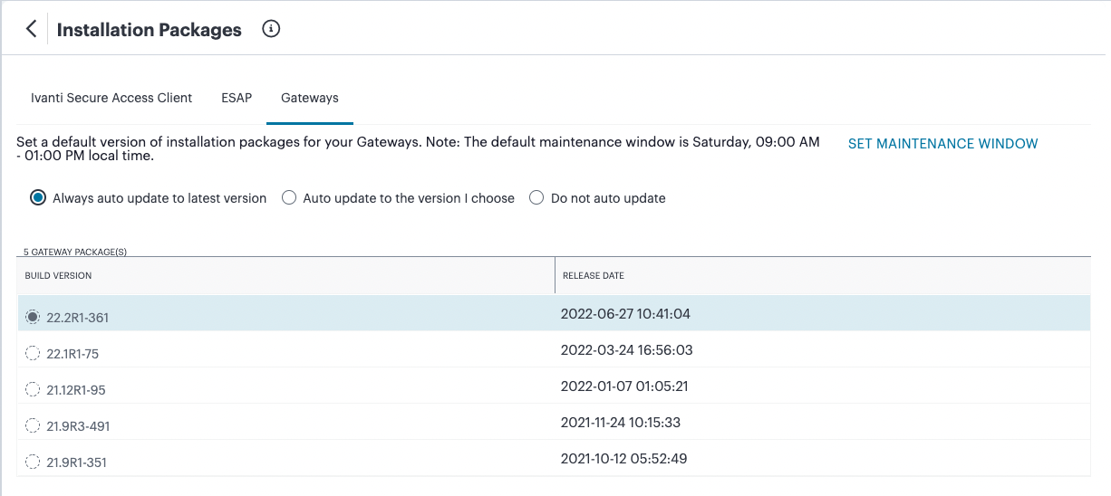
FIGURE 174 View a list of available Gateway installation packages and set a schedule for upgrades
Use the following controls to set the Gateway upgrade policy:
Always auto update to the latest version: Update your Gateways to the latest available version according to the defined maintenance window.
I will choose the version: Select a specific package from the list of available packages to be applied to your Gateways according to the defined maintenance window.
Do not set a default version: Do not automatically schedule an update, and leave your Gateways running the current version.
To set the default maintenance window for Gateway updates, click SET MAINTENANCE WINDOW.
The Maintenance Window dialog appears:
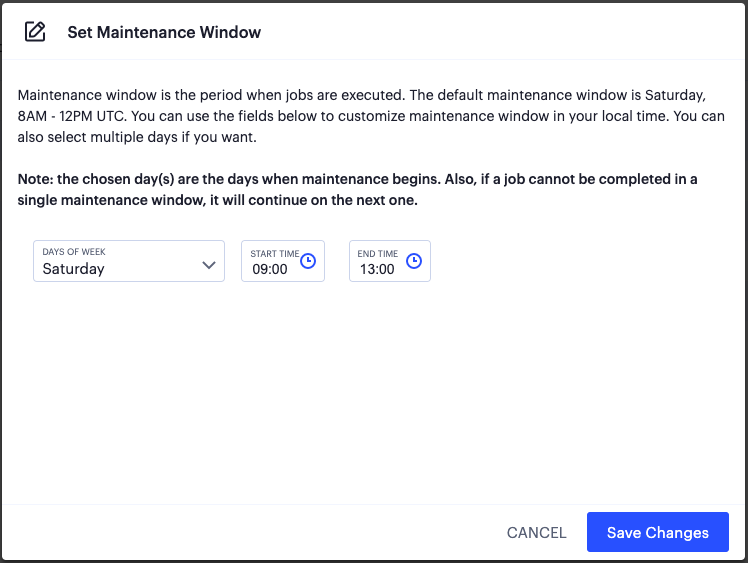
FIGURE 175 Set the default maintenance window for Gateways
Use the settings provided to configure your maintenance window, during which your non-grouped Gateways are updated to the selected package version. Ivanti recommends setting this at a time of least convenience to your services.
Note
If a scheduled update does not complete within the maintenance window, it continues at the next available maintenance window. However, if a scheduled update fails, try updating the Gateway manually (for more information, see Checking a Current Gateway Version and Applying an Individual Update).
Checking a Current Gateway Version and Applying an Individual Update
To check the current version for a Gateway, and to apply an update:
Log into the Controller as a Tenant Admin, see Logging in as a Tenant Administrator.
From the nZTA menu, click the Secure Access icon, then select Gateways > Gateway List.
The Gateways List page appears, showing the full list of Gateway Groups and standalone Gateways currently configured on the Controller.
Select the required Gateway from the list.
The Gateways Overview page appears. The summary at the top of the page displays details pertaining to this Gateway, including the current version:
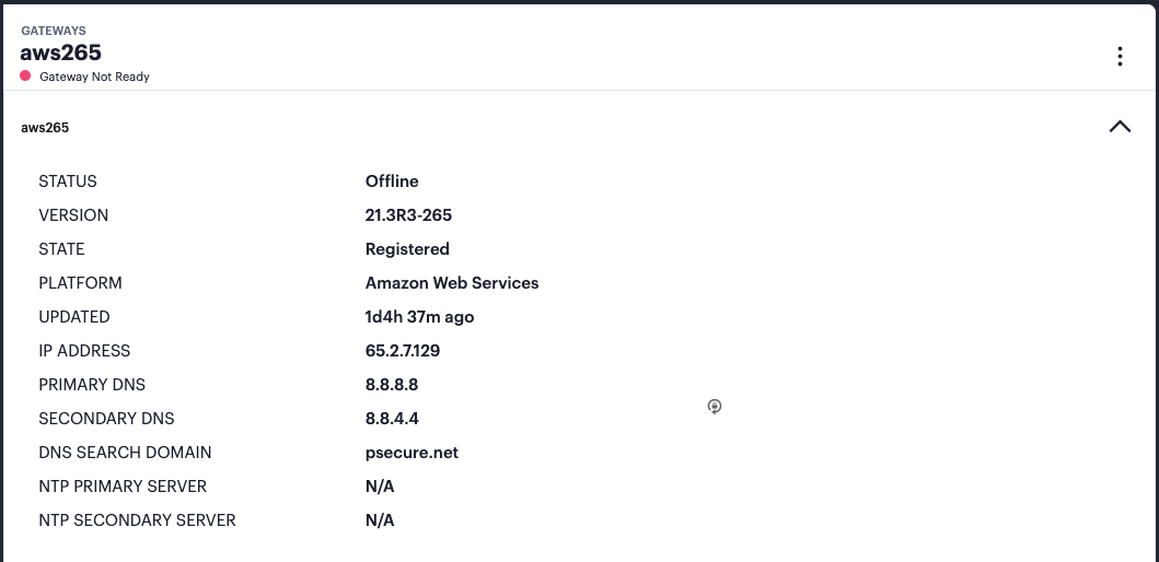
FIGURE 176 Viewing the current Gateway version
Click the context menu icon at the top-right to access the Edit options applicable to the selected Gateway:
If an update is available for this Gateway, a corresponding link is displayed in the drop-down menu:
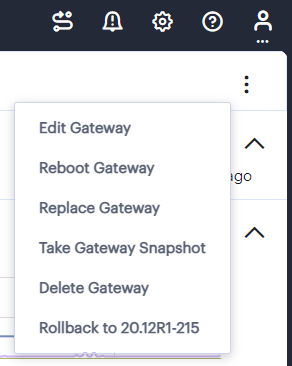
FIGURE 177 Viewing Gateway version upgrade options
Note
In some cases, there might be more than one version available. Select the version you want, or contact your support representative for details.
To start the upgrade, click the Upgrade to <version> link.
An upgrade task is added in the Tasks page for this Gateway, with a status of “Pending”. As the task becomes due, the upgrade process starts and the task status changes to “In Progress”. The status description describes the current phase of the upgrade, Downloading, Installing, or Rebooting, together with the percentage complete.
During the first two phases, your Gateway remains operating on the current version and continues to serve traffic. Then, in the reboot phase, the Gateway becomes unavailable for a short time.
After the reboot is complete, the Gateway automatically re-establishes connection to the Controller. If the procedure is successful, the upgrade task is marked with a status of “Success” and the new software version is displayed in the Gateway summary in the Gateways Overview page.
The time taken for an upgrade to complete is based on factors such as the number of previous pending tasks and network connection speed. Check on progress using the status description or through the host platform management console.
Note
The Controller UI displays the upgrade phase progress indicator (downloading, installing or rebooting) only for Gateway upgrades from base version 21.2 upwards. For base Gateway versions earlier than 21.2, an indication of the current progress is available only from the host platform management console.
To troubleshoot issues related to upgrading your Gateway, view the Event Log (see Checking the Logs). Furthermore, if a Gateway fails to initiate a reboot at the end of the upgrade process, but is still accessible, check the log file on the Gateway instance using the following steps:
Use
sshto access the Gateway instance command line.Locate and open the file
/tmp/doUpgrade.log.
Rolling Back a Gateway to a Previous Version
Your ZTA Gateways can be rolled back to a previously-installed version through the Tenant Admin Portal. You might want to return to an earlier version if, for example, you encounter an unforeseen issue with a newly-upgrading Gateway instance, or for testing purposes.
You can roll back a Gateway version only where that Gateway instance has been previously upgraded through the Tenant Admin Portal, and only to the previously-installed version.
To roll back a Gateway to an earlier version:
Log into the Controller as a Tenant Admin, see Logging in as a Tenant Administrator.
From the nZTA menu, click the Secure Access icon, then select Gateways > Gateway List.
The All Gateways page appears, showing the full list of Gateway Groups and standalone Gateways currently configured on the Controller.
Select the required Gateway from the list.
The Gateways Overview page appears. The summary at the top of the page displays details pertaining to this Gateway, including the current version.
Click the context menu icon at the top-right to access the Edit options applicable to the selected Gateway:
If a rollback function is available for this Gateway, a corresponding link is displayed in the drop-down menu:
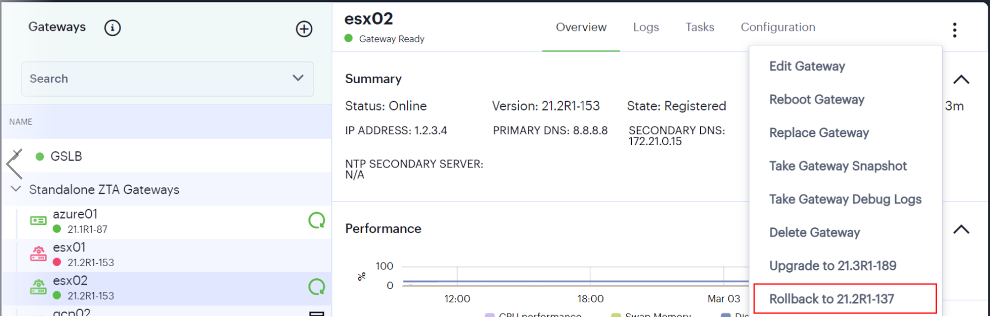
FIGURE 178 Viewing the Gateway version rollback option
Select the rollback link.
A rollback task is added in the Tasks page for this Gateway, with a status of “Pending”. As the task becomes due, the rollback process starts and the task status changes to “In Progress”.
As the process starts, your Gateway remains operating on the current version and continues to serve traffic. Then, after the earlier version is reinstated, the Gateway reboots and becomes unavailable for a short time.
After the reboot is complete, the Gateway automatically re-establishes connection to the Controller. If the procedure is successful, the upgrade task is marked with a status of “Success” and the new software version is displayed in the Gateway summary in the Gateways Overview page.
Configuring a Default Gateway for Application Discovery
nZTA directs requests from each application towards the Gateway defined in the secure access policy for the application.
For requests for applications not referenced by a secure access policy, you can define a default Gateway on the Controller. This enables packet analysis to be conducted on requests passing through the Gateway to assess the validity of the requests.
To view usage metrics for application and resource requests handled by the default Gateway, see Reviewing Application Usage.
Two default Gateway scenarios are supported:
Any single Gateway at v21.1 (or later) can be assigned to act as the default Gateway. This Gateway is used exclusively as the default Gateway.
Alternatively, any Gateway Group whose Gateways are all at v21.1 (or later) can be assigned to act as the default Gateway. In this scenario, all Gateways in the group are used exclusively as the default Gateway. The Gateway Group is typically fronted by a load balancer to enable the required distribution of requests across the Gateways in the group.
To configure a default ZTA Gateway, you must edit and update the built-in Application discovery secure access policy to reference a single Gateway or Gateway Group.
The default Gateway (or Gateway Group) then handles all requests from applications on enrolled devices that are not referenced by any other secure access policy.
Note
Ivanti Secure Access Client version 21.1 is required to work with application discovery and a default Gateway.
Note
Ivanti Secure Access Client Linux variants do not currently support the use of a default gateway.
To assign a Gateway (or Gateway Group) as the default Gateway:
Log into the Controller as a Tenant Admin, see Logging in as a Tenant Administrator.
From the nZTA menu, click the Secure Access icon, then select Secure Access Policies.
The Secure Access Policies page appears. This lists all current secure access policies.
Locate the Application discovery secure access policy and examine its Enabled property:
If the policy is enabled, select the check box for the policy and then click Disable.
Select the check box for the Application discovery secure access policy and click Edit.
The Edit Secure Access Policy dialog appears.
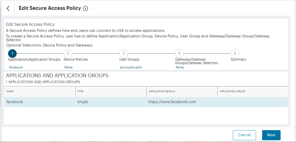
FIGURE 179 Editing a Secure Access Policy
Note
The Application Type and Application cannot be changed.
Click Device Policy and select the required device policy.
Click User Group for the required user group. All users identified in this group will be able to access the default Gateway.
(Optional) For a default Gateway that is a single Gateway:
Ensure Gateway Type is set to Single.
Click Select a Gateway and select the required default Gateway.
Note
This Gateway must be at (v21.1 or later), and cannot already be referenced by another secure access policy.
Click Save. The Secure Access Policies page updates to reflect the selection.
(Optional) For a default Gateway that is a Gateway Group:
Ensure Gateway Type is set to Group.
Click Select a Gateway Group and select the required default Gateway Group.
Note
All Gateways in this Gateway Group must be at (v21.1 or later), and cannot already be referenced by any other secure access policies.
Click Save. The Secure Access Policies page updates to reflect the selection.
Select the check box for the Application discovery secure access policy and click Enable.
The Secure Access Policies page updates to reflect the selection. The policy is pushed to the selected Gateway or Gateway Group.
The default gateway configuration is complete, and the default Gateway can be used by any enrolled macOS/Windows desktop device to support application discovery after it accepts the new policy.
To enroll and use Ivanti Secure Access Client on a device, see Enrolling Mobile/Desktop Clients.